Week 9 - Project 1 - Door Applique Design with Engineering Features
AIM:
- Create the Base Bracket Plastic component through the given Class-A surface. To begin with, the tooling axis for the given Class-A Surface should be created meeting the requirements of the draft angle and at the end perform the Draft analysis on the model.
- Create the Heat Stakes and the locators considering the design rules mentioned in the video for the door applique.
OBJECTIVE:
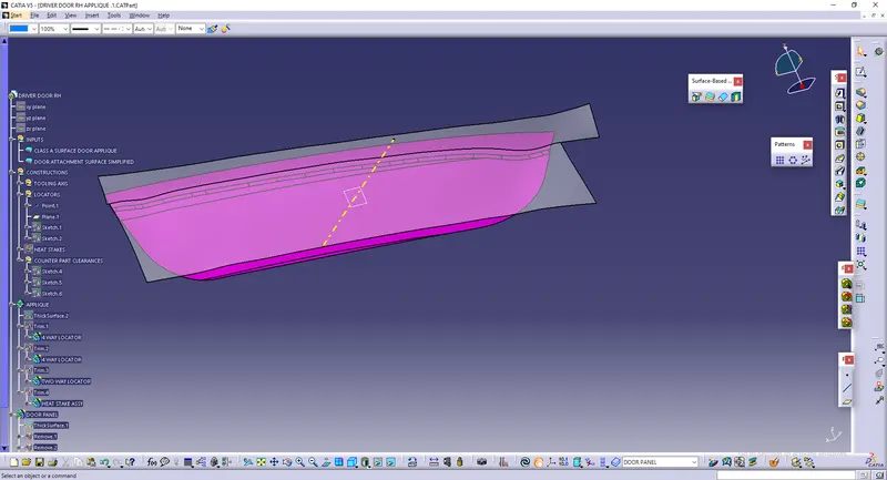
Design of an Automotive Plastic Component – Driver Side RH Door Applique Design with 4-Way, 2-Way Locators and Heat Stakes using industry principles and Design Rules. Concepts such as Rib design rules, Draft angles, Draft Analysis, Determining the Tooling Axis, Class A, Class B and Class C surfaces. The component is designed to maintain a wall thickness of 2.5mm for Applique using Surface Design and Solid Design techniques in CAD package CATIA V5.
INTRODUCTION
Heat Staking:
- Heat staking also known as thermoplastic staking is the process of joining two dissimilar materials together.
- In heat staking we use local heating and cooling to raise the temperature of plastic components and allow plastic reforming to be carried out.
- This reforming can be used in a wide variety of applications.
- The Plastic Stud protrudes through a hole in the component to be locked in place.
- Heated thermal tips are used to melt the top of the studs which fills up the volume of the cavity to produce a head locking the component in place.
- The progressive melting of plastic under continuous pressure forms the head.
- When staking, the right combination of heat and pressure is critical.
- Applications range from staking plastic boss’s for assembly of car door panels to joining PCB’s to plastic housings.
- Benefits of this technique include; no vibration damage, no particulates, the ability to stake metalized coated applications and the capability to stake in difficult to access or restricted areas.
- In short the Locators locate the component and lock 12 degrees of freedom whereas the Heat Stake is a Fixation which locks the Final DOF.
Advantages of Heat Stakes:
- Similar and dissimilar materials may be joined: metal to metal, plastic to plastic, metal to plastic.
- Accurate control operating within a small process window.
- Local heating resulted in no damage to surrounding materials.
- Processing of glass-filled materials.
- No mechanical vibration.
- Many heat-stake shapes are possible through custom designed tools.
2 and 4 way locators:
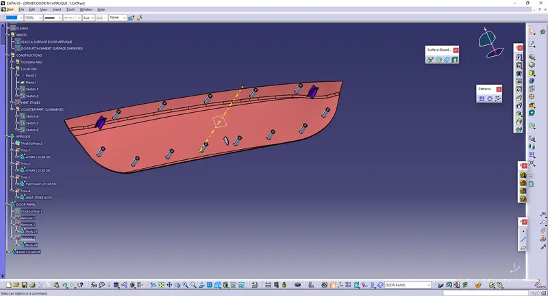
- Locators are used to locate a job or a component to arrest its degrees of freedom using the 3-2-1 Principle which is arresting 3 DOF first, then 2 DOF's and last DOF in a sequence.
- A 4 way locator will look like a '+' and a 2 way locator will look like a '-' .
- Both these locators use the same Rib Design Rules and principles.
- These Locators are placed on the B side of the component and must have the same height with respect to the B surface.
Rib:
- Rib is a B-Side Engineering feature which provides a means to economical Stiffness and Strength in Plastic Molded parts without increase in overall wall thickness.
- Rib also facilitates locating and arresting components of an assembly.
- It provides alignment in Mating Parts.
- It acts as Stop and Guides for Mechanisms.
Guidelines For Rib Design:
|
Rib Specification |
No-Show Surfaces |
Show Surfaces |
|
Draft Angle |
Min 0.5º per side, Recommended 1.5º per side |
0.5º per side |
|
Rib Thickness at Base (w) |
0.5 * t |
0.4 * t |
|
Rib Thickness at top |
Min 0.75mm |
Min 0.75mm |
|
Rib Height (y) |
Max 5*t |
Max 5*t |
|
Spacing Between 2 Ribs (x) |
2*t |
2*t |
|
Fillet Radius (r) |
0.125*t |
Max 0.25mm |
|
Rib Root Dia |
± 30 % of t |
± 30 % of t |
|
y/x ratio for multiple ribs |
3:1 2:1 preferred |
3:1 2:1 preferred |
DESIGN RULES OF PLASTIC COMPONENTS
- Nominal wall thickness of a plastic component is 3mm. For a strength component such as Instrument Panel, Bumper , door trims the values of thickness are larger than 4mm. For example, Thickness of IP may lie between 5-6mm, for Bumper it may be 6-8mm. For smaller components the thickness may be between 2-3mm as in this case of Coin Holder.
- Deviation of `30% from the wall thickness is allowed with gradual increase or decrease to avoid any plastic defects while manufacturing. For example: A component having wall thickness 3mm should deviate within the range of 2.1 mm minimum and 3.9 mm maximum.
- Ideal draft angle should be 3º for the overall component along for the faces lying in the tooling direction.
Fixture Design Rules:
- For a fixture designer, the major portion of design time is spent deciding how to locate the workpiece in the fixture.
You know that any free body has a total of twelve degrees of freedom as below:
6 translational degrees of freedom**: +X, -X, +Y, -Y, +Z, -Z**
And 6 rotational degrees of freedom:
- Clockwise around X-axis (CROT-X)
- Anticlockwise around X-axis (ACROT-X)
- Clockwise around Y axis (CROT-Y)
- Anticlockwise around Y axis (ACROT-Y)
- Clockwise around Z-axis (CROT-Z)
- Anticlockwise around Z-axis (ACROT-Z)
You must fix all the 12 degrees of freedom except the three translational degrees of freedom (-X, -Y, and -Z) in order to locate the workpiece in the fixture. So, 9 degrees of freedom of the workpiece need to be fixed By using the 3-2-1 method as shown below: - Rest the workpiece on three non-collinear points of the bottom surface (XY), and you will be able to fix the +Z, CROT-X, ACROT-X, CROT-Y and ACROT-Y degrees of freedom**.**
Now, rest the workpiece at two points of the side surface (XZ), and you will be able to fix the +Y and ACROT-Z degrees of freedom.
Now, rest the workpiece at one point of the adjacent surface (YZ), and you will be able to fix the +X and CROT-Z degrees of freedom.
So, you can successfully fixate 9 required degrees of freedom by using the 3-2-1 principle of fixture design. - The jig and fixture are tools used for holding the workpiece in a correct location for mass production. Various types of fixtures are used in the industry. The 3-2-1 method is the fundamental principle for all types of fixture design.
PROCEDURE
Steps to be followed:
Step-1
Class A Input
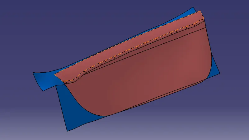
First input the given Class A into the CATIA software.
Design Check on received Class A:
- After receiving the Class-A for the Applique check for the connectivity of the surfaces on it.
- Use Join operation, boundary operation and disassemble.
- The check is over if any discontinuities do not arise.
Step-2
Determine the Tooling Axis:
- Identify faces which can potentially create problems while manufacturing.
- Surfaces at angles along a desired Tooling Axis.
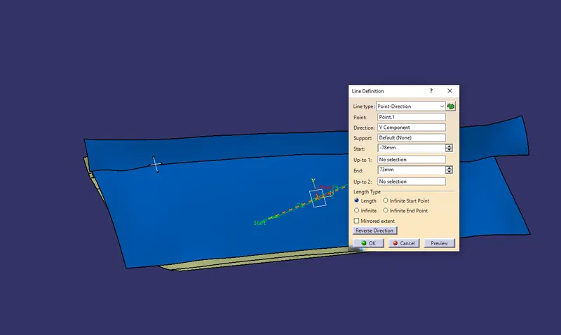
- Extract a plain surface and create a point on its center for Tooling Axis creation.
- In this case Y axis can be a possible Tooling Axis Direction.
- Also there are no negatively angled problematic walls, so the tooling axis is created along Y axis as shown in Figure5.
Step-3
Perform Draft Analysis on Class A Surface:
- Change View Mode Customization to Material mode
- Go to INSERT ---> ANALYSIS ----> FEATURE DRAFT ANALYSIS and move the compass to the Tooling Axis.
- Change the range to 2.9º.
- Apply the settings as Shown in Figure
Class B Surface Creation:
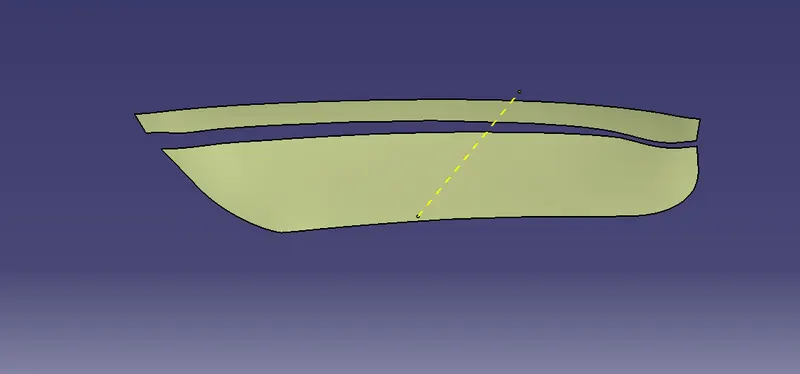
- Extract the relevant surfaces from Class-A surface which excludes the Fillets.
- Here the selected faces consist of 2 walls.
- Extract of these surfaces is shown in Figure .
Step-4
Class C Surface Creation:
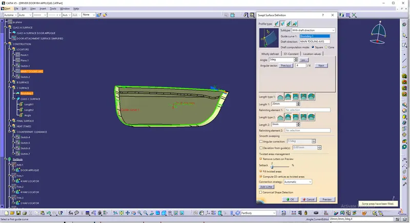
- Extract the edges of the A surface separately as shown in Figure 13
- Use Sweep Operation to extrude the boundary using the ‘With Draft Direction’ option and selecting the boundary for Guide curve and the Tooling Axis as Draft Direction.
- Use angle as 3º draft and select outward direction with appropriate length say 20mm as shown in Figure.
Step-5
Final Closed Surface Creation:
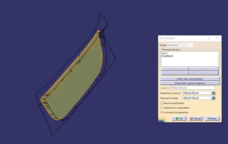
- Join all the Class C surfaces along with the Class A Surface and trim it with Class B Surface.
- The Final trim should be one single Surface Entity without any gaps as shown in Figure.
Step-6
Create a Closed Body Part from Final Closed Surface:
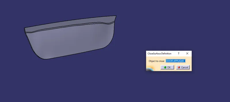
- Switch to Part Design Workbench and use Closed Surface option to create a Solid Part from the final obtained surfaces.
- The part created is the required Applique designed from a Class A.
- The obtained solid Part is shown in Figure.
Step-7
Create Locators and Heat Stakes on B Surface
- Create a Plane on the B side.
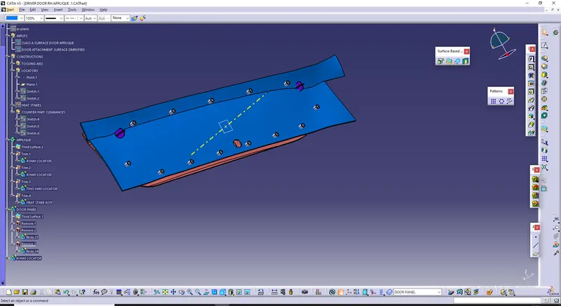
- Create a sketch for a 4 way locator as shown in Figure.
- Create a sketch for a 2 way locator on the same plane as shown in the bottom location in the above figure.
- Extrude the Locators maintaining a thickness of 1.25mm as per rib design rules.
- Translate the 4 way locator to the right side so that all the locators are placed equally far away.
- Make sure the height of the locator is maintained within the rib design rules.
- Create a sketch of concentric circles for the Heat Stakes .
- Maintain Wall thickness as per Rib design rules and extrude the heat stakes at a level which is below the locators by at least 5mm.
- Ensure that each heat stake is at least 50mm apart from each other
- Give Drafts of 0.5 degrees to the walls of all the locators and the heat stakes
- Use Union Trim to keep the required faces with respect to the Applique Body.
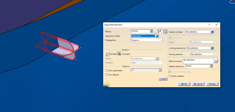
- Give Fillets to all the walls and make entry chamfers for the Locators.
Step-8
Draft Analysis on Final Body:
Draft:
- Draft is an angular tapering given at the design stage to every Plastic Component that has to be manufactured.
- It is given in the direction of the Mold Movement.
- The Draft allows the parts to release easily from the mold without creating friction between the surface of the component and the core and cavity plates.
- When a Plastic component cools down inside the mold, the natural tendency of it is to shrink and attach to the core or cavity half.
- The movement of mold opening causes friction on the walls of the component as well as the core/cavity blocks.
- This reduces the life of the mold as well as the component itself.
- The component may also have rough surface finish as well as weak structure due to this.
- This problem can be solved by giving draft to the component.
- Most applications require minimum draft angles of around 0.5º to 1º , however 3º draft angles are widely accepted for cost saving purpose.
- 7º Draft angles are given to textured surfaces like Instrument Panels.
- Minimum possible draft angles are given to screw bosses, ribs and stiffeners due to their critical nature.
- Walls having 0º or negative draft are difficult to manufacture thus, are required to redesign from the Class A stage.
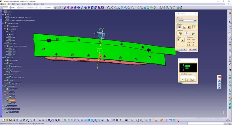
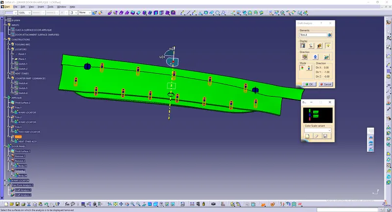
Analysis :
- Change View Mode Customization to Material mode
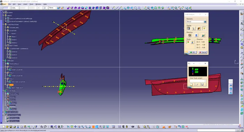
- Go to INSERT ---> ANALYSIS ----> FEATURE DRAFT ANALYSIS and move the compass to the Tooling Axis.
- Change the range to 0.48º.
- Apply the settings as Shown in Figure 37.
- The Final Draft analysis passes on the whole component of Applique along the Main Tooling Axis hence it can be manufactured.
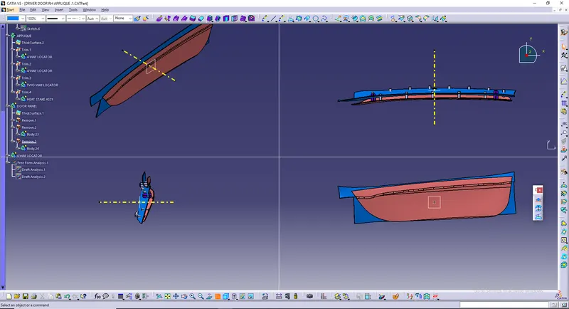
VIEWS (ISOMETRIC, SIDE, TOP, FRONT)
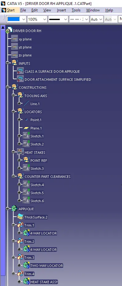
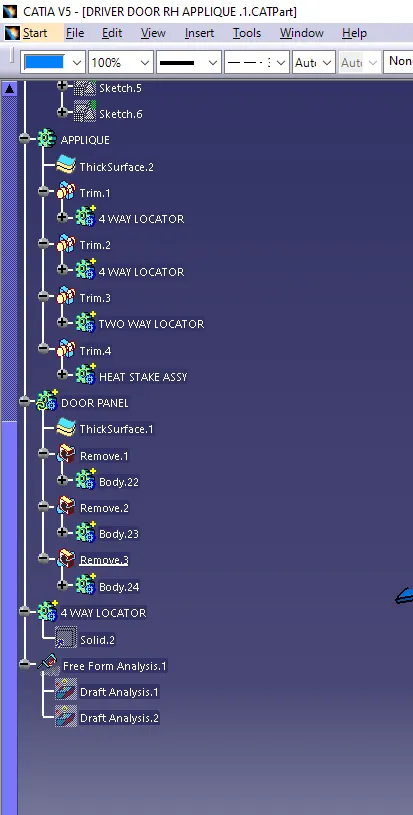
Tree Structure:
CONCLUSION:
The Design of Automotive Plastic Component –Driver Side RH Door Applique Design with 4-Way, 2-Way Locators and Heat Stakes has been completed by using industry principles such as Rib design Rules, Draft Angles, Draft Analysis for Class A and Final enclosed surface, Tooling Axis creation and implementation, Class B and Class C creation and conversion to a solid part.