Week -2
STUDY-1
AIM:
- To simulate a simulink model of a doorbell using solenoid block and observe the output.
OBJECTIVE:
- To create a situation where the switch is closed for 2 seconds and then released. To observe the physical movement of the plunger.
THEORY:
DoorBell
A simple construction of a doorbell is as shown in the figure.1 below.
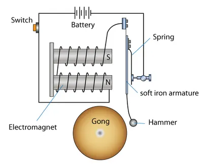
When the switch is pressed the circuit is completed and the electromagnet is activated which makes the hammer strike the ball. A solenoid is created by winding copper wire over a cylindrical casing. When electricity is passed through the coil the solenoid acts like a magnet. In this project, we have used a solenoid valve to demonstrate the working of the doorbell.
Solenoid
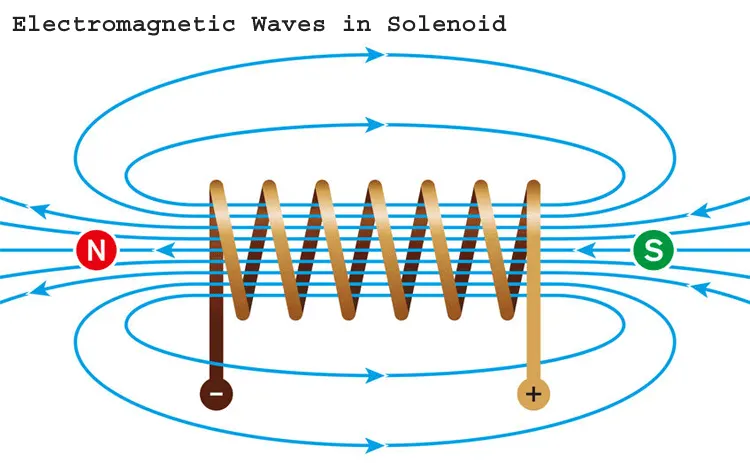
A solenoid is a device consisting of a coil of wire, the housing and a moveable plunger (armature). When an electrical current is introduced, a magnetic field forms around the coil which draws the plunger in. More simply, a solenoid converts electrical energy into mechanical work.
MODEL:
WORKING:
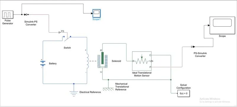
- The signal source is connected with the switch.
- A battery is connected with the solenoid.
- Solver block is used to simplify the physical conditions at the switch.
- Electrical reference is given for battery.
- Solenoid plunger is connected with an ideal motion sensor which is connected with a scope block.
- P-s converters and vice-versa is used whenever needed.
INPUT:

OUTPUT:
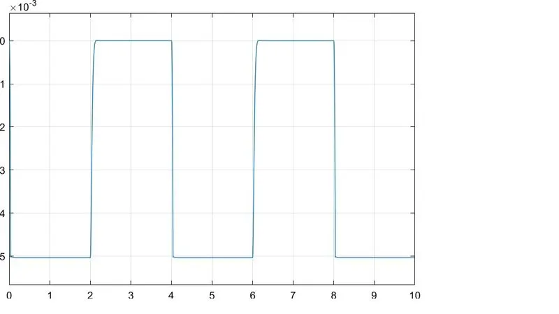
The output follows the input signal except for the fluctuations related to the mass of plunger and spring stiffness and damping the open fluctuations can be damped it the solenoid rating voltage is the same as the battery output.
STUDY-2
AIM:
To model a control system using a thermostat for a DC-motor fan.
Conditions:- Temperature source must be kept at 0 to 20 degree celsius for 10sec. 27 degree celsius for next 20 sec and 23 degree celsius for next 20 sec. The total cycle is 50 sec.
Thermistor
A thermistor is a resistance thermometer, or a resistor whose resistance is dependent on temperature. The term is a combination of “thermal” and “resistor”. It is made of metallic oxides, pressed into a bead, disk, or cylindrical shape and then encapsulated with an impermeable material such as epoxy or glass.
There are two types of thermistors: Negative Temperature Coefficient (NTC) and Positive Temperature Coefficient (PTC). With an NTC thermistor, when the temperature increases, resistance decreases. Conversely, when temperature decreases, resistance increases. This type of thermistor is used the most.A PTC thermistor works a little differently. When temperature increases, the resistance increases, and when temperature decreases, resistance decreases. This type of thermistor is generally used as a fuse.
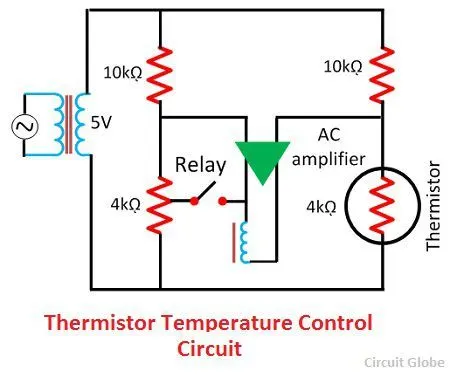
Typically, a thermistor achieves high precision within a limited temperature range of about 50ºC around the target temperature. This range is dependent on the base resistance.
MODEL:
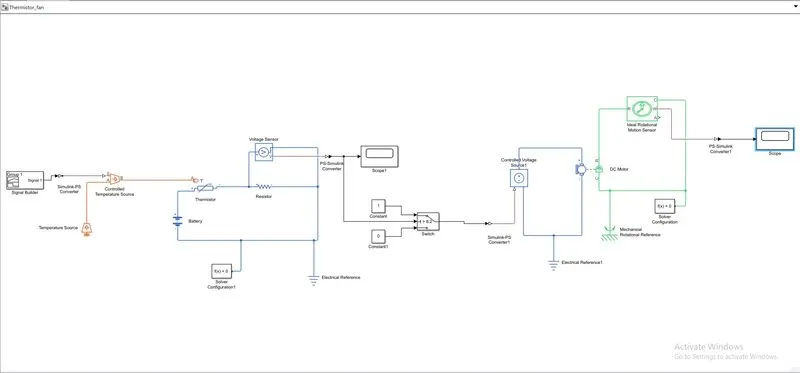
EXPLANATION:
- The sensor is connected with a variable heat source.
- A battery source is provided to the thermostat circuit for measuring the change in voltage.
- The output of the voltage sensor is connected with a switch as a reference.
- The switch is connected with the current source for DC-motor.
- The output for the Dc-motor is connected with the ideal rotation motion sensor. Which is connected with a scope block.
- In order to sense the voltage, a voltage ensor was used its positive and negative terminal were connected to the respective terminals of the resistance, and a is output voltage signal was connected to the solver configuration block and then converted to simulink signal and then shown on a display.
INPUT RESULT:
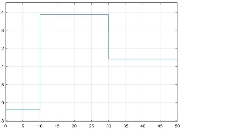
- Signal builder is connected instead of the constant where a signal of time value [0 10 10 30 30 50] and a temperature values of [293,293,300,300,296,296] were used to generate a signal.
- The simulink PS converter was configured differently to take the first derivatives in order to provide enough inputs and to provide the derivatives required.
- The simulation time was changed to 50 seconds to capture all the events.
OUTPUT RESULT:
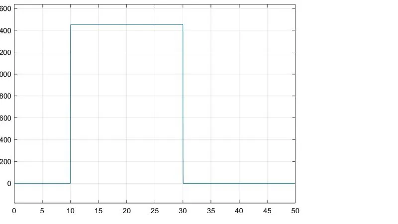
An output scope plot shown below depicts that when the temperature reached above 25 degree celsius, the DC motor representing the fan was off for initial 10 seconds and then started working at 10th second showing the result of the motor and then, the motor turned off after 20 seconds at 30th second for the remaining 20 seconds of the time till 50th second.
CONCLUSION:
It can be cocludd that both the studies were a success where outputs observed were:
- When a doorbell rang, a deflection was observed in the scope plot.
- When the DC motor turned on and off when there was temperature difference was noticed by the thermistor an the switch and the RPM of the motor wasobserved in the scope plot in the end.