Week 9 - Parametric study on Gate valve.
AIM:- To perform a parametric study on the gate valve simulation by setting the opening from 10 % to 80%.
OBJECTIVE:-
- Obtain the mass flow rates at the outlet for each design point.
- Calculate the flow coefficient and flow factor for each opening and plot the graph.
- Discuss the results of the mass flow rate and flow coefficient.
INTRODUCTION:-
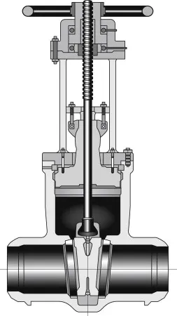
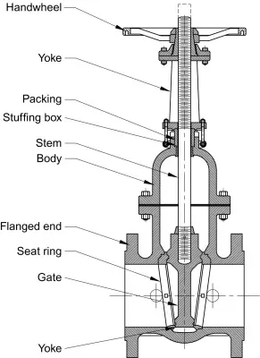
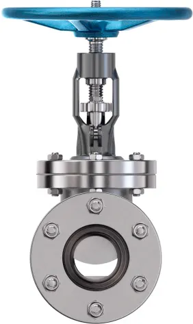
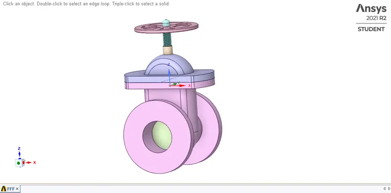
A gate valve is generally used to completely shut off fluid flow or, in the fully open position, provide full flow in a pipeline. Thus it is used either in the fully closed or fully open positions. A gate valve consists of a valve body, seat and disc, a spindle, gland, and a wheel for operating the valve. The seat and the gate together perform the function of shutting off the flow of fluid. A typical gate valve is shown in Fig. below,
Gate valves are generally not suitable for regulating flow or pressure or operating in a partially open condition. For this service, a plug valve or a control valve should be used. It must be noted that because of the type of construction a gate valve requires many turns of the hand wheel to completely open or close the valve.
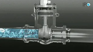
The valve is used to open or close the gate valve. When the wheel with handle is rotated then Gate or wedge moves upward or downward across the flow of any fluid. The mechanism on which the Gate valve works: When you rotate the handle wheel clockwise then steam and get moves in the downward direction across the fluid flow, and the gate is tightly located between two seats.
So that there is no leakage of any fluid when the valve is closed completely. When you rotate the handle Wheel in an anticlockwise direction, steam and fluid move upward at the same time across the fluid flow. The valve is opened Chrome closed position that permits the flow of fluid through the Gate valve.
Once Gate is completely opened, which permits very low resistance or no resistance to the flow of any field.
---------------------------------------------------------------------------------------------------------------------------------------------------------
Methodology:-
Geometry:-
- First, we have to Import the geometry in the Spaceclaim of the ANSYS Fluent. Geometry named as 'Gate Valve. stp'.
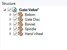
- We can see the Geometry in the figure below and also we can see the All Parts of the Gate Valve in the Following Structure Tree.
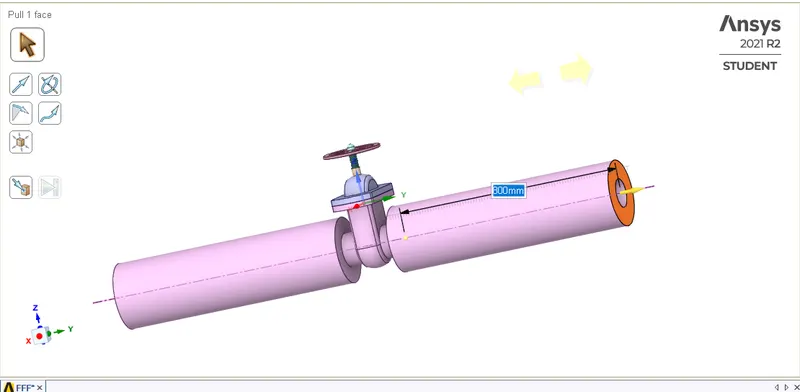
- After Importing the Geometry move the both face at inlet and outlet of the gate valve and extend the face's upto 800 mm on the both sides. To Simulate the proper flow while defining the inlet and Outlet in the Boundary conditions of the Gate Valve.
- After the Extension, the hide all the parts of the Gate valve to see the Gate Disc clearly.
- Then Click on the Move command and then click on the Gate disc and move it in upward direction by 7.5 mm Lift on the basis of 10% opening.
- TO analyze the Flow and its effects, we must allow the flow, and for that we have given the '7.5mm' lift to the Gate Disc.
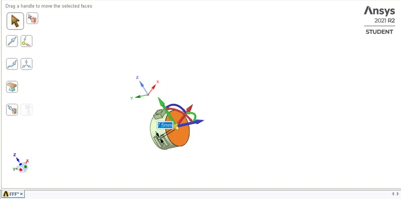
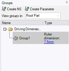
- After that If we are able to see the 'P' symbol to create Paramter then Click on the symbol and If we are not able to see the "P'' symbol Go to the Left Side and Click on the Create Parameter and then It shows that group has been created for the Lift.
- On the Left side, in the tree structure, if we see the Group options, we can see created Group and the amount of parameter, which has been set for 7.5mm Lift and we can change It directly also.
- Then extract the Fluid volume by selecting the Edges of inlet, Outlet and the upper Edges of the Bottom Part.
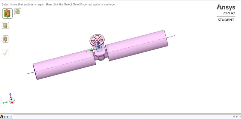
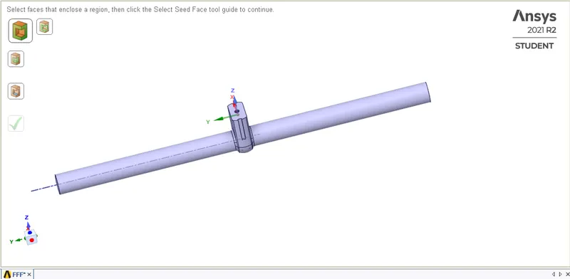
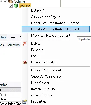
- After that To analyze the Fluid Flow upto the Paramteric value's or opening of the Gate Disc we go To the Volume and inside Volume after Right clicking we click on 'Update Volume Body in Context'.
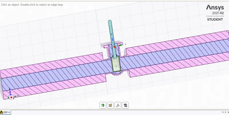
- Here, is the cross-sectional Figure of the Gate Valve after 'Update the volume body in context'. After that click on 'Supress For physics' for all the Parts and Hide them Expect Spindle, Bottom and Gate Disc must be Visible.
Meshing:-
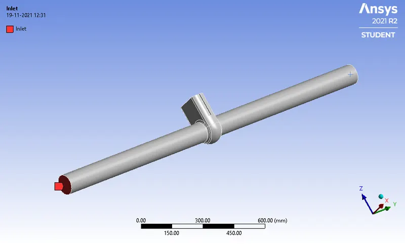
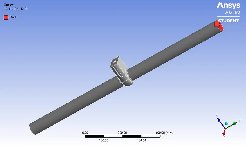
- First you have to select the Names of the Geometry as per the Boundary Conditions by the Named Selection Command.
Inlet
Outlet
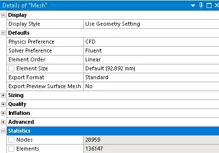
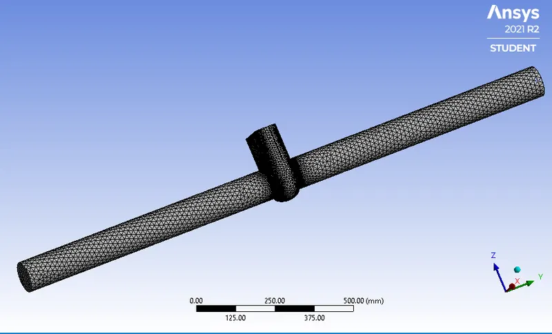
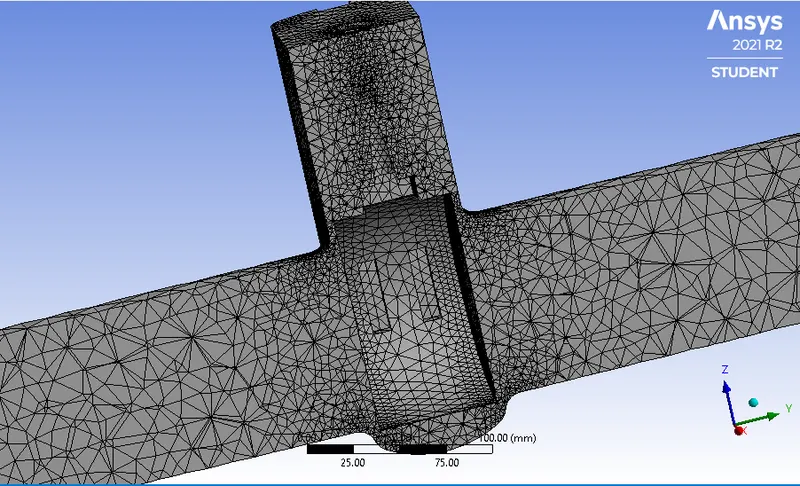
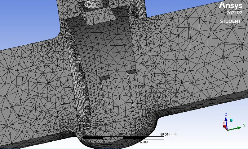
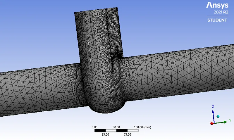
- Mesh Details:-
Mesh Figures:-
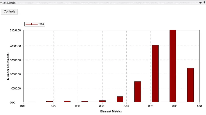
Mesh Quality:-
Setup:-
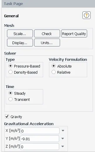
- General Setup:-
- Solver=> Pressure-based, Gravity on and give value of Gravity in negative y-direction.
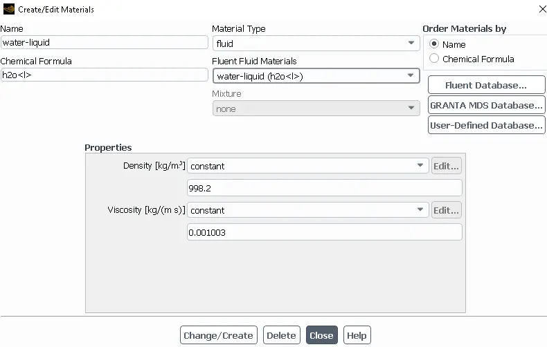
- Material Selection:-
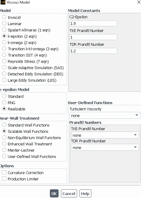
- Viscous Model=> K-epsilon, Realizable.
- Near- wall treatment => Scalable Wall Functions.
- Boundary conditions setup:-
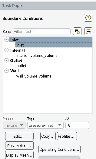
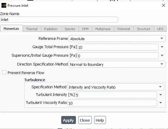
- Inlet: type=> Pressure-Inlet, Guage Total Pressure=> 10 Pascal.
- Outlet: type=> Pressure-Outlet, Guage Total Pressure=> 0 Pascal.
- Walls : Type=> Wall, Wall motion Stationary wall.
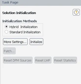
- Hybrid Initilazation
- Reports Setup:-
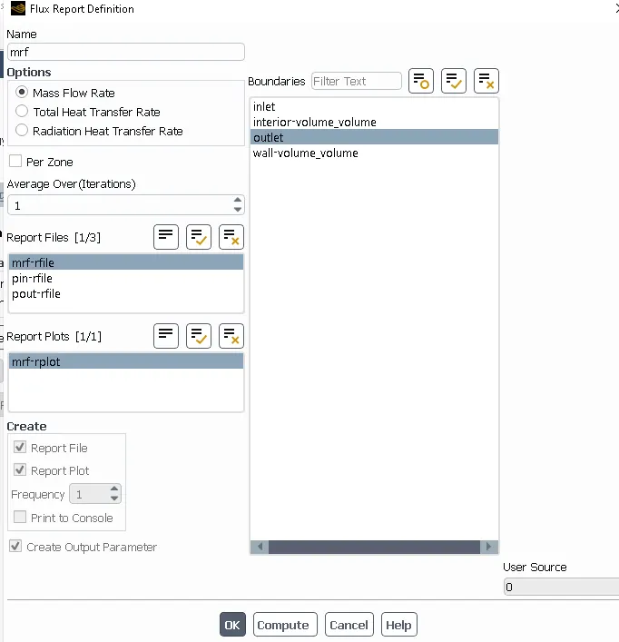
- Go to Definations> Flux Report> Mass Flow Rate and select at Outlet on where have to find the discharge.
- Go to Definations> Surface Report>Area-weighted Average> Find the Pressure Values at Inlet and Outlet set according to the case.
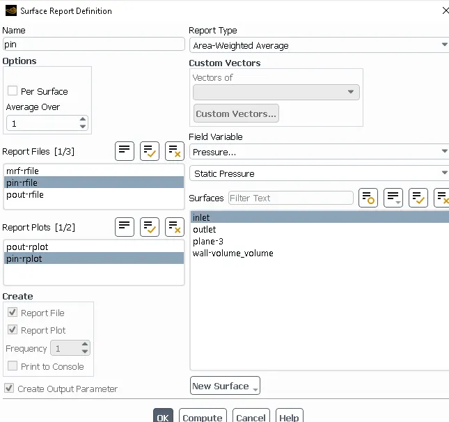
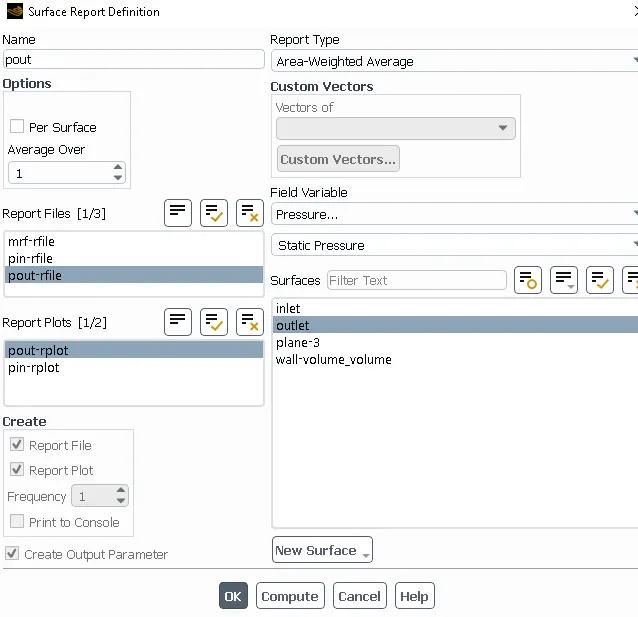
- After that Go to Run and Calculations. Give the no of Iterations For this case we simulate the upto 250 Iterations. and After 250 Itertaions Here, are the Results as shown below.
Parametric Study:-
- In the Following Image as shown below we can see the Paramteric Study at different Design 'Points' of the Lift of Gate valve.
- On the Completion of the simulation, select 'Paramter Set' and give the input values for the parametric Study at different design Points.
- Then click Indivisual cases and then Click on the Update Current Deisgn Point and Similarly, Select all the Points and Update them.
- Important Note:Retain column Must be checked for all the Cases.
Parametric data :-
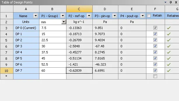
- We can see the Mass Fow Rate, Pressure at Inlet and Pressure at Outlet Results for all the Cases After the Update all Design Points.
- Now, We can Check all Design Points one by one and Go for the Detailed Results Like the Mass Flow Rate, Pressure Inlet and Pressure Outlet plots.
- In the CFP-POST we can get the Results or contours of Velocity and Pressure of all the cases one by one.
--------------------------------------------------------------------------------------------------------------------------------------------------
Now, we will see the the Results For all the Cases of Lift of 'Gate Disc' From 10% to 80% one by one.
- We will discuss each case Particularly, and Calculate the flow coefficient and flow factor for each opening.
- We will discuss the results of the mass flow rate and flow coefficient.
Flow Coefficient:-
The flow coefficient of a device is a relative measure of its efficiency at allowing fluid flow. It describes the relationship between the pressure drop across an orifice valve or other assembly and the corresponding flow rate.
Mathematically the flow coefficient Cv (or flow-capacity rating of valve) can be expressed as :
where:
- Q is the rate of flow (expressed in US gallons per minute),
- SG is the specific gravity of the fluid (for water = 1),
- ΔP is the pressure drop across the valve (expressed in psi).
In more practical terms, the flow coefficient Cv is the volume (in US gallons) of water at 60 °F that will flow per minute through a valve with a pressure drop of 1 psi across the valve.The use of the flow coefficient offers a standard method of comparing valve capacities and sizing valves for specific applications that is widely accepted by industry. The general definition of the flow coefficient can be expanded into equations modeling the flow of liquids, gases and steam using the discharge coefficient.
Flow Factor:-
The metric equivalent flow factor (Kv; commonly used everywhere else in the world with the exception of the United States) is calculated using metric units :

where
- Kv is the flow factor (expressed in
 ).
). - Q is the flowrate (expressed in cubic metres per hour [
 ]),
]), - SG is the specific gravity of the fluid (for water = 1),
- ∆P is the differential pressure across the device (expressed in [bar]).
Kv can be calculated from Cv using the equation:

RESULTS:-
For Case1: Dp0 10%
Residuals:-
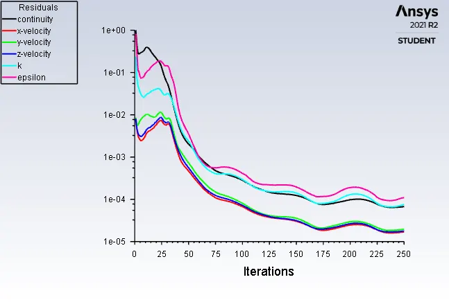
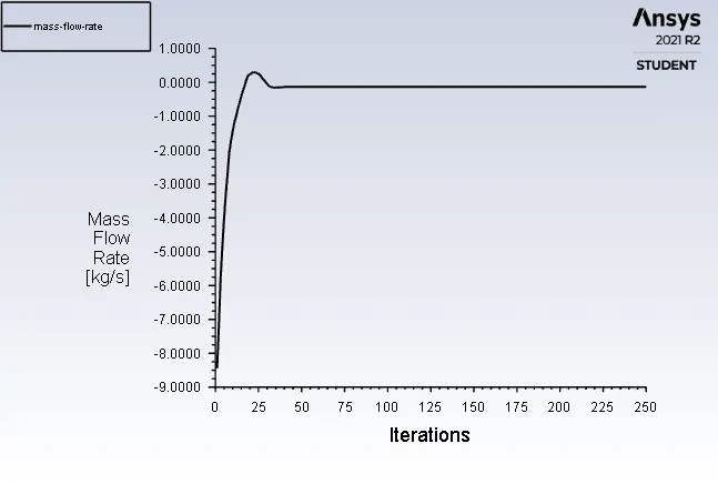
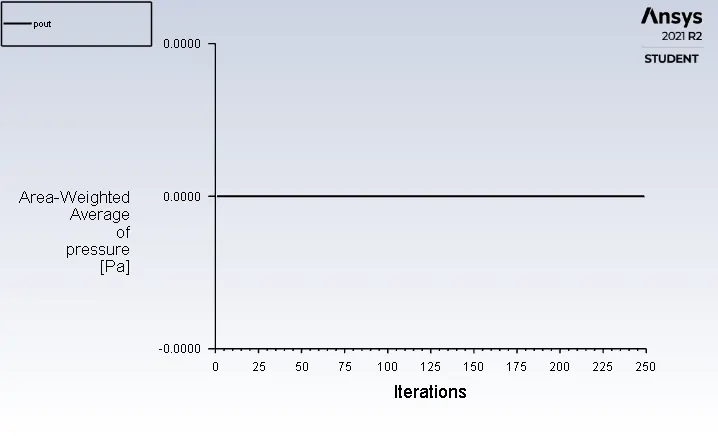
Mass Flow Rate:-
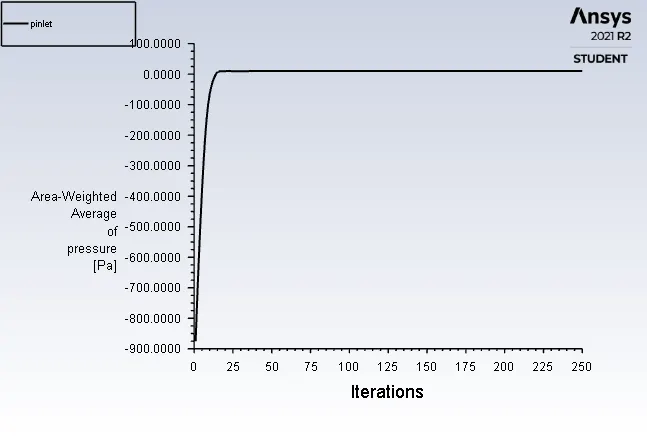
Pressure at Inlet:-
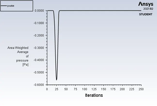
Pressure at Outlet:-
Results in CFD post:-
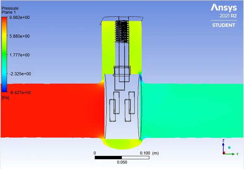
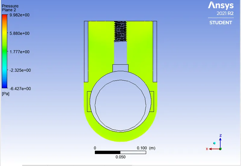
Pressure Contours:-
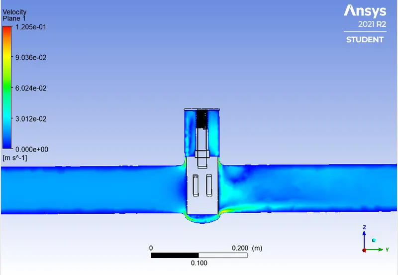
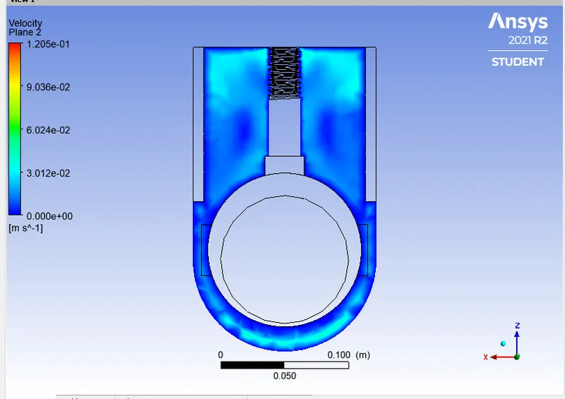
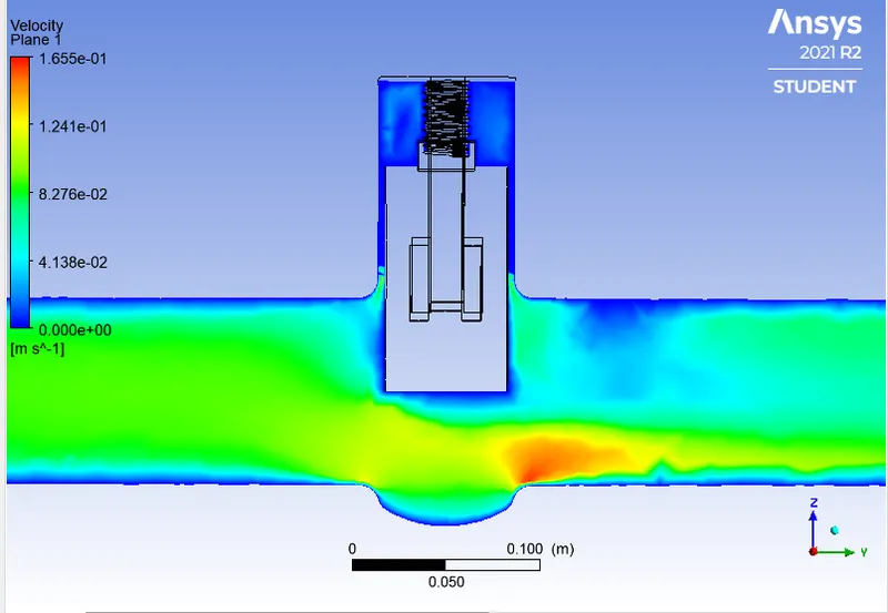
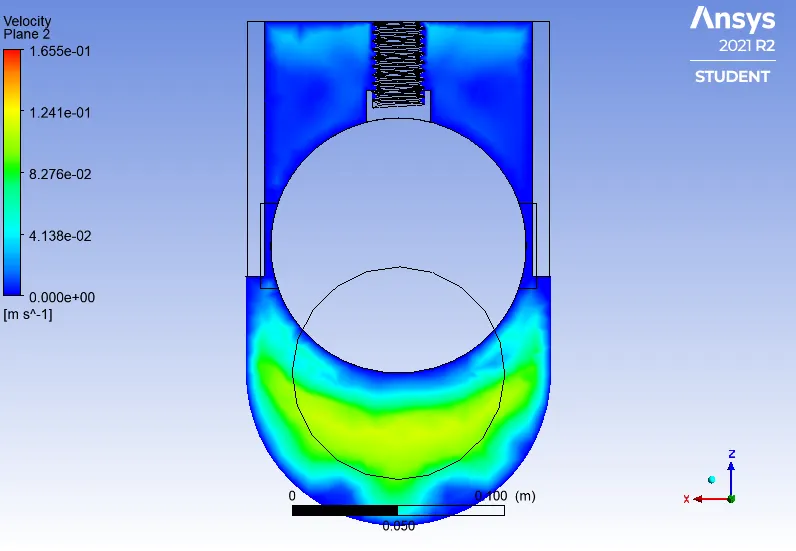
Velocity Contours:-
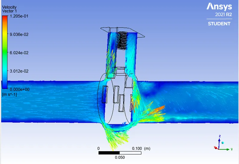
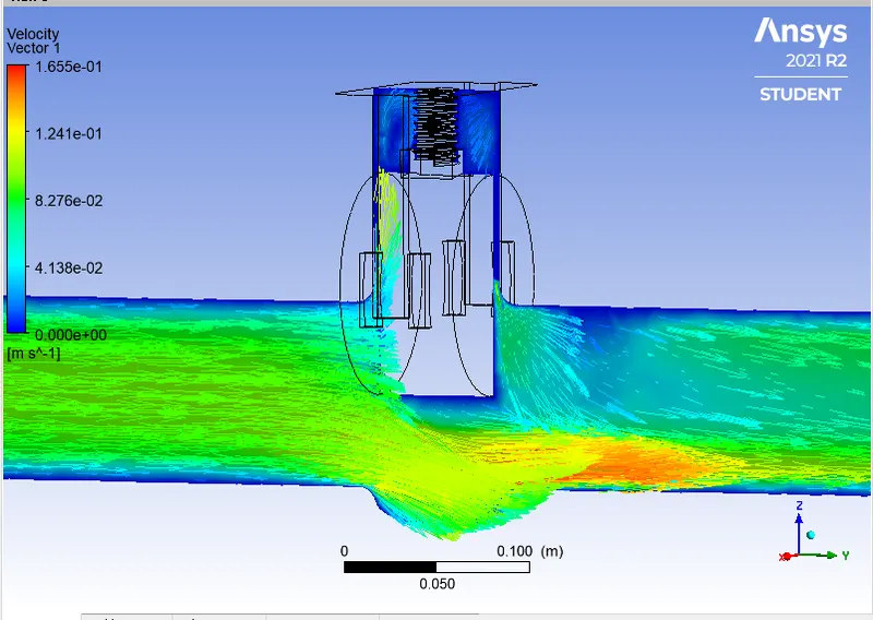
Velocity Vectors:-
Calculation:-

Q = 0.13363 kg/sec Convert it into Galoons/min; 1 kg/sec = 15.85 gal/min.
Q = 2.11850355 gal/min.
Pressure at Inlet = 9.851 Pascal, Pressure at Oulet = 0 Pascal. Then Pressure Drop = Pin-Pout => 9.851 Pascal convert it into Psi 1 Pascal = 0.000145 psi.
Pressure Drop(∆P) = 0.0014287 psi.
SG = 1 for water.
Cv = 56.035
Kv = 0.865*Cv
Kv = 48.47
For Case2: Dp1 20%
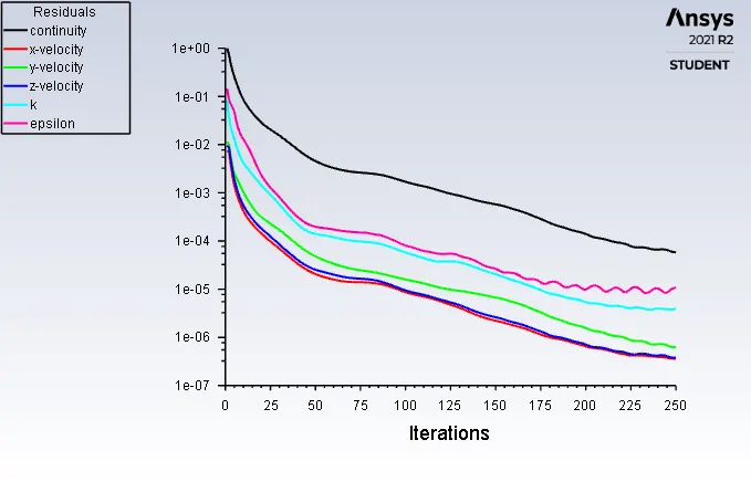
Residuals:-
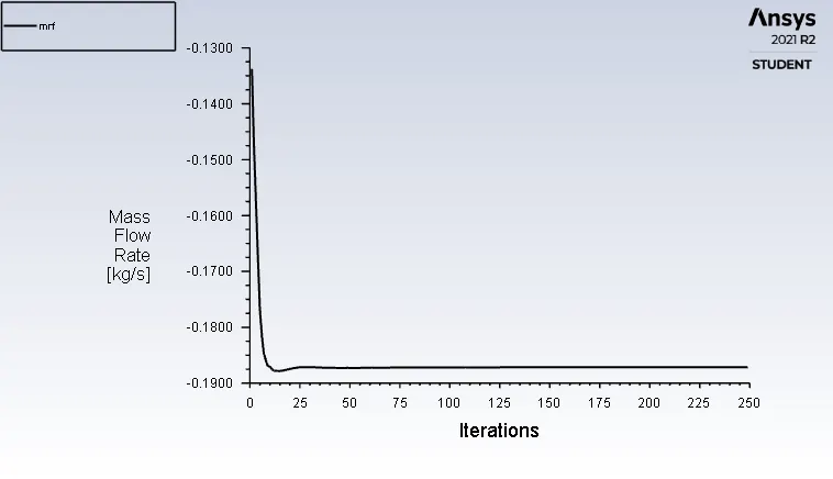
Mass Flow Rate:-
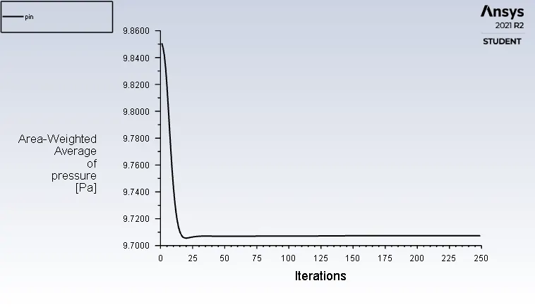
Pressure at Inlet:-
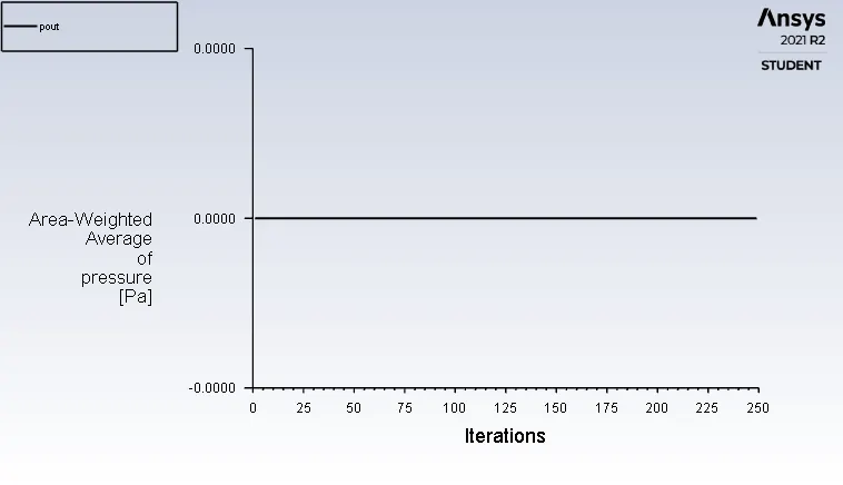
Pressure at Outlet:-
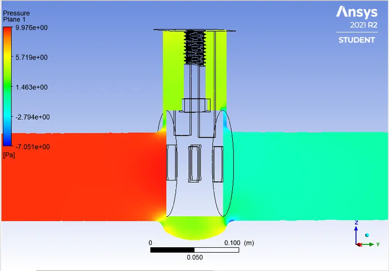
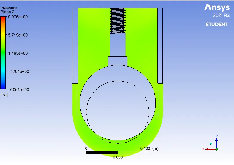
Pressure Contours plane:-
Velocity Contours:-
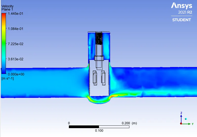
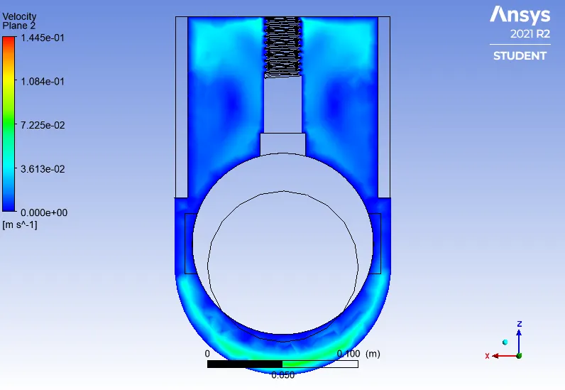
Velocity Contours:-
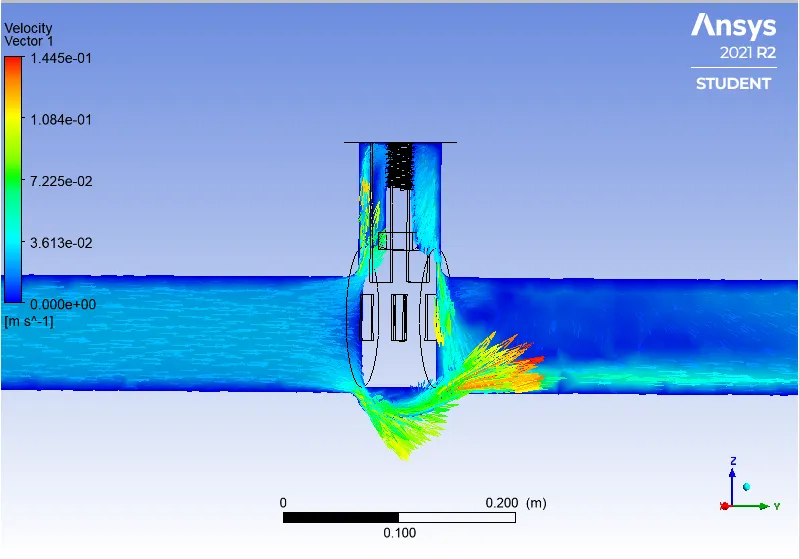
Q =0.18713 kg/sec Convert it into Galoons/min; 1 kg/sec = 15.85 gal/min.
Q = 2.9660 gal/min.
Pressure at Inlet = 9.851 Pascal, Pressure at Oulet = 0 Pascal. Then Pressure Drop = Pin-Pout =>9.7073 Pascal convert it into Psi 1 Pascal = 0.000145 psi.
Pressure Drop(∆P) = 0.00140755 psi.
SG = 1 for water.
Cv = 79.056
Kv = 0.865*Cv
Kv = 68.38
For Case3: Dp2 30%
Residuals:-
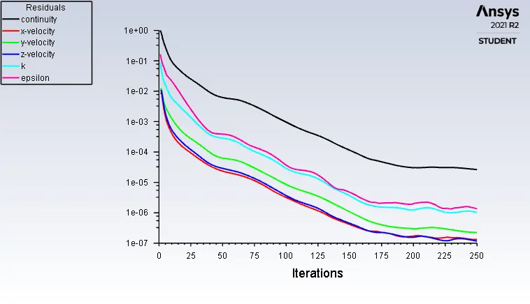
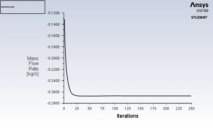
Mass Flow Rate:-
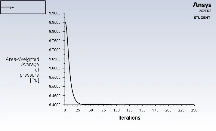
Pressure at Inlet
Pressure at Outlet
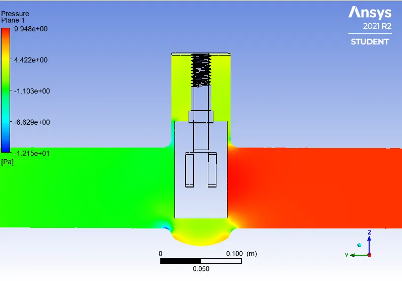
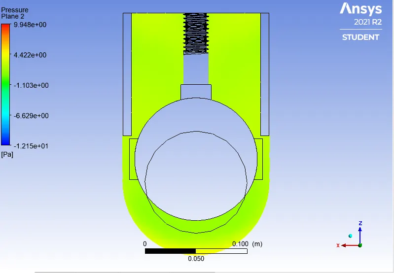
Pressure Contours:-
Velocity contours:-
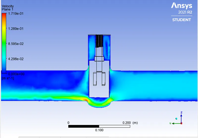

Velocity Vector:-
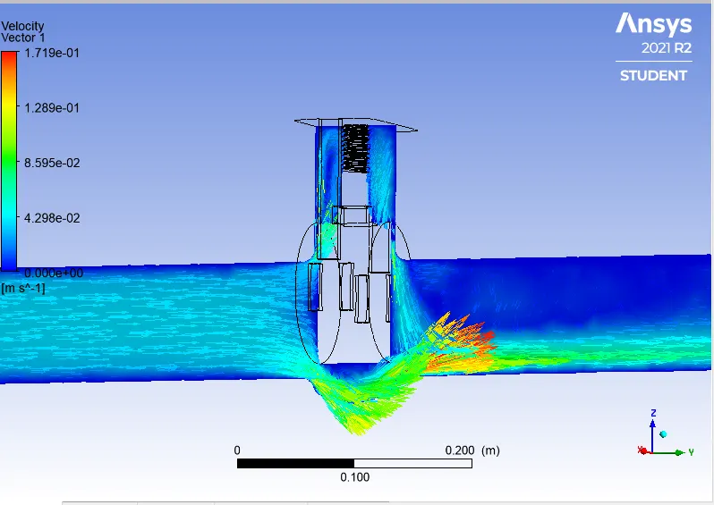
Q = 0.26709kg/sec Convert it into Galoons/min; 1 kg/sec = 15.85 gal/min.
Q = 4.2333765 gal/min.
Pressure at Inlet = 9.851 Pascal, Pressure at Oulet = 0 Pascal. Then Pressure Drop = Pin-Pout => 9.4034 Pascal convert it into Psi 1 Pascal = 0.000145 psi.
Pressure Drop(∆P) = 0.0013634 psi.
SG = 1 for water.
Cv = 114.650
Kv = 0.865*Cv
Kv =99.1725
Case4: dp3 40%
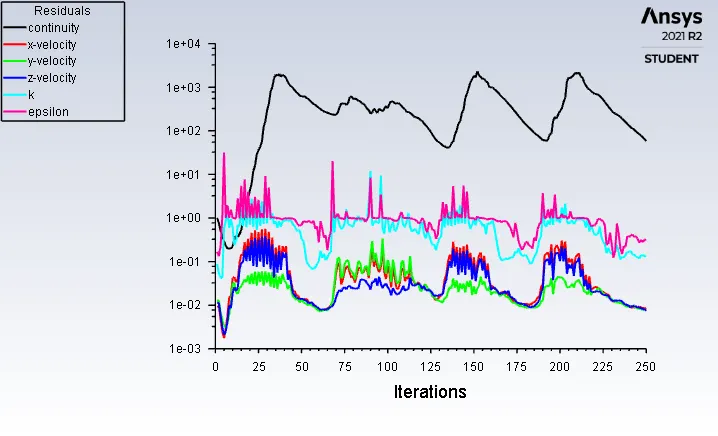
Residuals:-
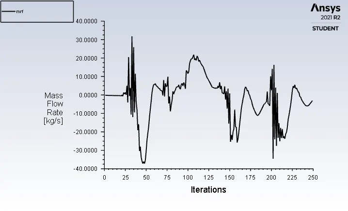
Mass Flow Rate:-
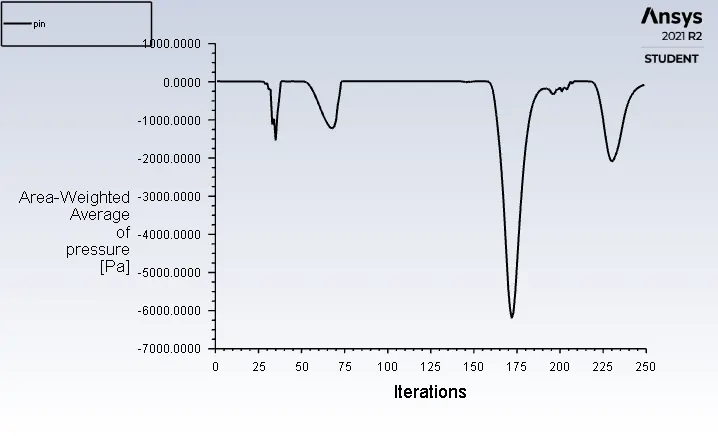
Pressure at Inlet:-
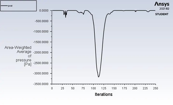
Pressure at Outlet:-
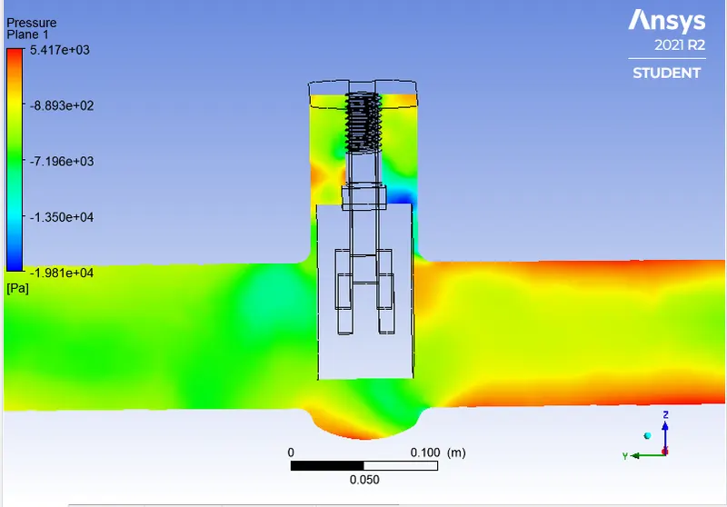
Pressure contours:-
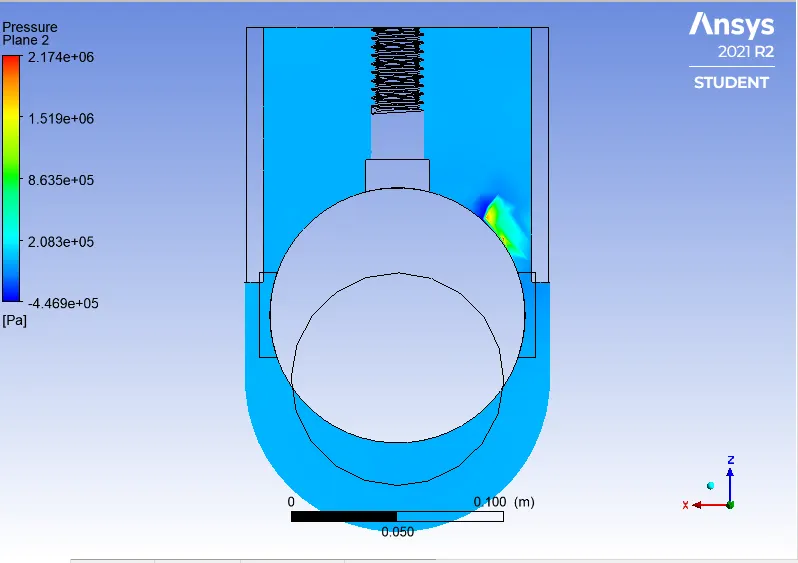
Velocity Contours:-
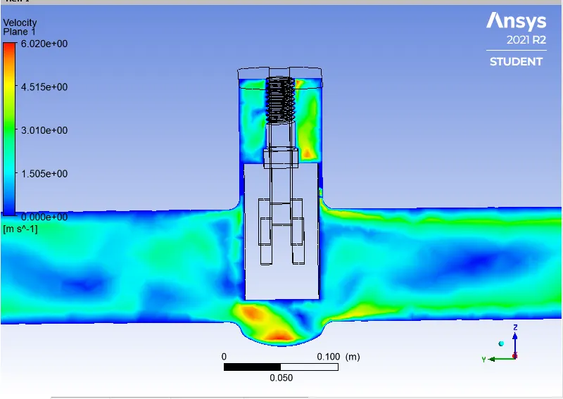
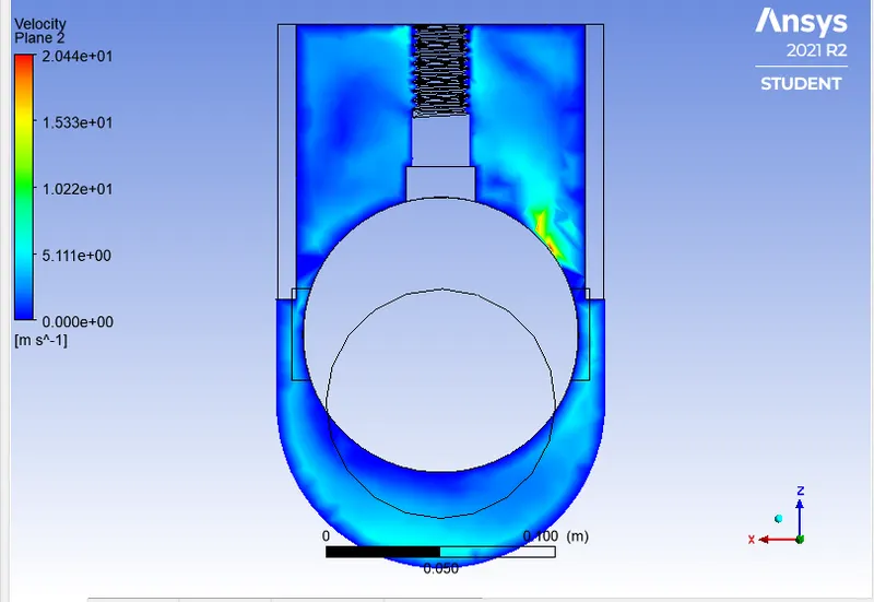
Velocity Vector:-
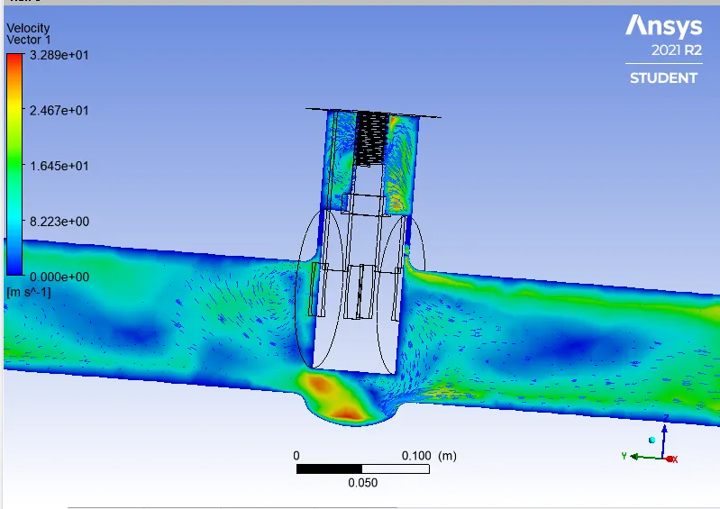
Q = 2.5848kg/sec Convert it into Galoons/min; 1 kg/sec = 15.85 gal/min.
Q = 40.96908gal/min.
Pressure at Inlet = 9.851 Pascal, Pressure at Oulet = 0 Pascal. Then Pressure Drop = Pin-Pout =>-67.48 Pascal convert it into Psi 1 Pascal = 0.000145 psi.
Pressure Drop(∆P) = 0.0097846 psi.
SG = 1 for water.
Cv =414.17575
Kv = 0.865*Cv
Kv = 358.262
Case5: dp4 50%
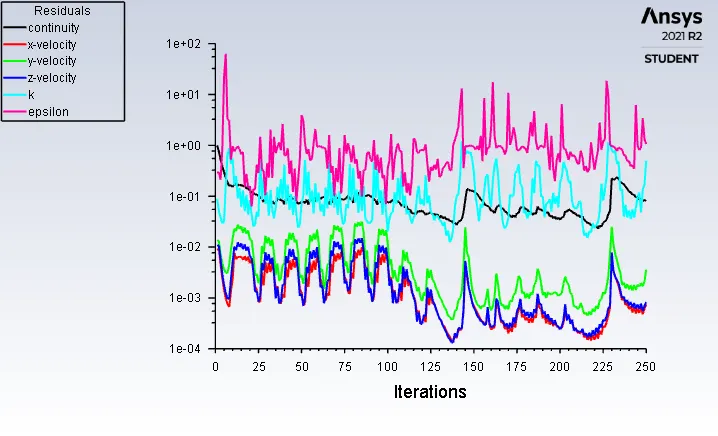
Residuals:-
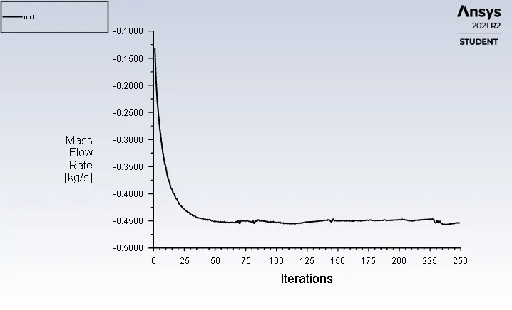
Mass Flow Rate:-
Pressure at Inlet:-
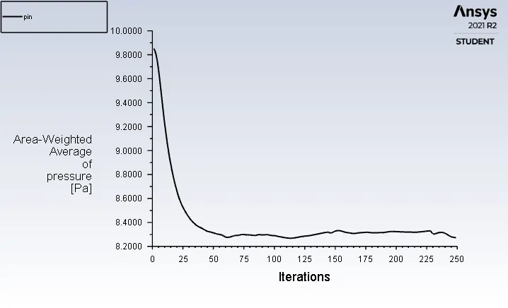
Pressure at Outlet:-
Pressure Contours:-
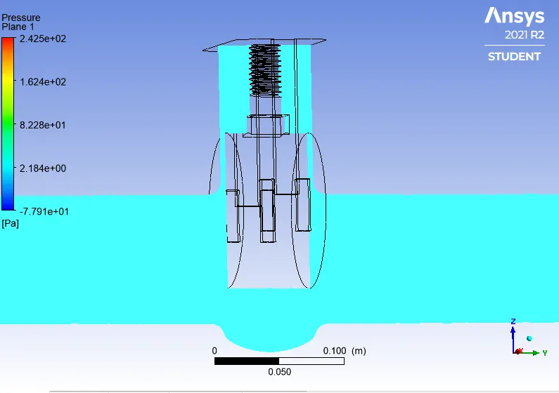
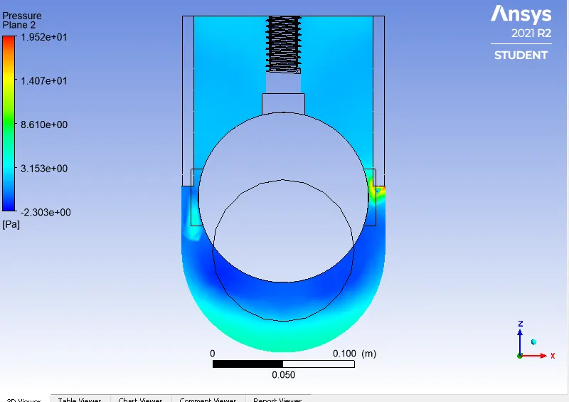
Velocity Contours:-
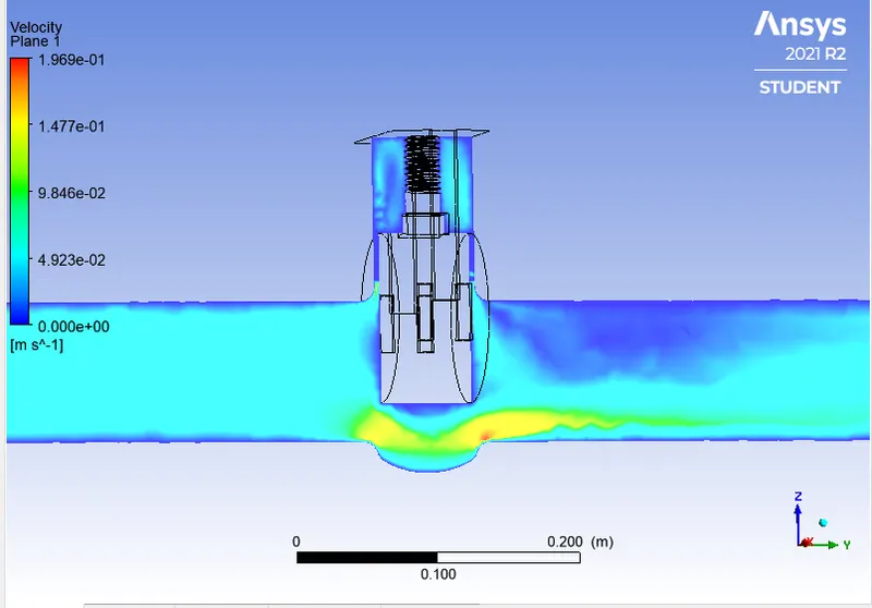
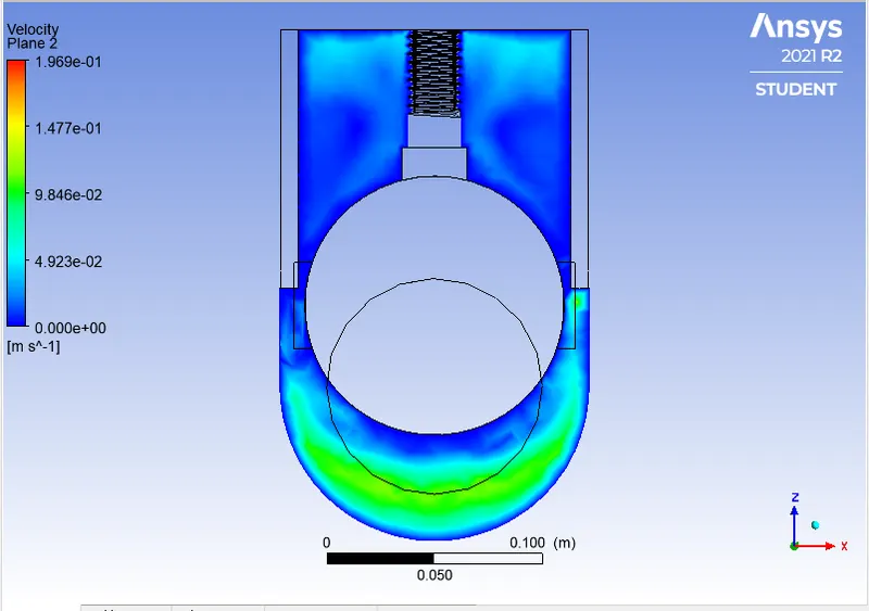
Velocity vector:-
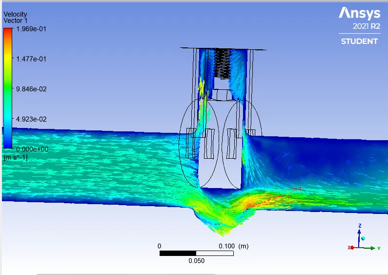
Q = 0.45277kg/sec Convert it into Galoons/min; 1 kg/sec = 15.85 gal/min.
Q = 7.17640gal/min.
Pressure at Inlet = 9.851 Pascal, Pressure at Oulet = 0 Pascal. Then Pressure Drop = Pin-Pout => 8.2745 Pascal convert it into Psi 1 Pascal = 0.000145 psi.
Pressure Drop(∆P) = 0.0011998 psi.
SG = 1 for water.
Cv = 207.1820
Kv = 0.865*Cv
Kv = 179.212
Case6: dp5 60%
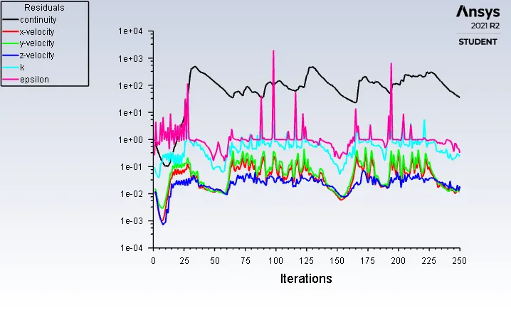
Residuals:-
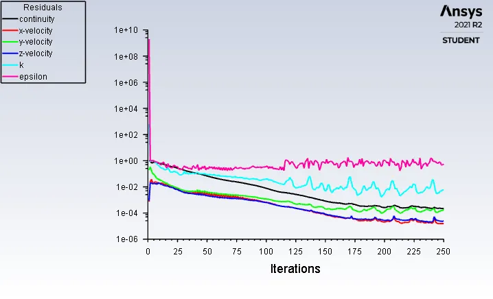
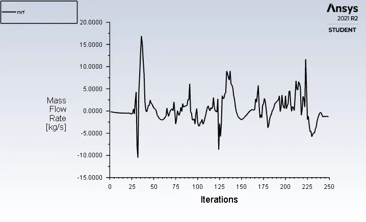
Mass Flow Rate:-
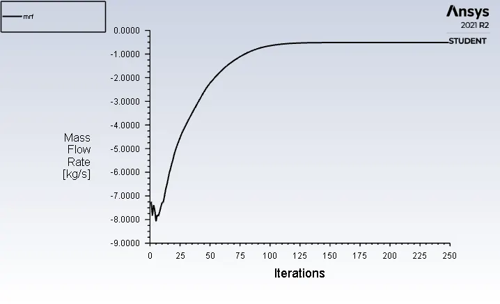
Pressure at Inlet:-
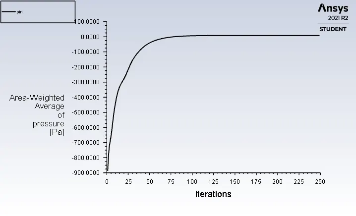
Pressure at Outlet:-
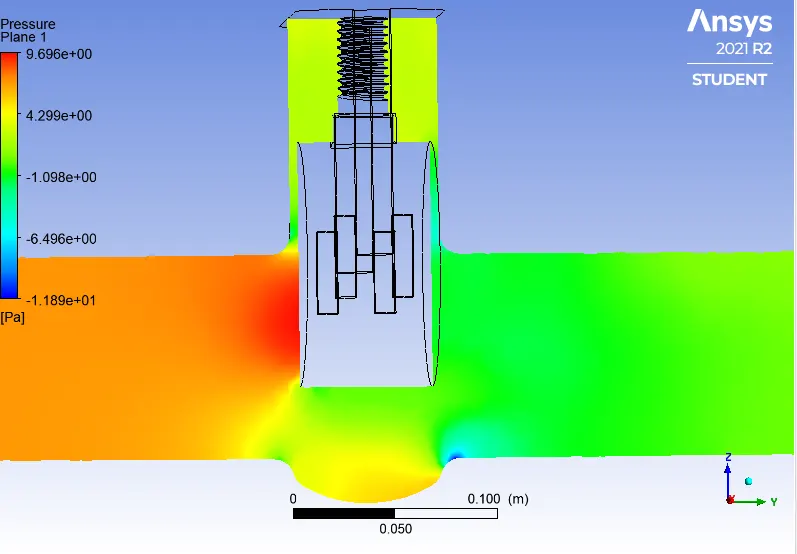
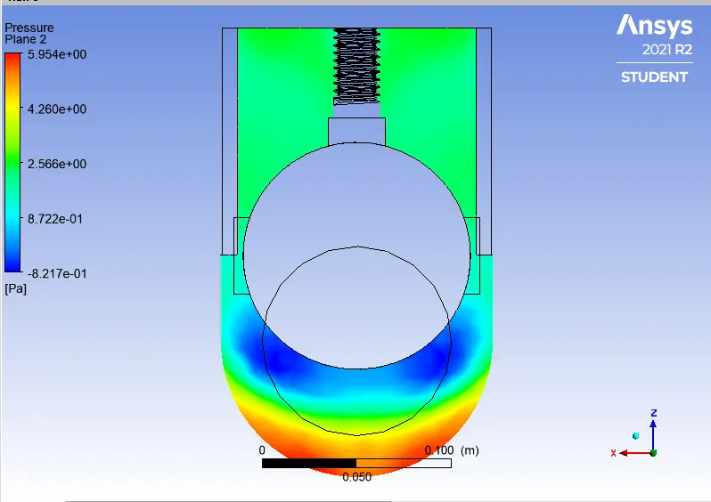
Pressure Contours:-
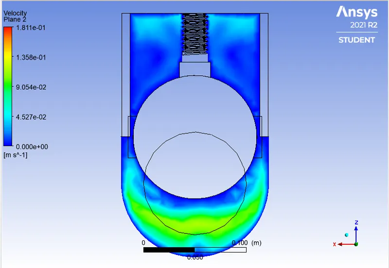
Velocity contours:-
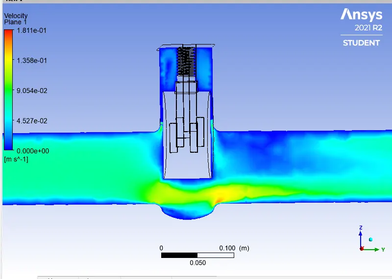
Velocity Vectors:-
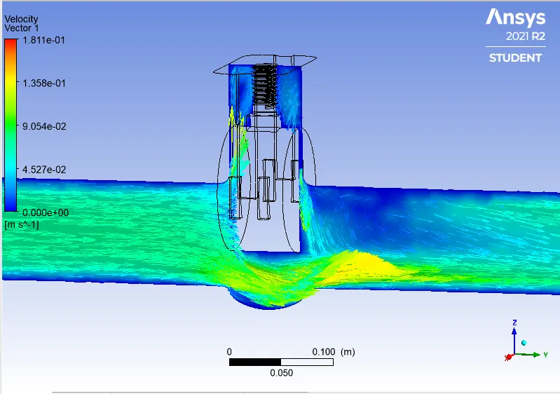
Q =0.51134 kg/sec Convert it into Galoons/min; 1 kg/sec = 15.85 gal/min.
Q = 8.104739 gal/min.
Pressure at Inlet = 9.851 Pascal, Pressure at Oulet = 0 Pascal. Then Pressure Drop = Pin-Pout => 7.8165 Pascal convert it into Psi 1 Pascal = 0.000145 psi.
Pressure Drop(∆P) = 0.0011333925 psi.
SG = 1 for water.
Cv = 240.740
Kv = 0.865*Cv
Kv = 208.240
Case7: dp6 70%
Residuals:-
Mass Flow Rate:-
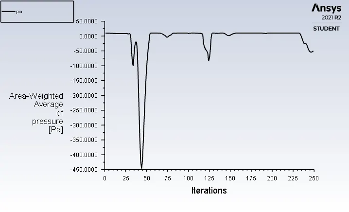
Pressure at Inlet:-
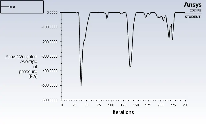
Pressure at Outlet:-
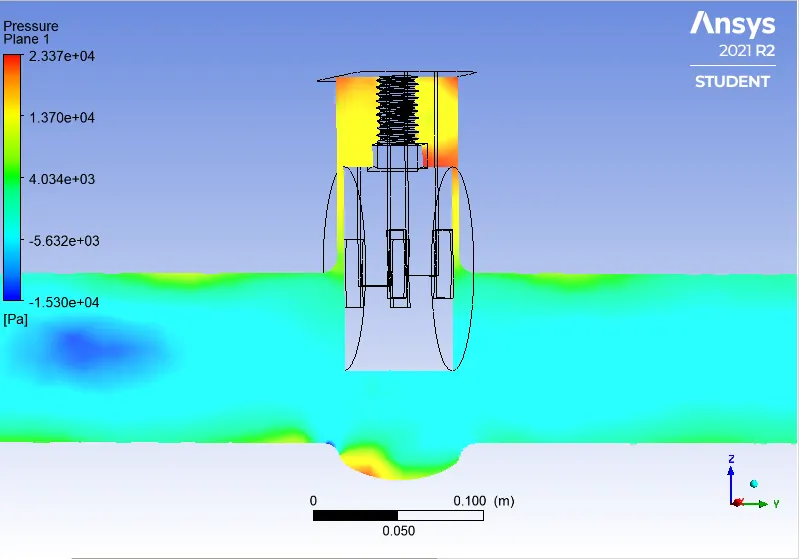
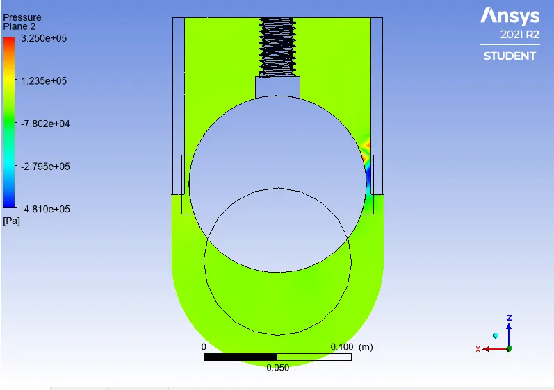
Pressure Contours:-
Velocity Contours:-
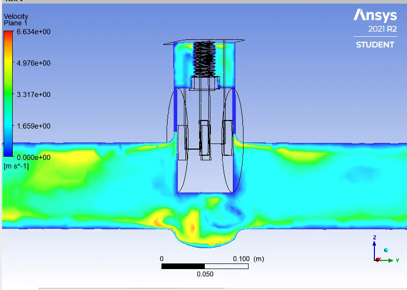
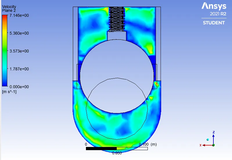
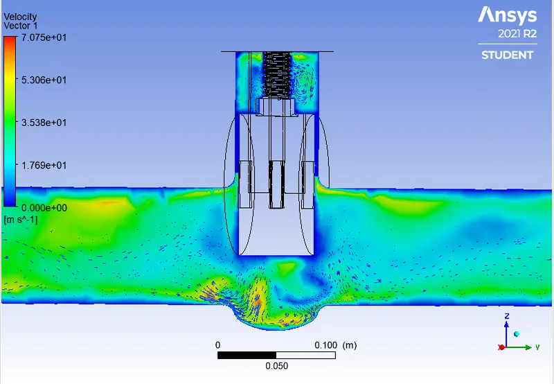
Velocity vector:-
Q =1.421 kg/sec Convert it into Galoons/min; 1 kg/sec = 15.85 gal/min.
Q = 22.52285 gal/min.
Pressure at Inlet = 9.851 Pascal, Pressure at Oulet = 0 Pascal. Then Pressure Drop = Pin-Pout =>-46.328 Pascal convert it into Psi 1 Pascal = 0.000145 psi.
Pressure Drop(∆P) = 0.00671756 psi.
SG = 1 for water.
Cv = 274.800
Kv = 0.865*Cv
Kv = 237.702
Case8: dp7 80%
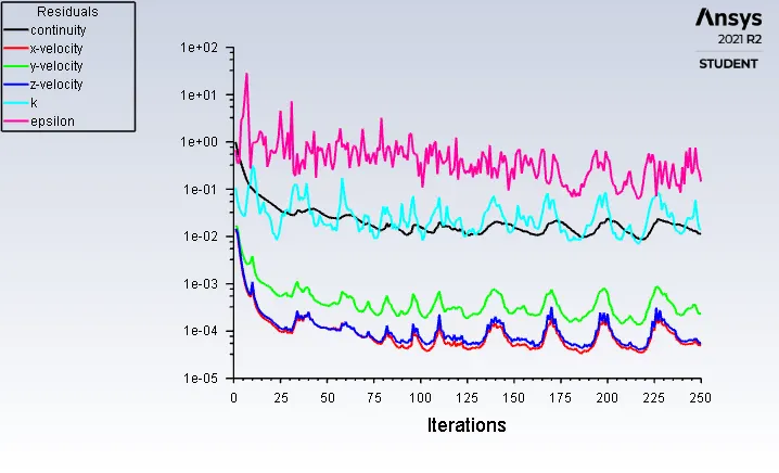
Residuals:-
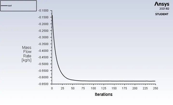
Mass Flow Rate:-
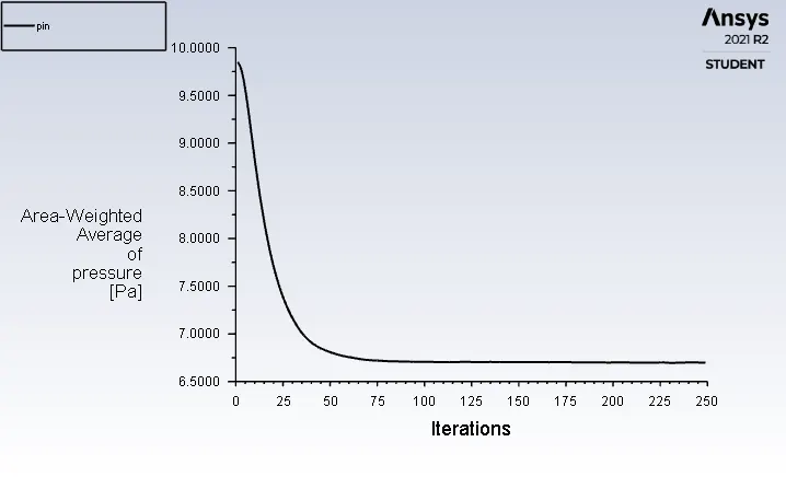
Pressure at Inlet:-
Pressure at Outlet:-
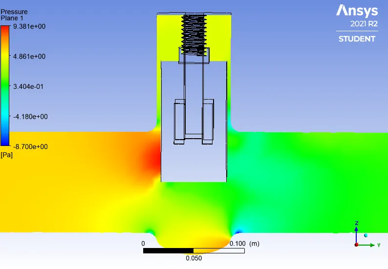
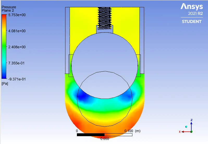
Pressure Contours:-
Velocity contours:-
Velocity vectors:-
Q = 0.62839 kg/sec Convert it into Galoons/min; 1 kg/sec = 15.85 gal/min.
Q = 9.95998 gal/min.
Pressure at Inlet = 9.851 Pascal, Pressure at Oulet = 0 Pascal. Then Pressure Drop = Pin-Pout =>6.6991 Pascal convert it into Psi 1 Pascal = 0.000145 psi.
Pressure Drop(∆P) = 0.00097136 psi.
SG = 1 for water.
Cv = 319.571
Kv = 0.865*Cv
Kv = 276.429
---------------------------------------------------------------------------------------------------------------------------------------------
OBSERVATIONS:-
| Cases | Percentage of Opening | Gate Disc Lift (in mm) | Mass Flow Rate (kg/sec) | Flow coefficient (Cv) | Flow Factor (Kv) |
| Dp0 | 10% | 7.5 | 0.13363 | 56.035 | 48.47 |
| Dp1 | 20% | 15 | 0.18713 | 79.056 | 68.36 |
| Dp2 | 30% | 22.5 | 0.26709 | 114.65 | 99.17 |
| Dp3 | 40% | 30 | 2.5848 | 414.17 | 358.62 |
| Dp4 | 50% | 37.5 | 0.45277 | 207.18 | 179.21 |
| Dp5 | 60% | 45 | 0.51134 | 240.74 | 208.24 |
| Dp6 | 70% | 52.5 | 1.421 | 274.80 | 237.70 |
| Dp7 | 80% | 60 | 0.62839 | 319.57 | 276.42 |
Graph Between Flow coefficient (Cv) and Flow factor (Kv) for each Opening:-
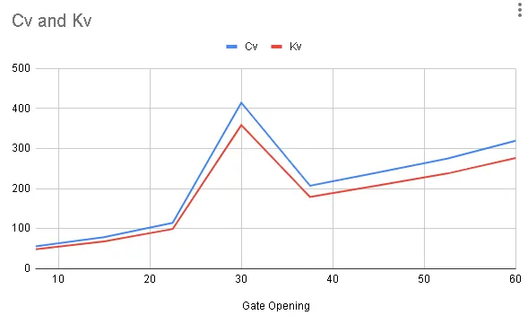
- X-axis shows the Gate opening or the Lift of the Gate Valve (in mm) and Y-axis Shows the Flow coefficient (Cv) and Flow factor (Kv) for each Opening of the Gate disc.
- From the above Plot we can conclude that the As the opening of the Gate valve increases, Mass flow rate is also increases.
- As the Mass flow rate inceases, Flow coefficient is also increases.
- With the increament in the Flow coefficient Flow factor is also increased, So Graph shows that the Relationship of Mass flow rate, Flow coefficient and Flow factor.
Conclusion:-
- We can conclude that As the Opening is increases the Mass flow rate is also increases, Flow coefficient and Flow factor also with respective.
- Pressure at Inlet side is high So, flow Passes through the valve opening it decrease and Pressure at Outlet is not restricted to the Flow, so it is 0 gauge Pressure.
- When the valve is fully open Mass flow rate is should be maximum.
- Thus, parametric Study helps to analyze the different positions of valve opening and gives the benifit to get easily and quick results.