Week 9 - Parametric study on Gate valve.
Aim: To perform a parametric study on the gate valve simulation by setting the opening from 10% to 80%.
Introduction:
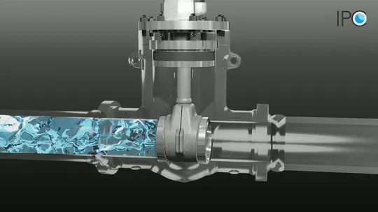
Gate Valve, also known as a sluice valve, is a valve that opens by lifting a round or rectangular gate or wedge out of the path of the fluid. The distinct feature of a gate valve is the sealing surfaces between the gate and seats are planar, so gate valves are often used when a straight-line flow of fluid and minimum restriction is desired. The gate faces can form a wedge shape or they can be parallel. Gate valves are primarily used to permit or prevent the flow of liquids, but typical gate valves shouldn't be used for regulating flow unless they are specifically designed for that purpose. Flow-through a gate valve is not proportional to the amount the gate valve is opened, that is the main reason gate valves are poorly suited to throttling. If the valve is throttled, the flow through the valve has a very turbulent and high velocity, this leads to seat and disc wear.
Gate valves offer almost no resistance to flow when they are in the open position; consequently, the pressure differential across the valve is very low when the valve is open. On opening the gate valve, the flow path is enlarged in a highly nonlinear manner with respect to per cent of opening. This means that the flow rate does not change evenly with stem travel. Also, a partially open gate disk tends to vibrate from the fluid flow. Most of the flow change occurs near shutoff with a relatively high fluid velocity causing disk and seat wear and eventual leakage if used to regulate flow. Typical gate valves are designed to be fully opened or closed. When fully open, the typical gate valve has no obstruction in the flow path, resulting in very low friction loss.
Gate valves are characterised as having either a rising or a non-rising stem. Rising stems provide a visual indication of valve position because the stem is attached to the gate such that the gate and stem rise and lower together as the valve is operated. Non-rising stem valves may have a pointer threaded onto the upper end of the stem to indicate valve position since the gate travels up or down the stem on the threads without raising or lowering the stem. Non-rising stems are used underground or where vertical space is limited. Bonnets provide leakproof closure for the valve body. Gate valves may have a screw-in, union, or bolted bonnet. Screw-in bonnet is the simplest, offering a durable, pressure-tight seal. Union bonnet is suitable for applications requiring frequent inspection and cleaning. It also gives the body added strength. Bolted bonnet is used for larger valves and higher-pressure applications. Another type of bonnet construction in a gate valve is pressure seal bonnet. This construction is adopted for valves for high-pressure service, typically in excess of 15 MPa. The unique feature about the pressure seal bonnet is that the body-bonnet joints seals improve as the internal pressure in the valve increases, compared to other constructions where the increase in internal pressure tends to create leaks in the body-bonnet joint. Gate valves may have flanged ends which are drilled according to pipeline compatible flange dimensional standards.
Gate Valve Construction and Working Principle:
A gate valve’s main components are the bonnet, disc, seat, sealing arrangement (gland seal, stuffing box etc.), stem, body and actuator.
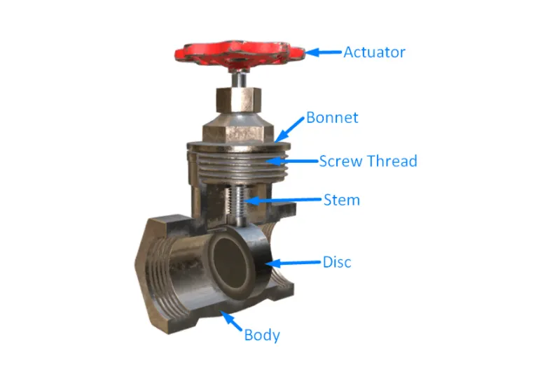
Gate valves can be actuated manually (handwheel) or electrically using a high torque motor.
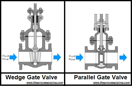
The disc can be wedge-shaped (tapered) or parallel shaped. Wedge shape designs include solid, flexible and split wedge designs.
Seat rings are used to make the replacement of a worn/leaking seat easier. Seat rings have a screw thread on the reverse side which can be screwed into the main valve body, the flat surface on the opposite side is the seating surface area that presses against the disc. If seat rings are not used, it is possible to machine a flat seat on the main valve body itself, unfortunately, this makes replacing the seat impossible and the seat can only be machined a few times before the entire valve must be replaced.
Gate valve bonnets are often constructed of cast iron. Cast iron is brittle and this makes the bonnet prone to cracking. Special care should be taken when handling and maintaining valves with cast iron bonnets.
As the steam penetrates through the valve bonnet, it is necessary to install a sealing gland to prevent leakage occurring through the gap between the stem and bonnet; sealing is usually achieved using the fibrous packing material. Flanges are installed on the suction and discharge side of the valve so that piping can be easily connected.
The main operation mechanism is very simple. When the hand-wheel is turned, it rotates the stem, which is translated into the vertical movement of a gate via threads. They are considered multi-turn valves as it takes more than one 360° turn to fully open/close the valve. When the gate is lifted from the path of the flow, the valve opens and when it returns to its closed position, it seals the bore resulting in a full closure of the valve.
Gate Valve Closing Member Design:
There are usually two types of gate valve closing members(gate) which are having further varieties.
- Parallel Gate Valve – Use a flat gate between two parallel seats.
Conventional Parallel Gate
Through-Conduit Gate
Knife Gate
- Wedge Gate Valve – Use a slightly mismatched inclined gate between inclined seats.
Solid Taper Wedge
Split Wedge
Flexible Wedge
Gate Valve Stem Design:
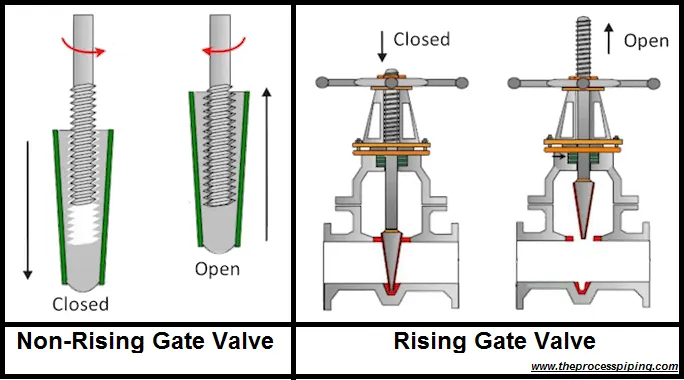
Gate valves are characterised as having either a rising or a non-rising stem. The stem, which connects the hand-wheel and disk with each other, is responsible for the proper positioning of the disk. Stems are usually forged, and connected to the disk by threaded or other techniques. Depending on which end of the stem is threaded, stems can be rising or non-rising.
Rising Stem Gate Valve:
Rising stems are fixed to the gate and they rise and lower together as the valve is operated, providing a visual indication of the valve position and making it possible to grease the stem. A nut rotates around the threaded stem and moves it. This type of valve has an inside screwed stem and the packing is subjected to wear because of the up and down movement and turning motion of the stem. This type is only suitable for above-ground installation.
Non-Rising Stem Gate Valve:
Non-rising stems are threaded into the gate and rotate with the wedge rising and lowering inside the valve. Rotation of the wheel operates the valve, but the stem does not come out of the housing. They take up less vertical space since the stem is kept within the valve body. Non-rising valves are almost always fitted with a local visual pointer which indicates the position of the valve. Gate valves with non-rising stems are suitable for both above-ground and underground installations.
Geometry:
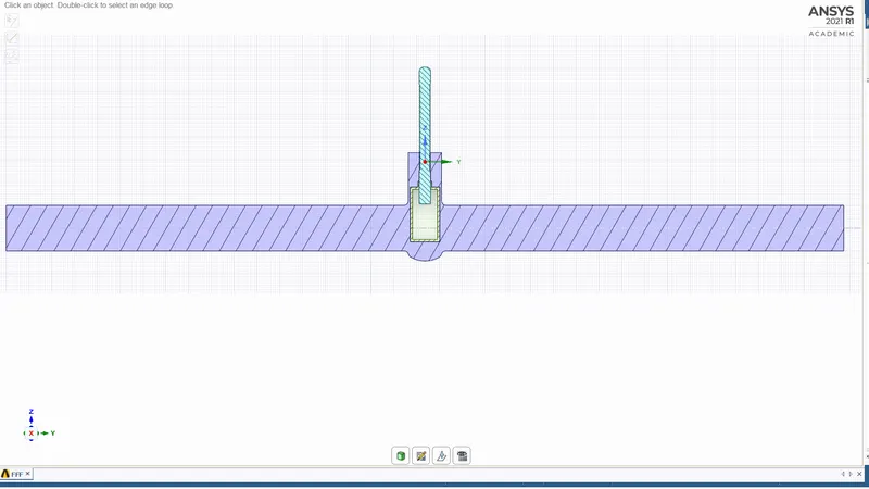
The 3D model of the gate valve is imported to Spaceclaim.
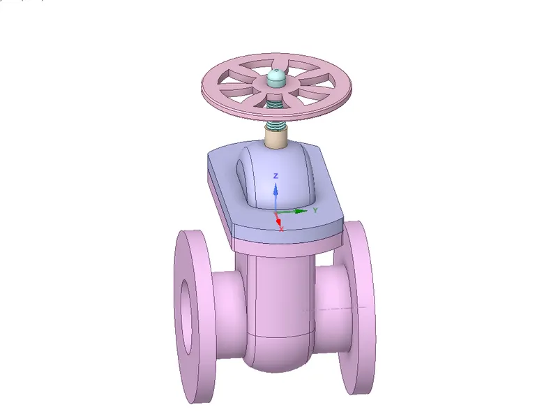
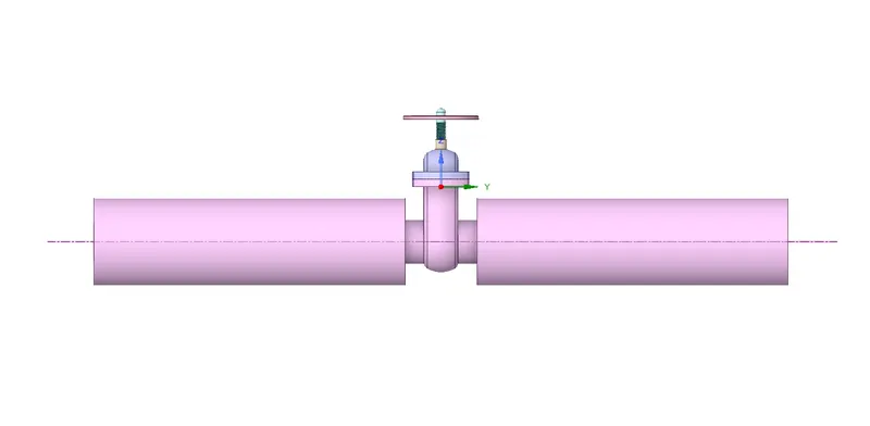
With the help of the Pull tool, the volume available for flow is increased. This is done by pulling the surface of the solid on both sides by 800mm.
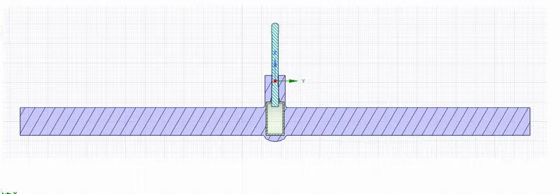
Extraction of fluid volume is done by volume extraction.
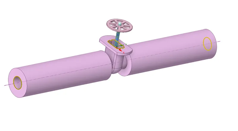
Extracted fluid volume
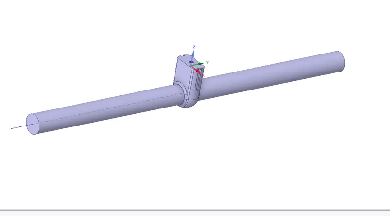
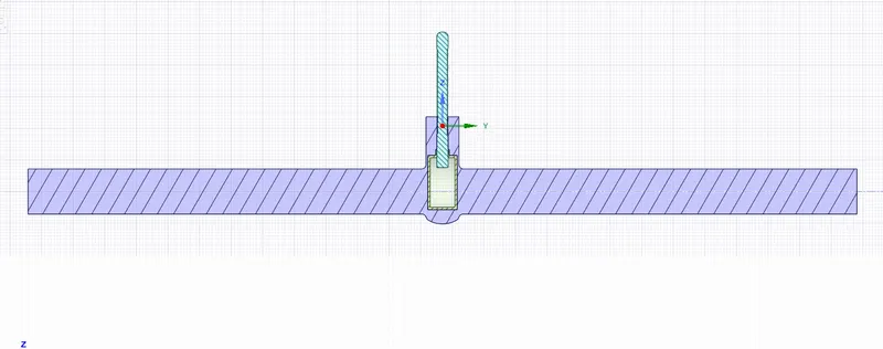
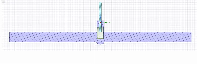
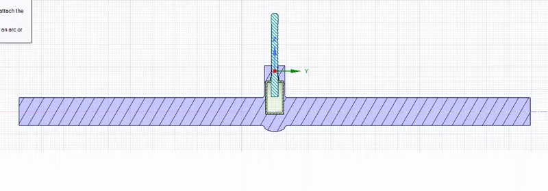
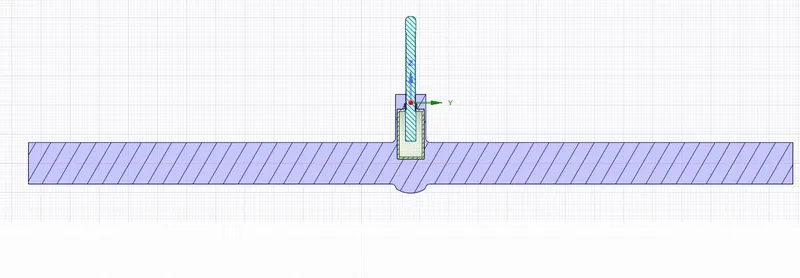
With the help of the move tool, The gate disc is moved upwards by giving 10mm as the initial lift distance. Then, the lift of the disc is set as a parameter.
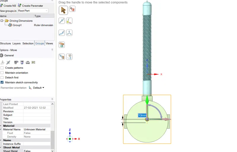
Update volume in context. While doing this the spindle should not be hidden.
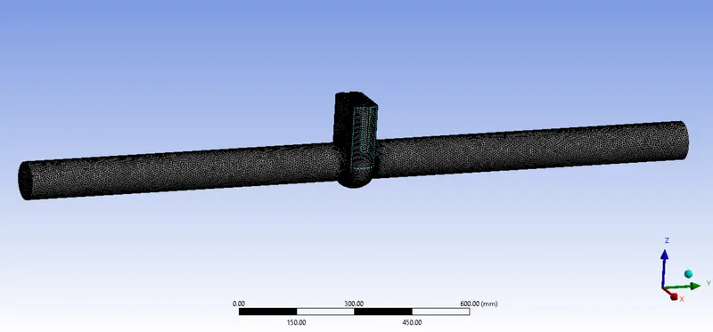
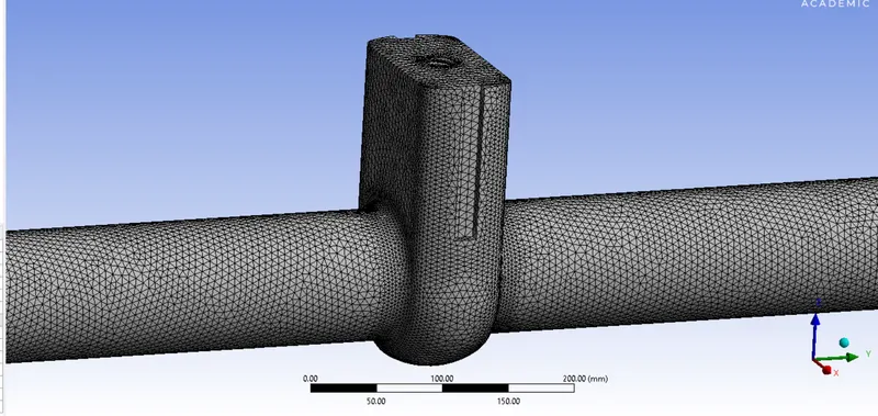
Meshing:
Number of elements:414478
Number of nodes: 83883
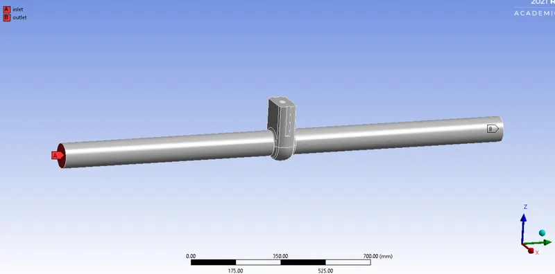
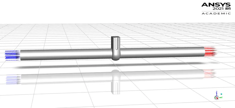
Named selection:
Mesh metric:
The mesh metric that identifies the elements according to their quality was employed and it can be seen that the elements of lowest quality are minimal, most of the elements have very high quality in the range of 0.8-1.

Setup:
Solver Type – Pressure based
Time – Steady
Gravitational acceleration (Z m⁄s^2) = -9.81
Viscous model – K-epsilon Realizable with scalable wall function
Material:
Water liquid
Density: 998.2 Kg/m^3
Viscosity: 0.001003 Kg/m-s
Cell zones – volume_volume -water liquid
Boundary conditions:
Inlet- Pressure inlet, Gauge pressure =10 Pa
Outlet – Pressure outlet, Gauge pressure= 0Pa
Report definition:
Flux report – Mass flow rate
‘Create output parameter’ option is checked along with report file, report plot, print to console.
Initialization – Standard initialization, compute from the inlet.
Number of iterations (for 10mm lift of gate disc) = 500
Solution:
For case 1: Gate disk lift = 10mm
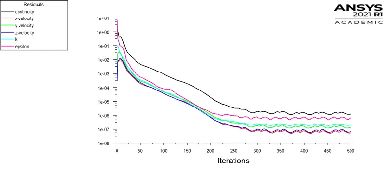
Residual plot
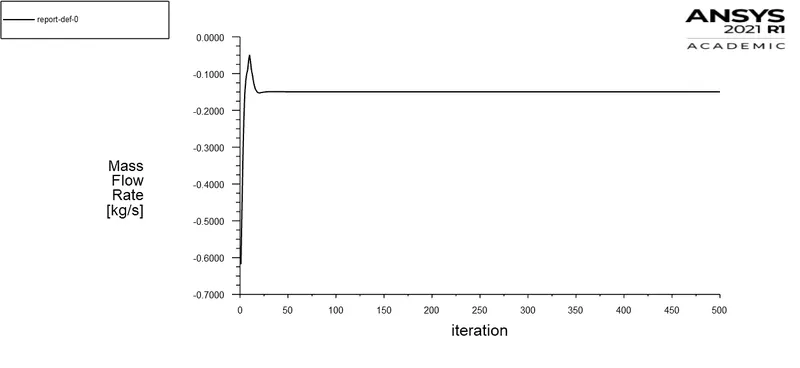
Mass flow rate plot:
Results:
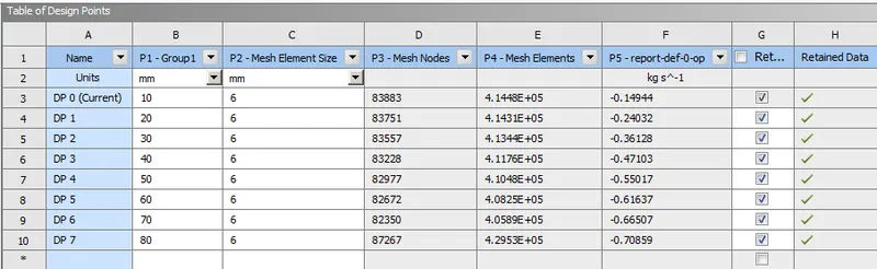
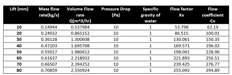
Mass flow rate for each design point:
Animation for 10mm lift of gate disc:
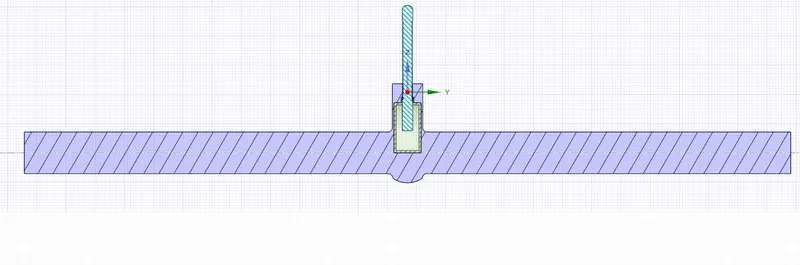
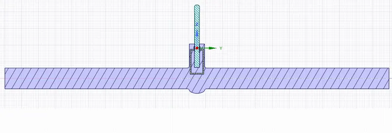
Gate disc lift:
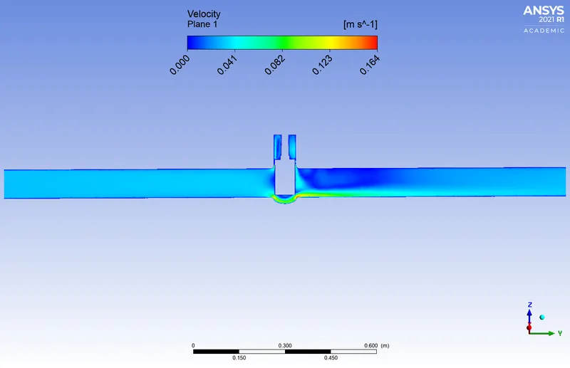
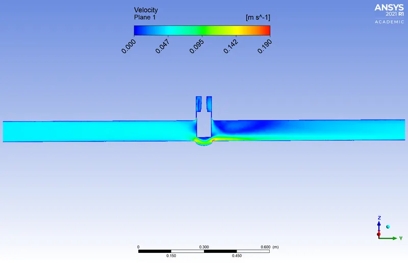
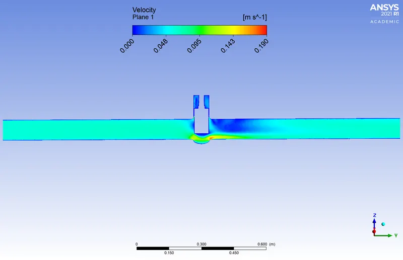
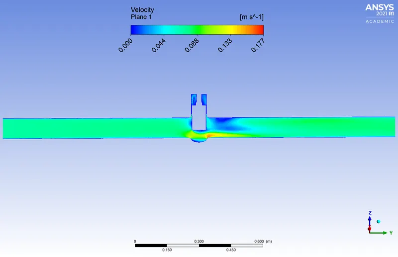
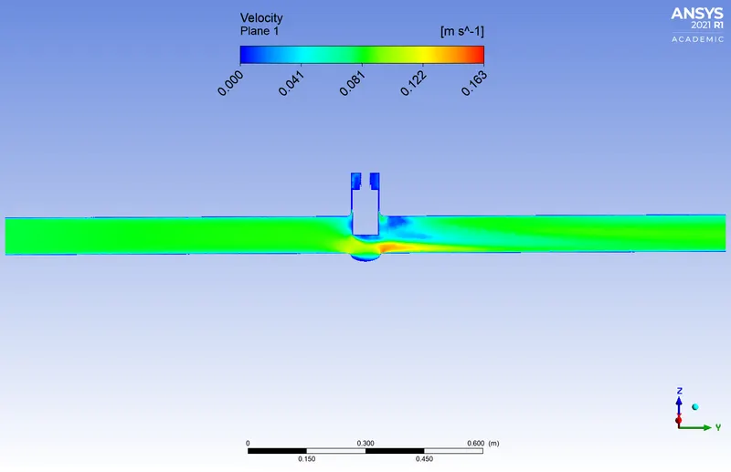
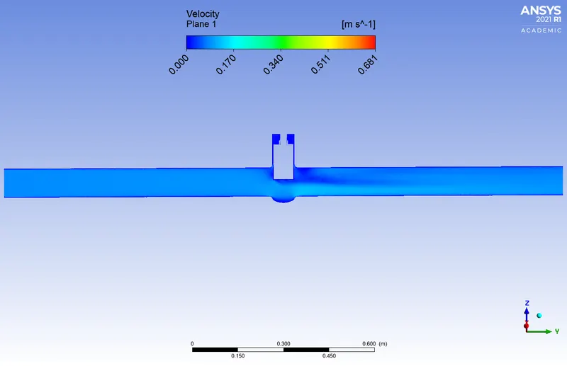
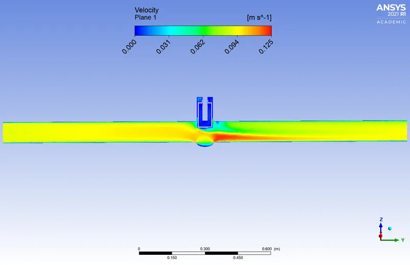
Velocity contour:
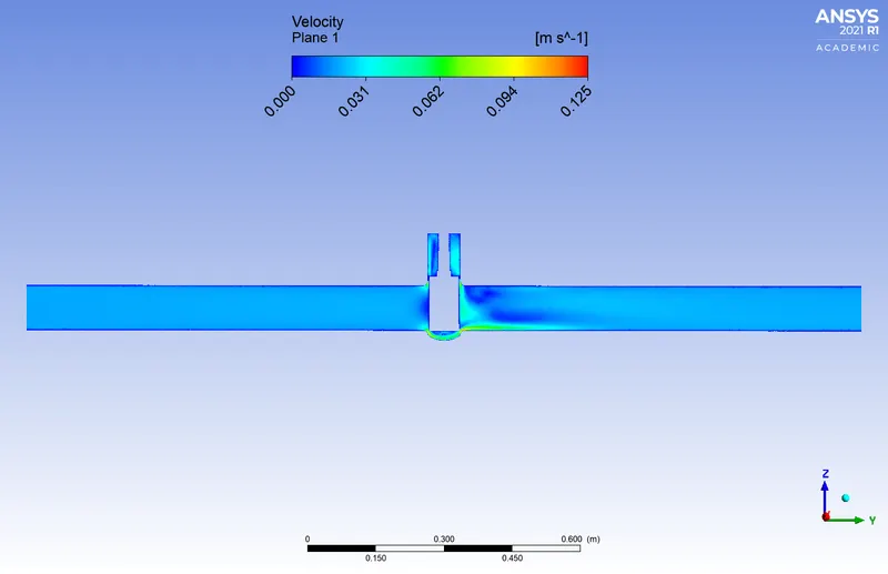
Velocity contour Gate disc lift
|
10mm
|
|
|
20mm
|
 |
|
30mm
|
|
|
40mm
|
 |
|
50mm
|
 |
|
60mm
|
|
|
70mm
|
 |
|
80mm
|
|
Flow coefficient, Cv:
A Flow Coefficient (Cv) is a relative measure of the fluid flow efficiency that is a designing factor that relates head drop (Δh) or pressure drop (ΔP) across the valve with the flow rate (Q). The Cv is the number of gallons of water per minute (gpm) that will flow through a valve or any other restricting device at a temperature of 60ºF with a pressure drop across the valve of 1 psi.
The definition of Cv is based on water, which has a G (specific gravity) = 1.0. Fluids with other gravities will flow at different rates. For example, heavier fluids will have a greater pressure loss through the same valve passage. The viscosity of the fluid will also affect its flow rate through a valve. Fluids with higher viscosity will have a higher pressure drop than water.
Each valve has its own flow coefficient. This depends on how the valve has been designed to let the flow going through the valve. Therefore, the main differences between different flow coefficients come from the type of valve, and of course the opening position of the valve. Flow coefficient is important in order to select the best valve for a specific application. If the valve is going to be most of the time opened, probably there should be selected a valve with low head loss in order to save energy. Or if it is needed a control valve, the range of coefficients for the different opening positions of the valve should fit the requirements of the application.
At the same flow rate, a higher flow coefficient means lower drop pressure across the valve.
Depending on the manufacturer, type of valve, application the flow coefficient can be expressed in several ways. The coefficient can be non-dimensional or with units if parameters such as diameter or density are considered inside the coefficient or just in the equation.

Where,
Q is the rate of flow (expressed gallons per minute),
SG is the specific gravity of the fluid (for water = 1),
ΔP is the pressure drop across the valve (expressed in psi).
Flow factor, Kv:
The metric equivalent of the flow coefficient (Cv) is based on the SI-system and is called the Flow Factor - Kv

Q is the flow rate (expressed in m^3/s)
SG is the specific gravity of the fluid (for water = 1),
∆P is the differential pressure across the device (expressed in [bar]).
Conversion between Flow coefficient and Flow factor:
Cv = 1.156 Kv
Kv is the flow factor (m^3/hr) (bar)
Cv is the flow coefficient (gpm) (psi)
The mass flow rate obtained from the simulation will be in Kg/s.
We know,
Q = mass flow rate/ density of water
The density of water=1000Kg/m^3
Therefore, the unit of volumetric flow rate is m^3/s.
In order to convert m^3/s to m^3/hr, multiply Q by 3.6.
Graphs:
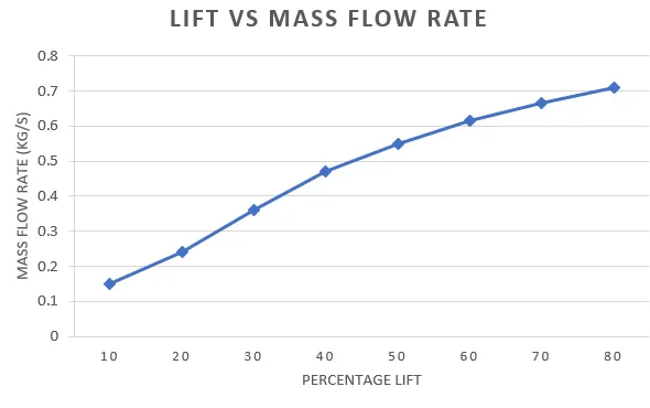
Gate disc lift (mm) vs Mass flow rate(kg/s):
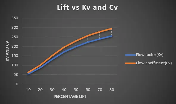
Gate disc lift (mm) vs Kv & Cv :
Conclusion:
Parametric study on the gate valve simulation by setting the opening from 10% to 80% under steady-state condition is performed and it is observed that the flow rate increase as the opening is increased from 10mm to 80mm and since the flow rate is increasing, we can also observe that the flow coefficients and flow factors increasing.
With the help of the parametric study, the solving time required in studying the effect of change of parameters on the system got reduced.