Week 9-Creation of 1D Connectors Challenge
AIM: to create 1D connectors
in this, we need to mesh the given component with the following criteria
|
S.N |
Quality Criteria |
Value |
|
1 |
Aspect Ratio |
5 |
|
2 |
Skewness |
45 |
|
3 |
Warping |
15 |
|
4 |
Taper |
0.5 |
|
5 |
Min. Length |
2 Units |
|
6 |
Max. Length |
8 Units |
|
7 |
Min angle Quad |
45 |
|
8 |
Max angle Quad |
135 |
|
9 |
Min angle Tria |
30 |
|
10 |
Max angle Tria |
110 |
|
10 |
Tria % |
15 |
then we need to create connectors for the components as combined has given below
Create a connector and Attach the various parts of the given model
1. Right_Rail_2 & Front_truss_1:- Seam-Quad(angled+capped+L)
2. Left_Rail_2 & Front_truss_1:- Quad elements
3. Front_truss_2, Front_truss_1 & Right_Rail_1:- Spot weld with 2 Layers and 5 mm Diameter
4. Front_truss_2, Front_truss_1 & Left_Rail_1:- Hexa (Adhesive)
5. Rear_truss_2 & Right_Rail_2:- Bolt Connector
6. Rear_truss_2 & Left_Rail_2:- Bolt Connector
7. Right_Rail_1 & Right_Rail_2:- Spot-weld with Rigid Elements
8. Left_Rail_1 & Left_Rail_2:- Spot-weld with Spring Elements
9. Rest all the components left Join them with a suitable connectors
procedure:
we are provided with components with extracted mid surface
meshing:
setting mesh criteria
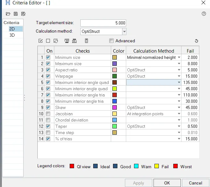
the given components have symmetry about their centre their fore components are meshed about half side and reflected on the other side.
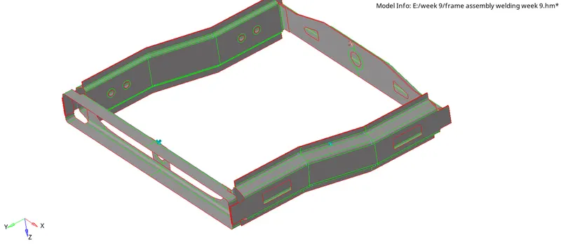
frame assembly welding
meshing is done with auto mid surface and the errors in fixed according to the criteria given above.
2D-auto mid surface- select surfaces to mesh-mesh type as mixed-element size to 5 units-mesh
reflected elements are connected with the equivalence option
after that qualitycheck is done on the 2d mesh.
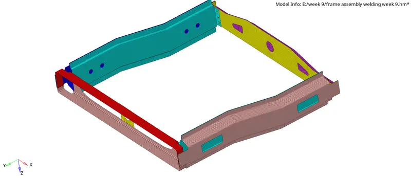
meshed model
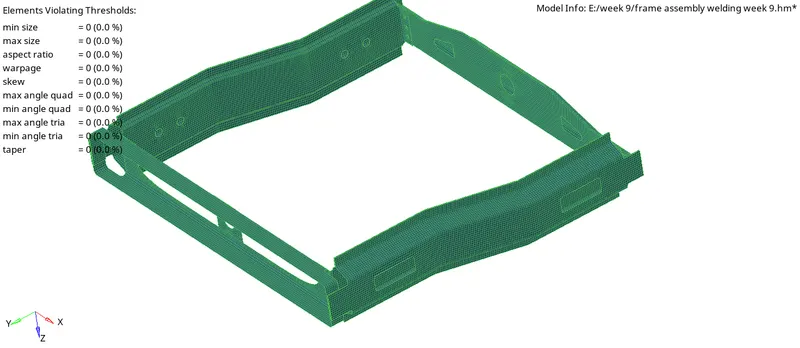
quality check
1D elements creation:
terminology:
connectors:
these are used to represent the connections between different geometric entities. hyper mesh offers different types of connectors in 1D,2D ,3D
like a bolt, area, spring, spot welds, adhesives, some rigid connectors and meant subtypes.
1. Right_Rail_2 & Front_truss_1:- Seam-Quad(angled+capped+L)
cad image:
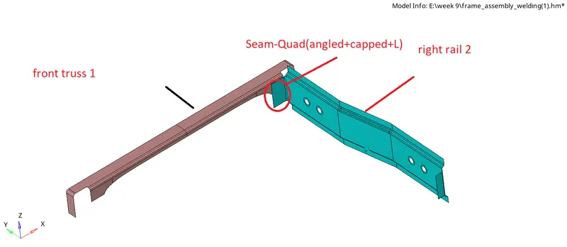
cad model of two components
to create the connector follow the below steps
1D-connectors-seam-set 'location' to the node path (we can go through lines also)in this we choose the position where we need to create the connectors-set spacing value to 5 units(which is equal to mesh size)-in 'connect what 'set it elements to connect and select the components between which the elements to connect-set 'tolerance' value not less than the gap between the components to connect-in 'type' select the option 'Seam-Quad(angled+capped+L)'- set run angle, cap angle, and run off angle if any(or change the values if connector not realized)-keep the option to quad transition and imprint (it elements of two components selected and also cause distortion of mesh which is need to adjust mesh manually)-create.

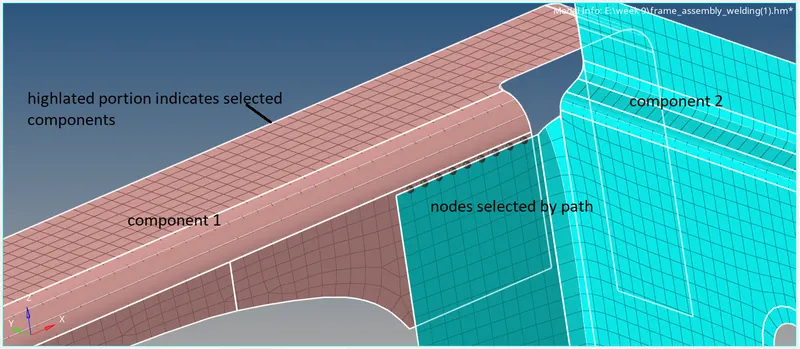
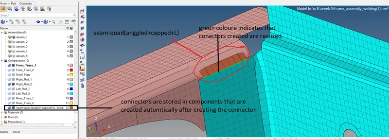
if the connectors are created properly then they are in green colour.
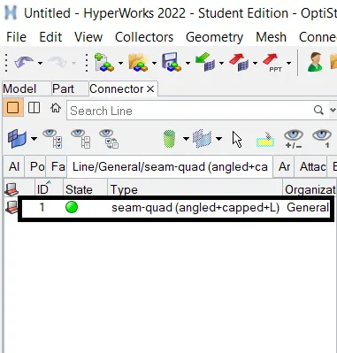
if it is in red in colour it means connectors are not realized if it is in yellow in colour.
quality check:
after the creation of connectors, we need to check for the quality of elements that should meet the above criteria. and also set mesh to flow properly
2D-quality index
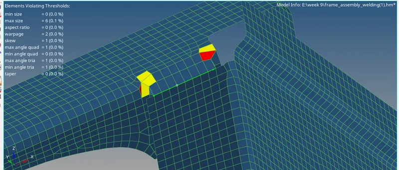

2D-quality index-QI settings
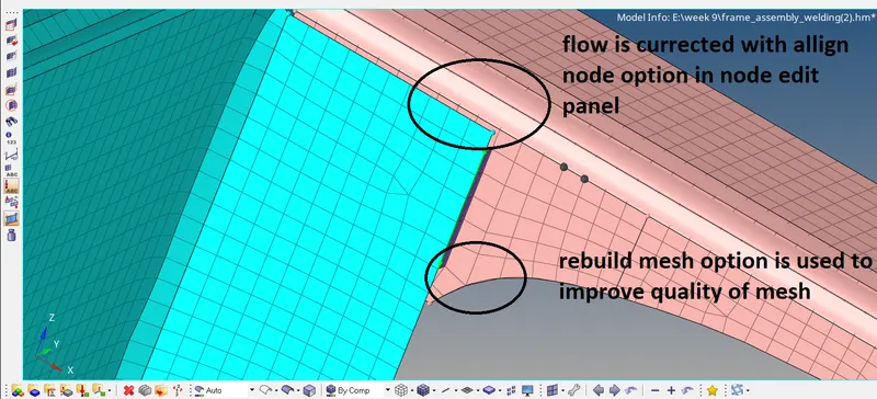
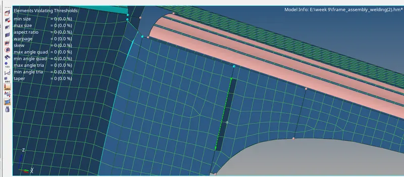
by using the above option we can improve the mesh quality.
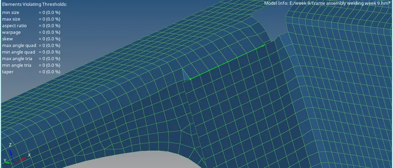
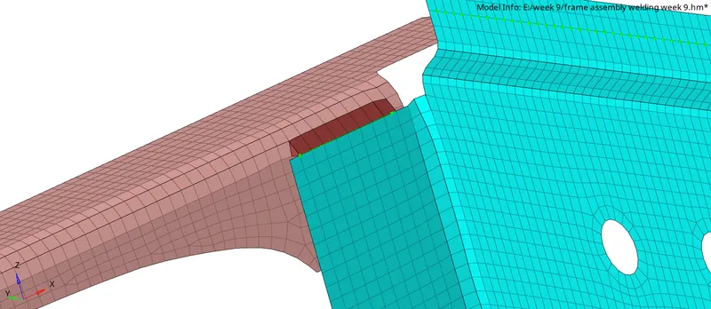
seam-quad(angled+capped+L)
2. Left_Rail_2 & Front_truss_1:- Quad elements
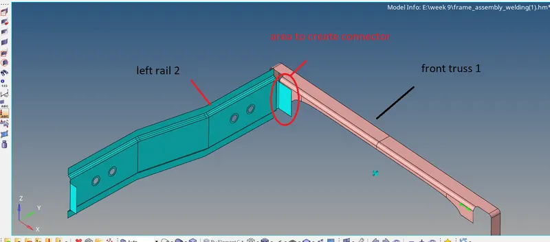
Left_Rail_2 & Front_truss_1
Like as above we can create a Connector for this joint only thing we need to do is by changing the type as quad
1D-connectors-seam-set parameters as an above-change type of connector as quad-create.
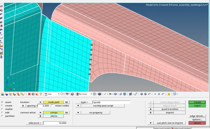
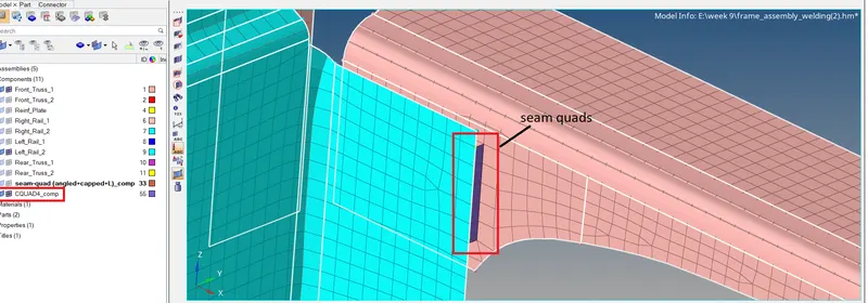
seam quads
We can check for connectors info at connectors browser
view-browser-hyper mesh-connectors
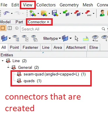
connector browser
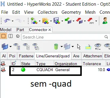
View-browser-hypermesh-connectors
In this browser, we can find different connectors created.
This green 🟢 indicates realized connectors (created successfully)
Red 🔴 indicates connectors which are not realized (due to error in creation)
But yellow 🟡 indicates connectors created need to be realized.
As of now, we are having all connectors realized
Quality check
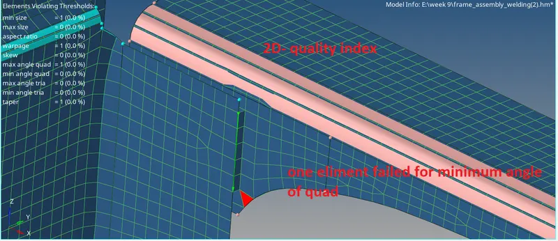
this can be cleared by cleanup tools present in the quality index panel and rebuilding the mesh.
sem-quad
3. Front_truss_2, Front_truss_1 & Right_Rail_1:- Spot weld with 2 Layers and 5 mm Diameter
seam weld is other than spot welding. seam welding is the joining of two flat surfaces of the same or dissimilar materials by using electrodes of roller-like shape here weld is done by rolling resistance there fore welding is done in the form of a line.
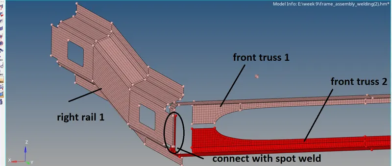
set the parameters as shown below

in this select nodes by the path by clicking right click on nodes option. in this we are given no of layers to sect is 2 but we need to connect 3 layers(components) therefore first we connect two then remaining to connect with its adjacent like how the first two are connected.
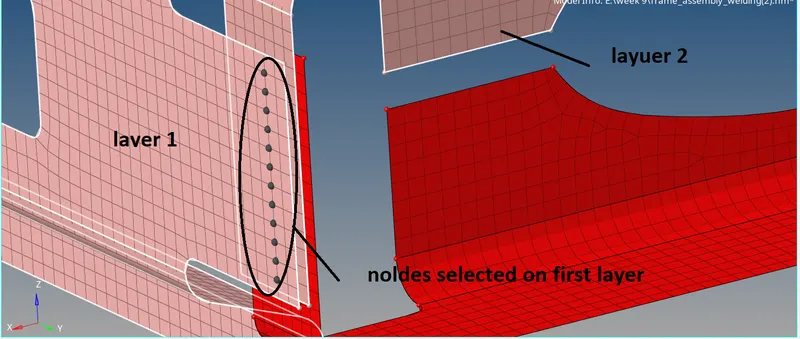
creating connectors between right rail-1 and front truss-1
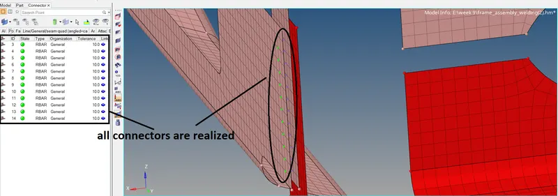
realized connectors
now we need to create a spot weld connector between front truss 1 and front truss 2 as similar as above
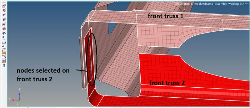
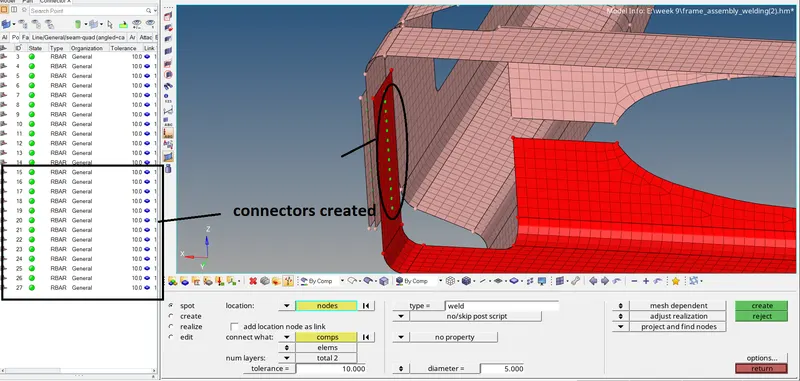
right rail 1,front truss 1 and front truss 2 spot weld with 2 temps and 5 mm dia
in this 1 d elements are created between nodes no need for a quality check
4. Front_truss_2, Front_truss_1 & Left_Rail_1:- Hexa (Adhesive)
adhesive: these are like having glue features and are widely used in the automobile industry to form a connection where the welding,fasteners and hemming connections are not possible.
geometries to connect with adhesive
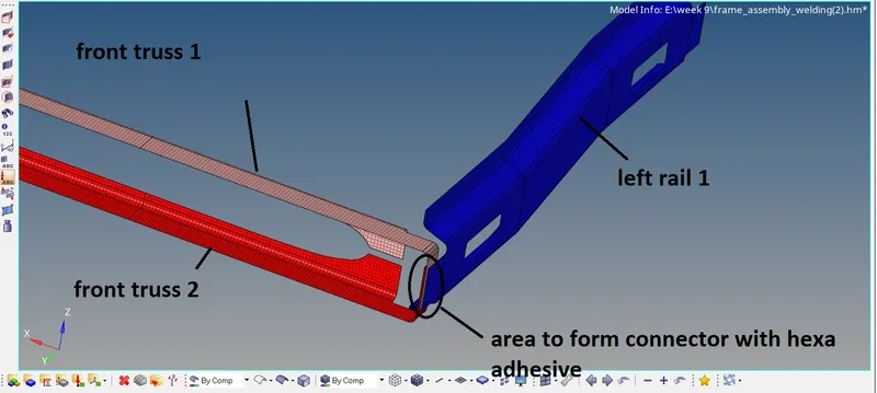
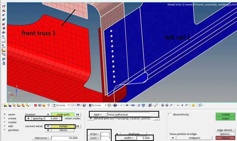
1D- CONNECTORS-SEAM-SET PARAMETERS VALUES AS ABOVE- SET TYPE OF CONNECTOR AS HEXA ADHESIVE- SELECT ANY COMPONENTS AS SHOWN-create
spacing:
we consider simply it as the edge dimension of Hexa and prefer to have equal mesh size.
strip:
it represents no of columns of Hexa that need to divide(or vertical division of Hexa)
coats:
it is opposite to strip.
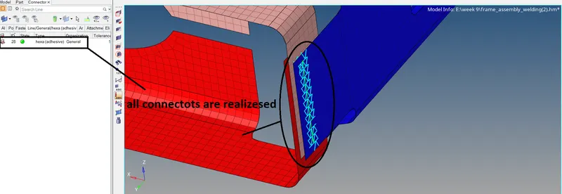
connectors created between front truss 1 and left rail 1
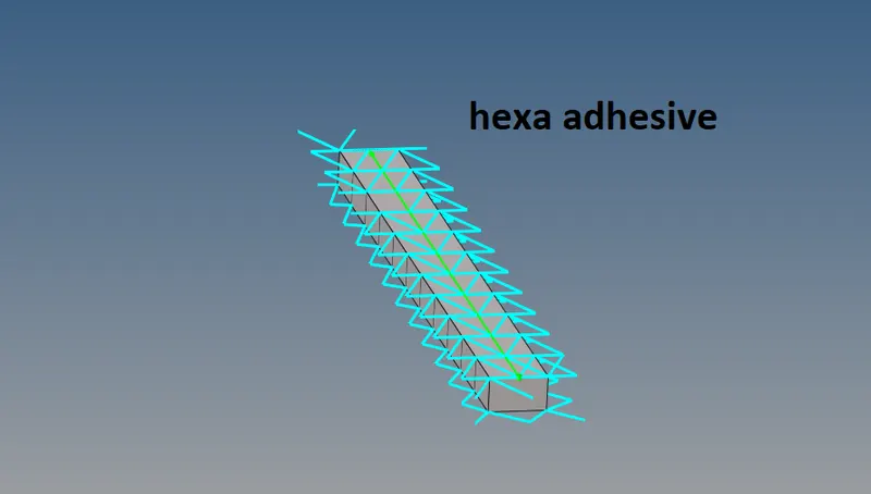
Hexa adhesive created
now create connectors between front truss 1 and front truss 2
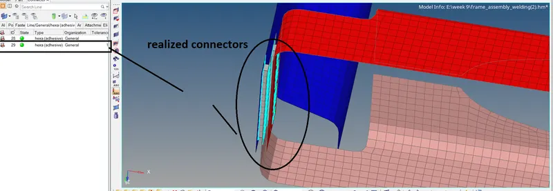
Hexa (adhesive) between front truss 1 and front truss 2
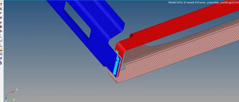
hexa adhesive between front truss 1 ,front truss 2 and left rail 1
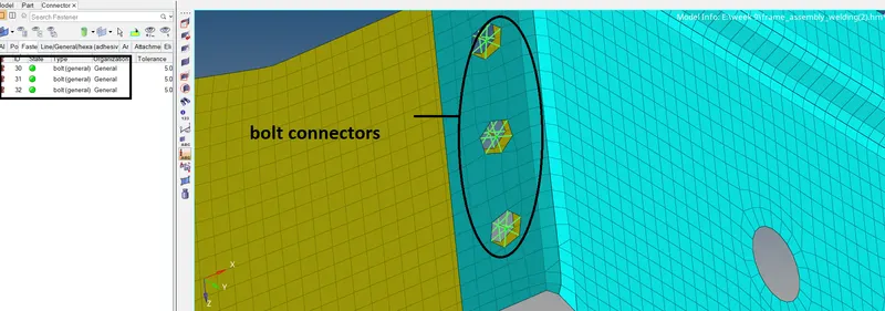
5. Rear_truss_2 & Right_Rail_2:- Bolt Connector
Bolted joints are one of the most common elements in construction and machine design. A connection between structural members is made with plates and bolts, as opposed to a riveted or welded construction. In HyperMesh, we use the RBE2 elements to represent the Bolt connection, since it has more stiffness.
cad model:
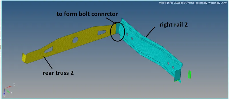
cad models
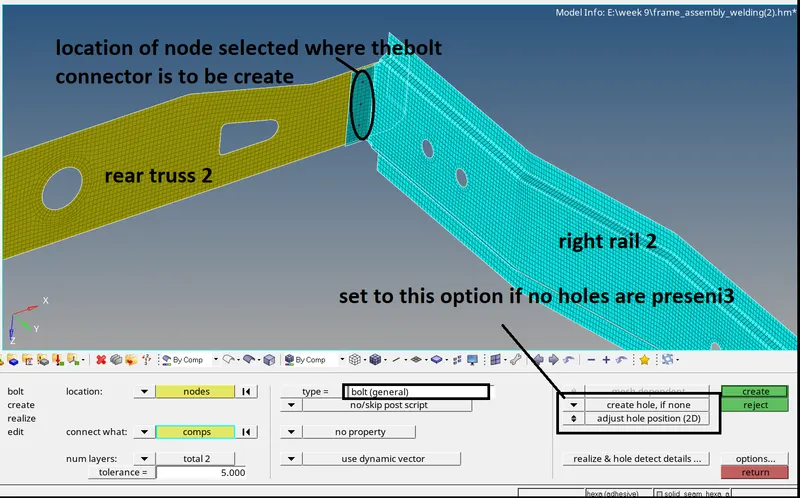
path to create bolt connectors
1D-CONNECTORS- bolt-select the location of connectors-select the components-select type of connector bolt(general)-as here no holes are present therefore set option to create a hole if not there
6. Rear_truss_2 & Left_Rail_2:- Bolt Connector
cad model:
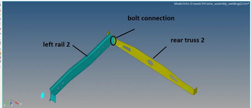
follow the same path given for 5th challenge to create a bolt connector for this also.
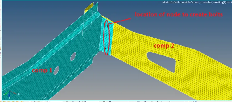
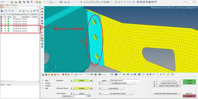
rear truss 2&left rail 2 bolt connection
7. Right_Rail_1 & Right_Rail_2:- Spot-weld with Rigid Elements
spot weld: Spot welding (also known as resistance spot welding) is a resistance welding process. This welding process is used primarily for welding two or more metal sheets together by applying pressure and heat from an electric current to the weld area.
cad model
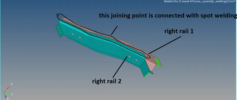
right rail1 and right rail2
1D -spot weld-choose using nodes-as the long edge to connect select nodes -nodes option which allows to select multiple of independent nodes at a time and then in the same sequence need to select dependent nodes-choose element cong to rigid-enter search tolerance more than the gap between the components supposed to connect -create.
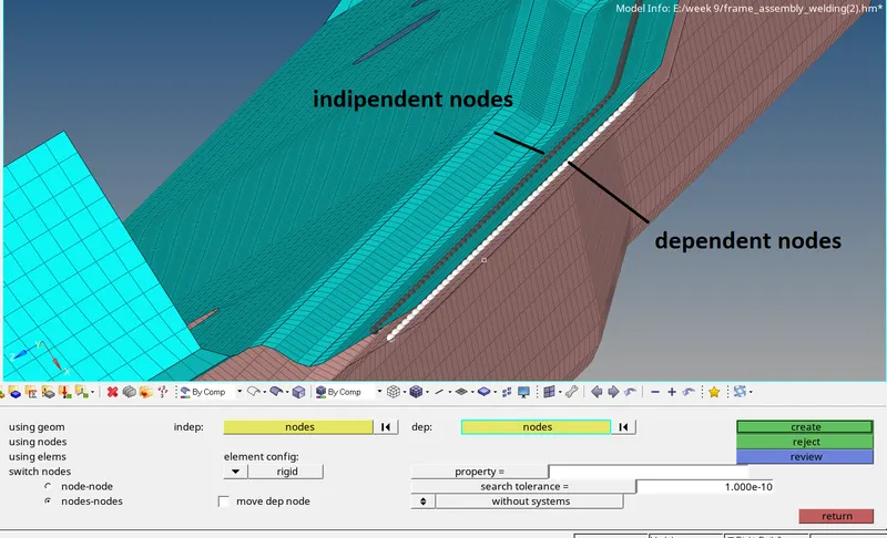
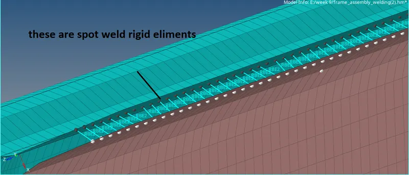
spot weld with rigid elements
connect on the second side as same as done on the first side
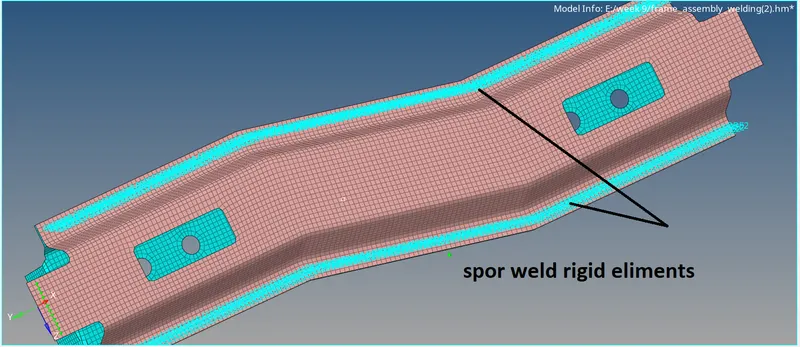
8. Left_Rail_1 & Left_Rail_2:- Spot-weld with Spring Elements
creating spot weld with spring elements will create the connection between the components with RBE3 elements.
cad model:
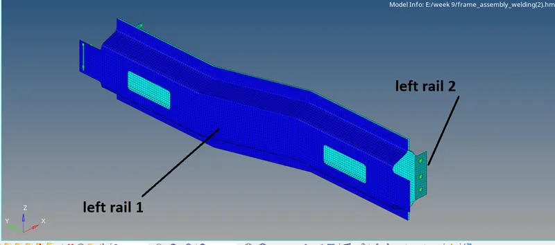
left rail 1&left rail 2 cad model
1D-spot weld-follow all the settings as above but change the element type to spring-create.
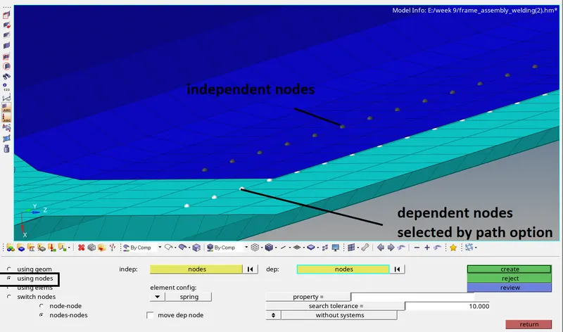
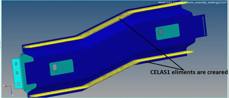
spot weld with spring elements
9. Rest all the component left Join them with suitable connectors:
spot weld with rigid eliments
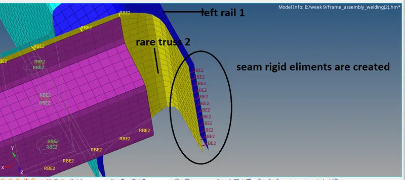
1.heare we are left with some of places to connect those are
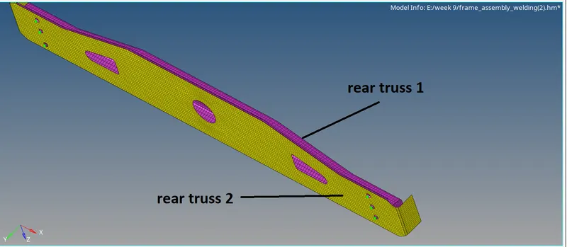
rear truss 1&rear truss 2
as rear truss 2 is connected with fasteners then i would prefer to connect these two components with spot weld rigid eliments.
1D-spot weld-using nodes-select dependent and independent nodes respectively and select elementconfg as rigid
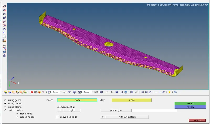
second side
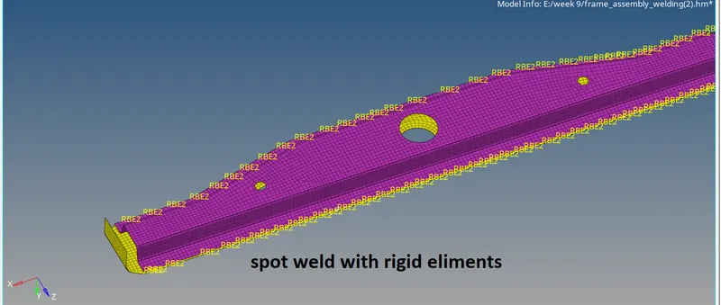
result
2. adhesive contact
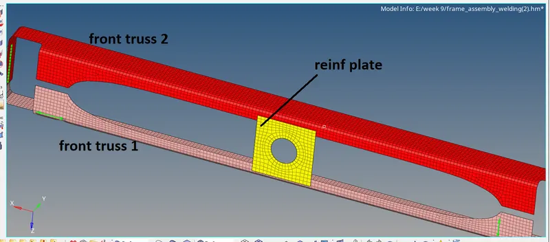
to create the connector between front truss 1, front truss 2 and reinf plate with adhesive-contact
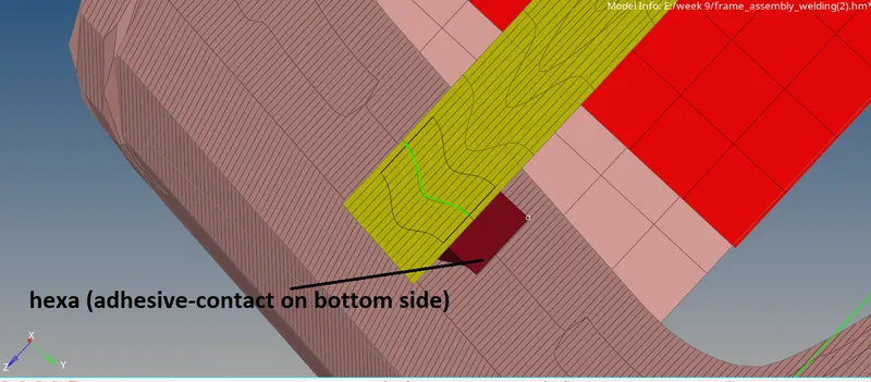
1D-connectors-seam-select the nodes by path -select the components to connect-change connector type as Hexa (adhesive-contact)-set strips coast-set width as equal to mesh size other vice meshes get distorted-create.
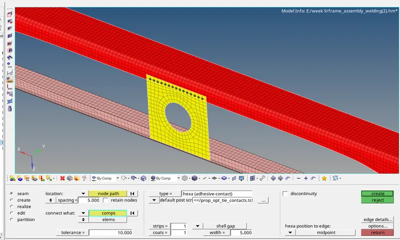
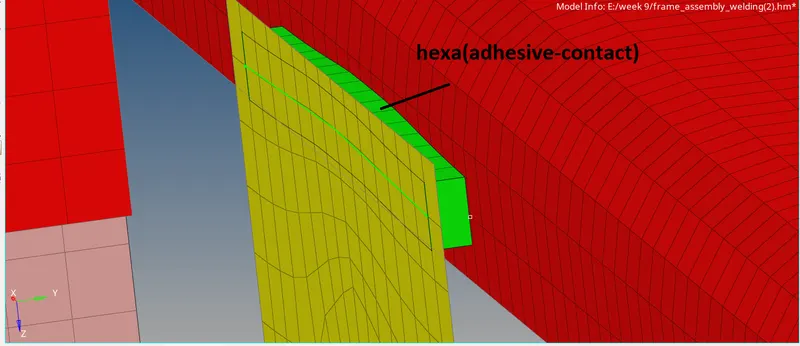
Hexa (adhesive -contact created) on upper side
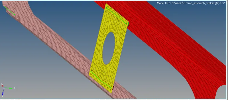
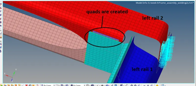
similarly, create the same contact on the bottom side
conclusion :
connectors are deals with FE components.
if any unrealized connectors are found then follow the below procedure
view-browser-hyper mesh-connectors -in this go to the connectors that are unrealized-click on them(details of the connector are visible only when we should return to out of connectors panel -then in properties of connectors check the reverse option modify it and try to realize by right-clicking on the connector and select realize option)
how to delete connectors
it can be deleted directly by deleting components itself
if not found in components or wanted to delete individual then go to connectors browser as mentioned above and go to connector need to delete right click on it -then choose to delete option and then select connectors with FE created]
check for the mesh quality after the connectors created,