Week 4-1D Element Creation Challenge
aim:-
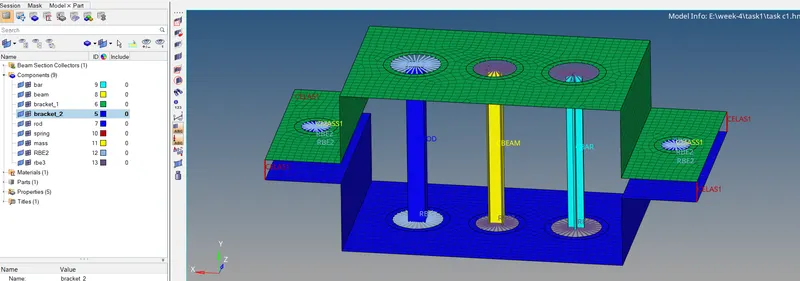
to create the mesh and 1D elements with given specifications on the given component as shown below
fig 1
task 1:-
objective: the creation of mesh
procedure :
* load the ".IGES" file into the hyper works.
file->import->geometry->set fie type as IGES->load the location of fie ->select the fie->import.
* as the imported component in 3D has symmetrical thickness throughout the body, we can obtain the mid surface of the component and perform 2D meshing with shell elements, reducing the analysis and computational timings.
* creation of mid surface
Geom->mid surface->select auto mesh option->select extraction options->select type as skin offset->return to auto extraction->select selection option as surfaces->select the surfaces->extract.
* create a mid surface of each bracket as different components.
** in this while creating a mid surface we are facing problems with fillets which are not in the proper way with other extraction options other than skin offset.
*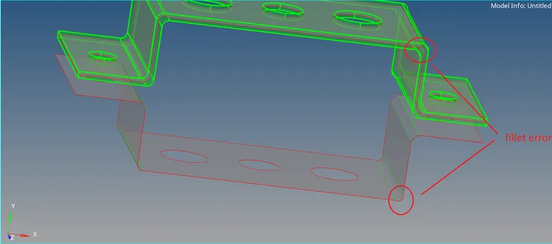
fig 2
*above error is overcome with the skin offset option.
* after extraction of mid surface go for a topological cleanup
and set the geometry to BY Topo mode so that we can visualize the connectivity of all edges.in this model, all edges are in perfect connections
*creation of mesh
2D->auto mesh->set selection option to surfaces->set element size to 5 units->element type to quads->set mesh in interactive(so that we can edit number of nodes)->mesh
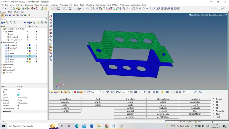
2. TASK 2 fig 3
CREATION OF 1D ELEMENTS
1D elements are having one dimension more than the other two dimensions. these are formed between two nodes.
a) ROD ELEMENT:-
rod is a rigid element and can take compressive and tensile loads. usually in a circular cross-section.
rigid elements are those having infinite stiffness(i.e., which will not bend and move when the load is applied)
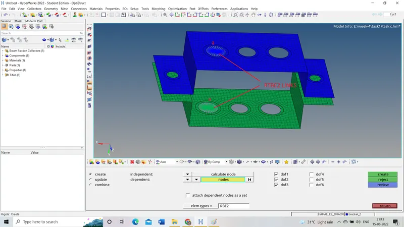
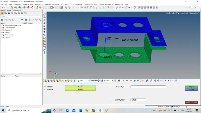
in this instance, we need to create rod elements using RBE2 (rigid links) at the position 'a' as shown in above fig1
step 1:-
creation of RBE2 links on brackets 1 and 2
1D->rigids->change dependent nodes as 'multiple nodes' ->change the independent node as 'calculate node' ->select the nodes at the edges of the hole as 'multiple nodes'->set element type 'RBE2'->uncheck dof 4,5 and 6(allowing for rotational degrees of freedom)->create.
step 2:-
creation of rod element between two nodes formed by RBE2 links on that two brackets.
1D->rod->set in create mode->select the node 1 and 2->change element type from CWELD to CROD ->create.
step 3:-
creation of hyper beam element of box shape with given specifications.
1D->hyper beam->select to 'standard section' ( or generative)->change to hyper beam(or optistuct)->select cross-section as 'THINWALLED BOX'->create (it will open a hyper beam window)->change the default dimensions with given dimensions in 'parametric definition box'.
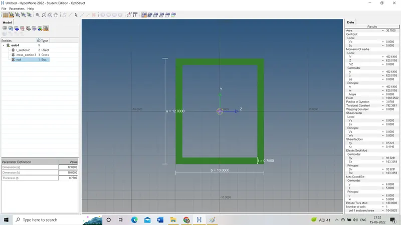
* to return to the model window activate the model icon in the menu bar.
step 4:-
create property 'rod'
* open model in tab area (where components and their properties include)
right-click in tab tab area->create->property.
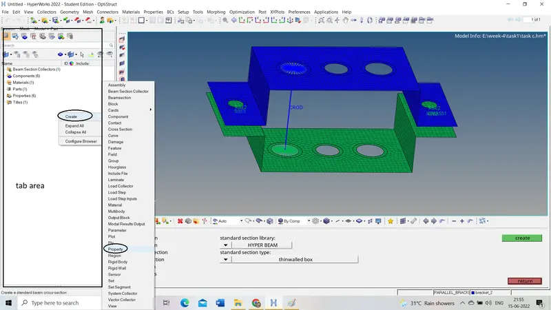
* rename the property as rod (for simplicity).
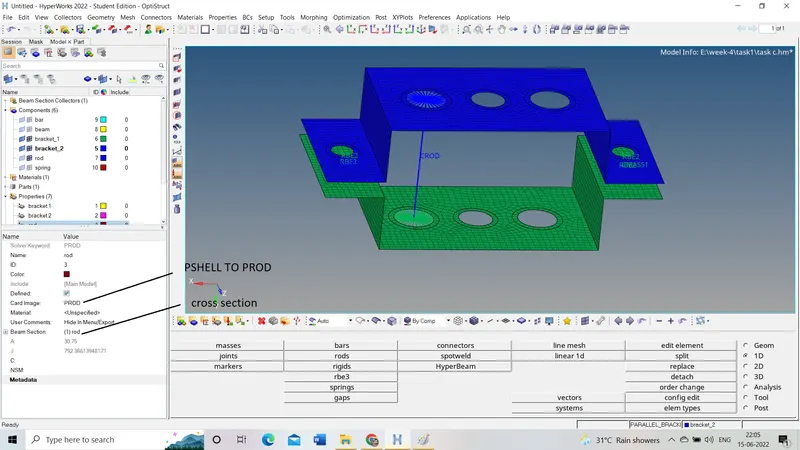
open property(named as a rod)->change card image from PSHELL to PROD->select beam section(as box created in the hyper beam).
step 5:-
assigning the created hyper beam to the 1D ROD element.
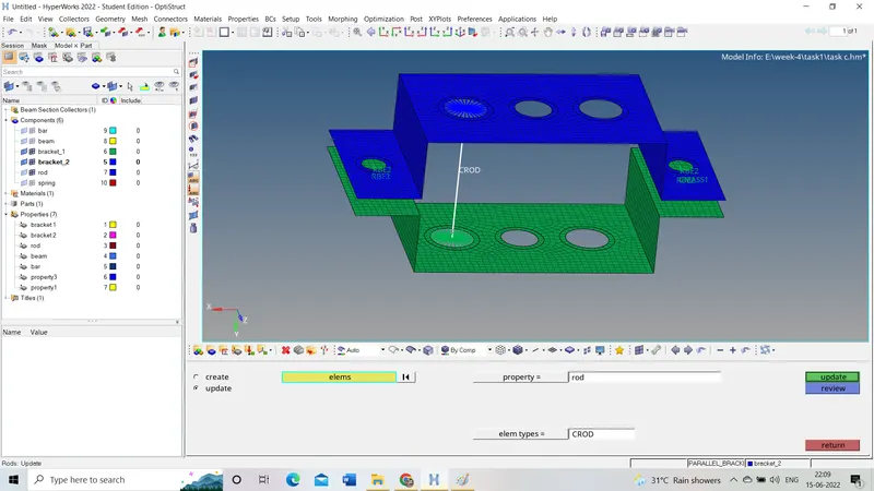
1D->rods->change from create to update->select he element to update->select the property to assign ( 'rod')->change element type to CROD->update.
step 6:-
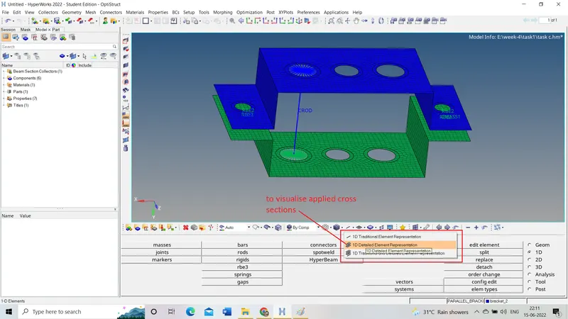
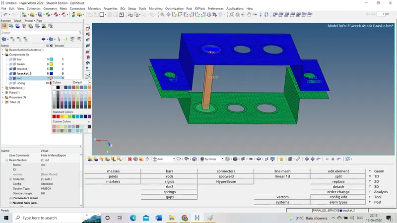
to visualize the cross-section assigned to the element change '1D TRADITIONAL REPRESENTATION' TO '1D DETAILED REPRESENTATION'. in the menu bar
result:-
B) BEAM ELEMENT:-
beam elements can be subjected to bending along with tensile and compressive loads. these are any type of cross-sections with symmetricity.
RBE3 elements are not like RBE2 elements. these can move front, back, up, and down.
step 1:-
creation of RBE3 links
1D->rbe3->set the first node to calculate nodes in selection options and the second node to multiple nodes->then select the multiple nodes on the edges of hole B ->create
step 2:-
creation of BEAM element
1D->bars->select nodes->change element type as CBEAM->create.
step 3:-
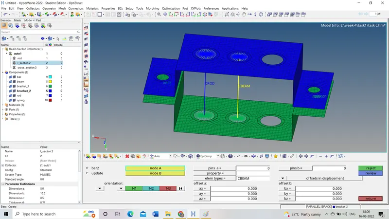
creation of I section
hyper beam->generic sections->create->right click on tab area-> following fig shows the next steps to follow for the creation of any type of section (for instance consider I section)
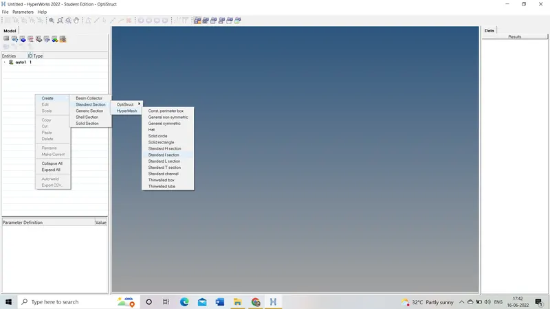
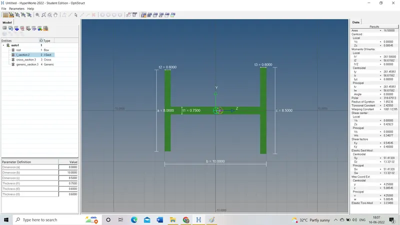
* give the required dimensions in the parametric definition box to create a specific I section.
* after the creation of the section return to model space which will exit from hyper beam application.
step 4:-
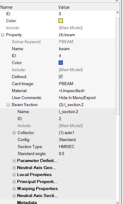
create a property for beam-like property created for the rod only change card image from PSHELL TO PBHEAM and assign beam section as created Isection.
step 5:-
assign the property to the beam component
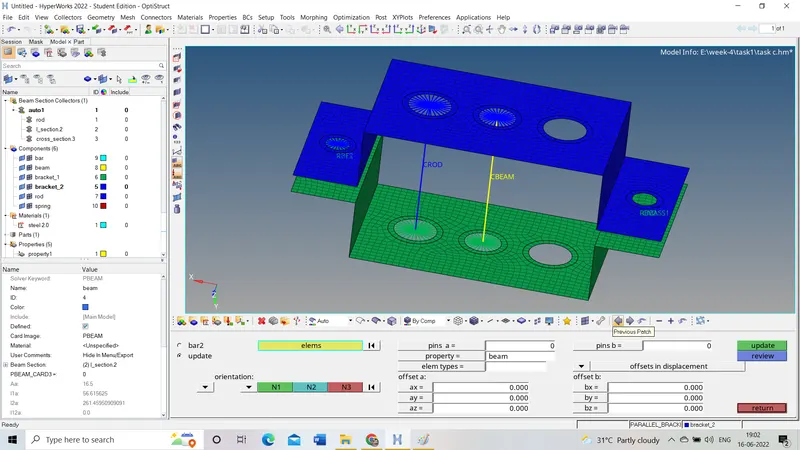
1D->bar->update->select element(CBEAM)->select property (beam)->select three nodes for reference->update .
step6:-
to visualize the cross-section assigned to the cbeam element change 1D translational element representation to 1D detailed element representation.
result:-
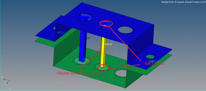
C) BAR ELEMENT
The BAR element is the same as the beam element. on the bar element, we can apply bending, tensile, and compressive loads.
the bar is generally of a circular cross-section.
but for this instance, we create X type of section and assign it to the bar element.
step 1:-
creation of RBE3 LINKS
follows the same steps as mentioned in the beam element for the creation of RBE3 elements.
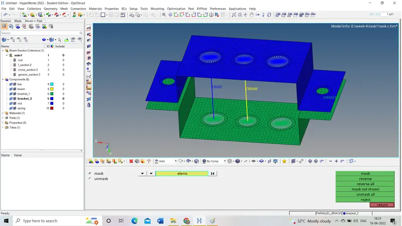
step 2:-
creation of CBAR ELEMENT
same as beam element but change element type as CBAR
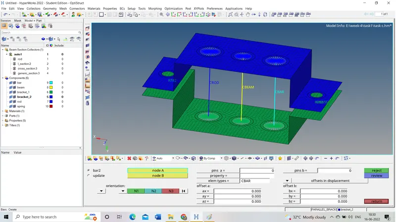
step3:-
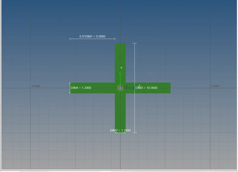
creation of X (cross) section
1D->hyper beam->generic section->create->right click on tab area->below figure shows the remaining steps more clearly.
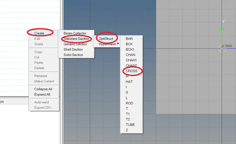
* give the dimensions to create the section with specific dimensions as follows
step 4:-
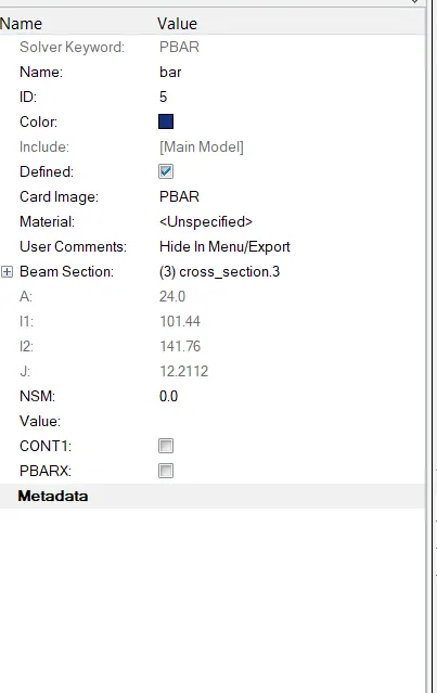
creation of property for bar element .it is also same as previous rod and beam
the only change is the card image from PSHELL TO PBAR and assigns created cross-section to beam section as shown below.
step 5:-
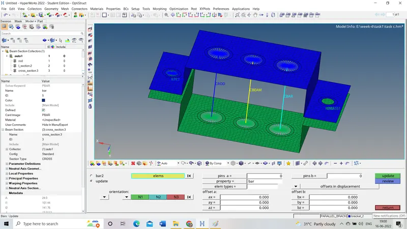
assign the property to the component (bar element)
it is the same as a beam but select property as the bar.
step 6:-
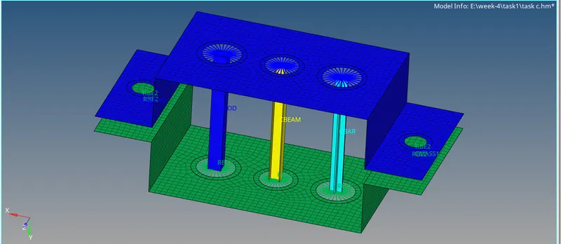
to visualize the cross-section assigned to the cbeam element change 1D translational element representation to 1D detailed element representation.
d&e) to create mass at positions as shown in question
masses in hyper mesh masses can be applied on nodes
step 1:-
creation of RBE2 LINKS
1D->rigids->change dependent nodes as 'multiple nodes' ->change the independent node as 'calculate node' ->select the nodes at the edges of the hole as 'multiple nodes'->set element type 'RBE2'->create.
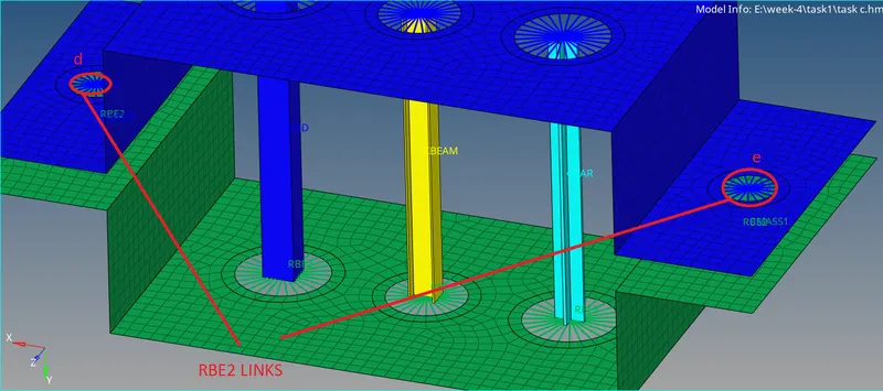
step 2
location of mass of magnitude 10
1D->select nodes at d and e created by RBE2 links->enter mass magnitude->select element type as CMASS1->create
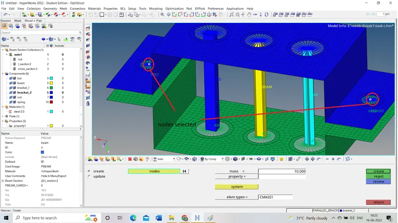
* We can create a component of mass and assign it to it to maintain its property individually.
f) joining of two components with the spring element
step 1:-
create a component of spring
as shown in figure
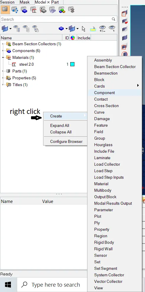
* We can create the property and assign property to the component.
*make spring component a current component
step 2:-
creation of spring element
1D->springs->select nodes 1&2->set element type as CELAS1->create.
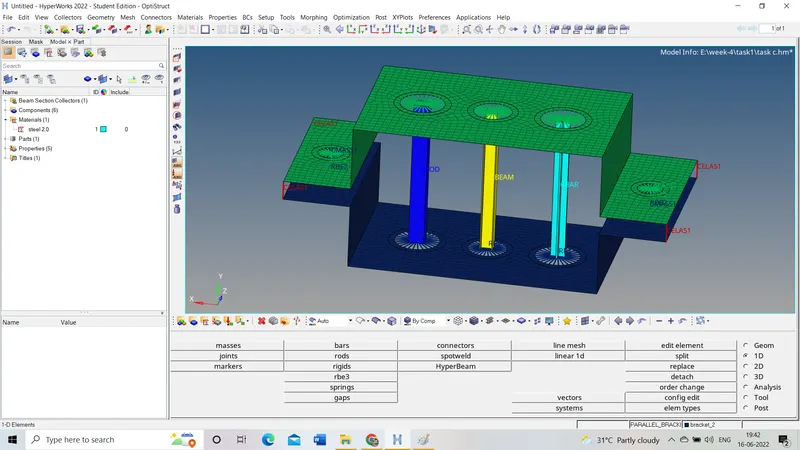
total result:-
each element type is represented with different colors for ease of identification