Week 9-Creation of 1D Connectors Challenge
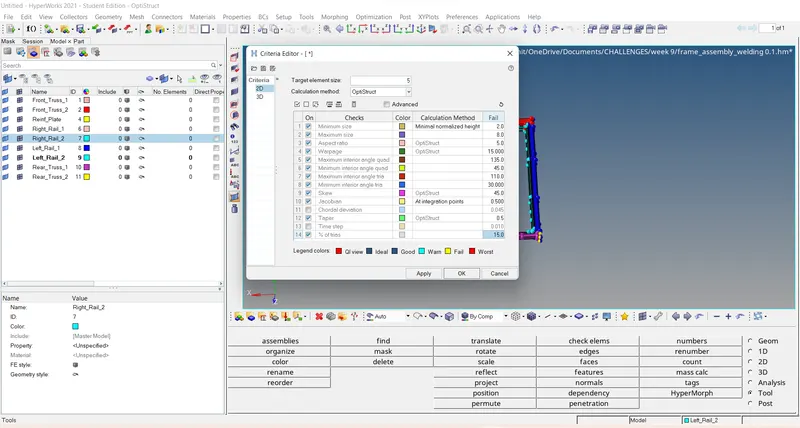
Aim :- Mesh the given geometry. Provided below are the quality parameters that you have to follow.
Target Element size - 5 Units
|
S.N |
Quality Criteria |
Value |
|
1 |
Aspect Ratio |
5 |
|
2 |
Skewness |
45 |
|
3 |
Warping |
15 |
|
4 |
Taper |
0.5 |
|
5 |
Min. Length |
2 Units |
|
6 |
Max. Length |
8 Units |
|
7 |
Min angle Quad |
45 |
|
8 |
Max angle Quad |
135 |
|
9 |
Min angle Tria |
30 |
|
10 |
Max angle Tria |
110 |
|
10 |
Tria % |
15 |
Create connector and Attach the various parts of the given model
1. Right_Rail_2 & Front_truss_1:- Seam-Quad(angled+capped+L)
2. Left_Rail_2 & Front_truss_1:- Quad elements
3. Front_truss_2, Front_truss_1 & Right_Rail_1:- Spot weld with 2 Layers and 5 mm Diameter
4. Front_truss_2, Front_truss_1 & Left_Rail_1:- Hexa (Adhesive)
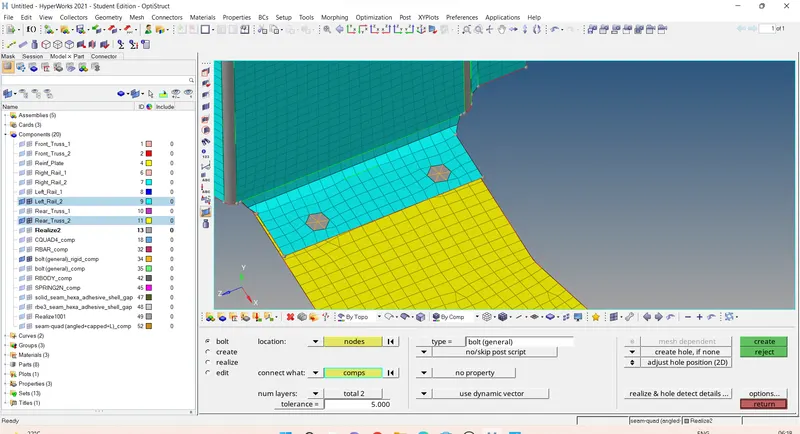
5. Rear_truss_2 & Right_Rail_2:- Bolt Connector
6. Rear_truss_2 & Left_Rail_2:- Bolt Connector
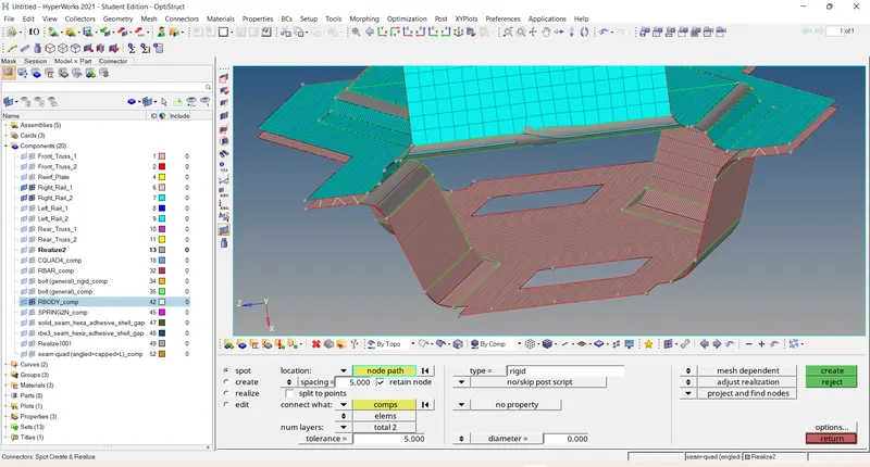
7. Right_Rail_1 & Right_Rail_2:- Spot-weld with Rigid Elements
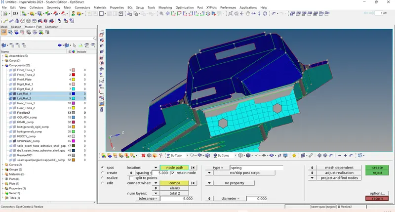
8. Left_Rail_1 & Left_Rail_2:- Spot-weld with Spring Elements
9. Rest all the component left Join them with suitable connectors
Procedure :-
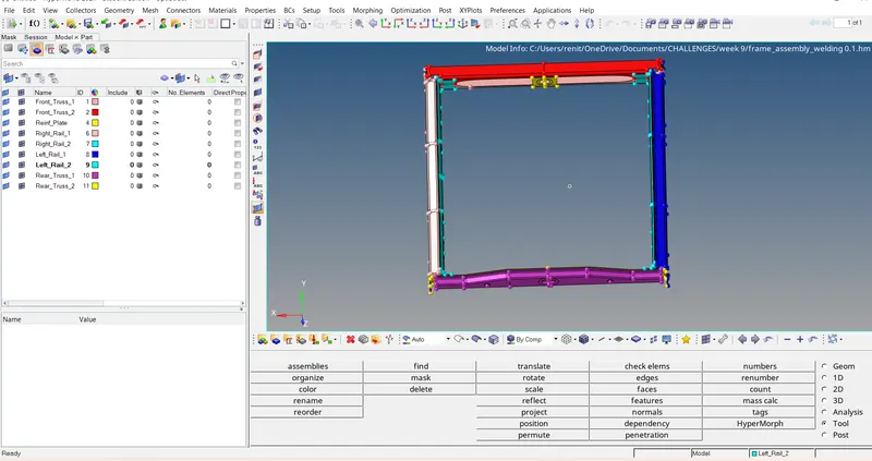
Step 1 :- import the model
file-open-model-select the model-open
Step 2 :- Applying the quality criteria.
Preferences - criteria file settings - give the quality parameters- apply -ok.
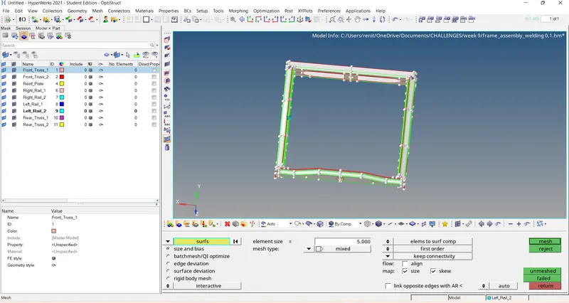
Step 3 :- Generate mesh to the given model.
2D -auotmesh-surface-displayed-element size 5 - element type - mixed - mesh.
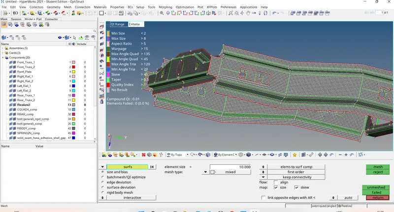
Step 3 :- Checking the quality criteria and improving the mesh flow.
Step 4 :- Assigning the property amd material.
Assigning material and property to all the components.
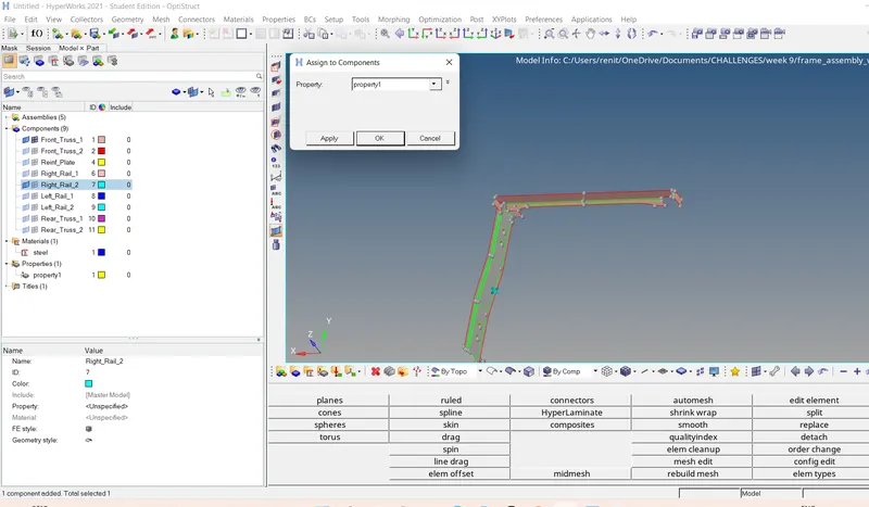
Property assigned.
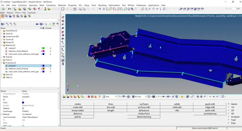
Material assigned.
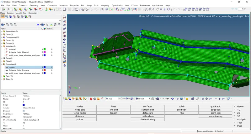
Step 5 :- Creating connectors.
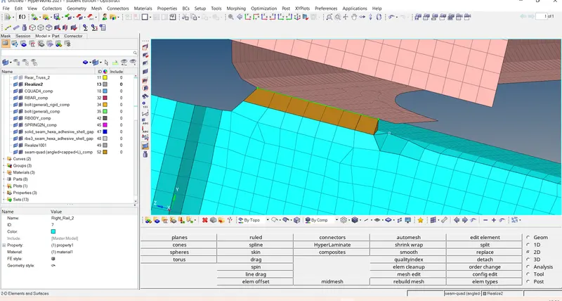
1. Right_Rail_2 & Front_truss_1:- Seam-Quad(angled+capped+L)
2D - Connectors - seam - location -node by path - select the nodes - spacing=5 - turn on retained node -tolerance = 5 - select the components - type= Seam-Quad(angled+capped+L) - no property - create.
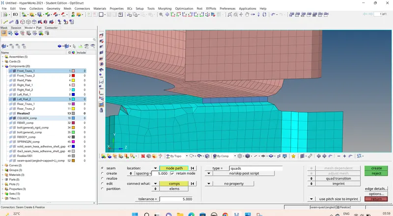
2. Left_Rail_2 & Front_truss_1:- Quad elements
2D - Connectors - seam - location -node by path - select the nodes - spacing=5 -tolerance = 5 - select the components -type - quads -create.
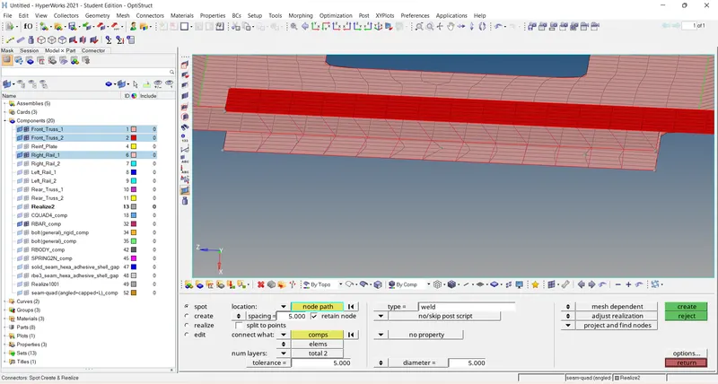
3. Front_truss_2, Front_truss_1 & Right_Rail_1:- Spot weld with 2 Layers and 5 mm Diameter
2D - Connectors - spot - location - node by path - spacing =5 - retained node -select 1st and 2nd component - tolerance 5 -type -weld - diameter = 5 - create.
2D - Connectors - spot - location - node by path - spacing =5- retained node -select 2nd and 3rd component - tolerance 5 -type -weld - diameter = 5 - create.
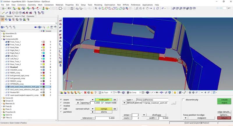
4. Front_truss_2, Front_truss_1 & Left_Rail_1:- Hexa (Adhesive)
2D - Connectors - seam - location -node by path - select the nodes - spacing=5 -tolerance = 5 - select the components 1st and 2nd -type -hexa(adhesive)- stroips=2 -coats = 2 - width = 5 - create.
2D - Connectors - seam - location -node by path - select the nodes - spacing=5 -tolerance = 5 - select the components 2nd and 3rd -type -hexa(adhesive)- stroips=2 -coats = 2 - width = 5 - create.
5. Rear_truss_2 & Right_Rail_2:- Bolt Connector
2D -connectors -bolt - location =node -selelct 1 node - selct two components - tolerance = 5 - type =bolt general - no property - create hole if none -adjust hole postion - create .
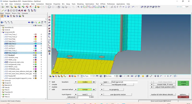
6. Rear_truss_2 & Left_Rail_2:- Bolt Connector.
2D -connectors -bolt - location =node -selelct 1 node - selct two components - tolerance = 5 - type =bolt general - no property - create hole if none -adjust hole postion - create .
7. Right_Rail_1 & Right_Rail_2:- Spot-weld with Rigid Elements.
2D - Connectors - spot - location - node by path - spaceing =5 - retained node -select 1st and 2nd component - tolerance 5 -type - - rigid -create.
8. Left_Rail_1 & Left_Rail_2:- Spot-weld with Spring Elements.
2D - Connectors - spot - location - node by path - spaceing =5 - retained node -select 1st and 2nd component - tolerance 5 -type - - spring -create.
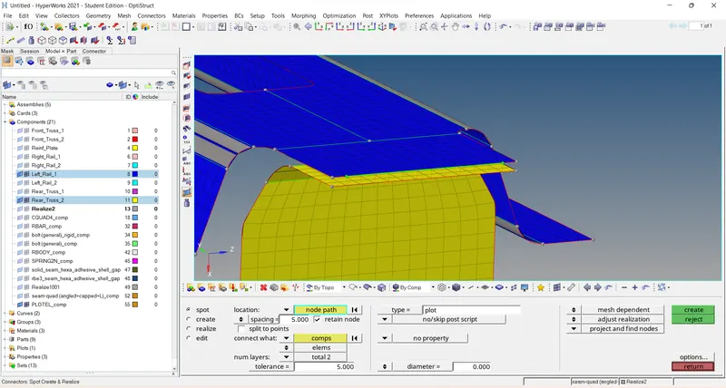
9.Left_Rail_1 & rear trusss_2 :-spot - plot connectors.
2D - Connectors - spot - location - node by path - spaceing =5 - retained node -select 1st and 2nd component - tolerance 5 -type - plot -create.
10 . front truss 2 & right rail 2 :- Rod elements.
2D - Connectors - seam - location -node by path - select the nodes - spacing=5 -tolerance = 5 - select the components - type rod - - create.
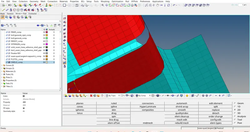
Final model :-
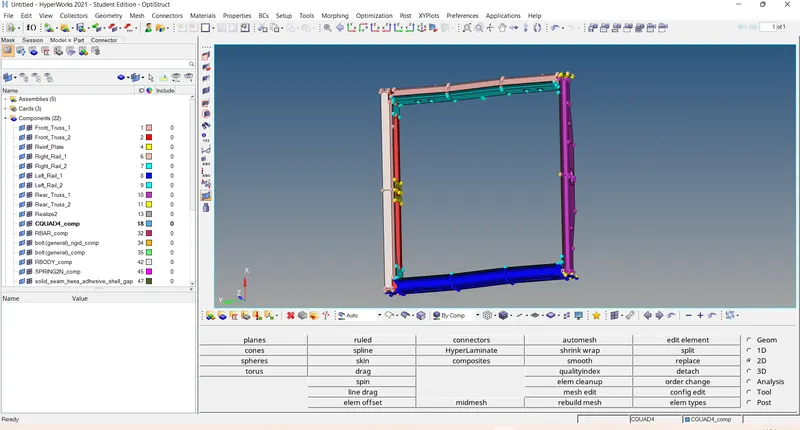
Result :-Meshed the given geometry. Provided the given quality parameters and Create connector and Attach the various parts of the given model .
Learned outcomes :-
*study about the different connectors.
*study about what are the errorsmand how to realise it.
*Got a knwledgeof the connectors toolls amd improve the mesh quality.
thanks
Renith Balachandran M