Week 6-Meshing of Hood Challenge
AIM : Mesh the component given below and assign thickness
Target Element Length = 5 Units
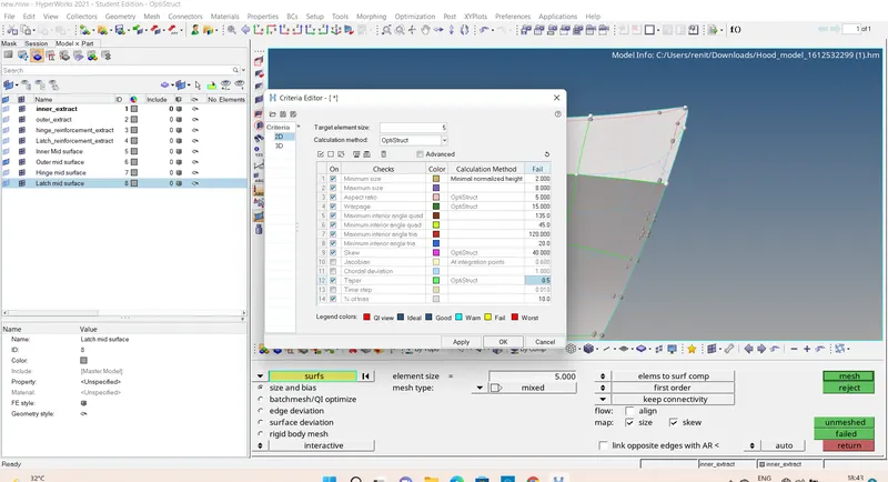
| S.N | Quality Criteria | Value |
| 1 | Aspect Ratio | 5 |
| 2 | Skewness | 45 |
| 3 | Warping | 15 |
| 4 | Taper | 0.5 |
| 5 | Min. Length | 2 Units |
| 6 | Max. Length | 8 Units |
| 7 | Min angle Quad | 45 |
| 8 | Max angle Quad | 135 |
| 9 | Min angle Tria | 20 |
| 10 | Max angle Tria | 120 |
| 10 | Tria % | 10 |
Procedure :
Step 1: Import the model
File - open - model - selelct the model - Open
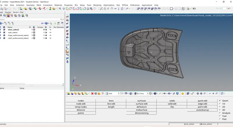
- Delelte the solid part- Delelt - SURFACE - Select the surface - attached - delelt entitiy.
Step 2: Taking Mid surface separately for each component
Creating Mid surface of inner surface
- Turn on inner surface and turn off other components .
- Geomerty - mid surface - extraction options (offset+sweeps +plane ) - auto extraction - select the inner surface- attached - extract.
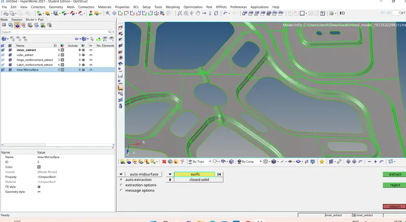
- Rename the mid surface as inner mid surface .
Creating outer Mid surace .
- Turn on outer surface and turn off other components .
- Geomerty - mid surface - extraction options (offset+sweeps +plane ) - auto extraction - select the outer surface- attached - extract.
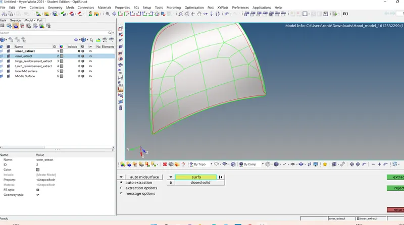
- Rename as outer mid surface.
Creating Hinge Mid surace .
- Turn on Hinge surface and turn off other components .
- Geomerty - mid surface - extraction options (offset+sweeps +plane ) - auto extraction - select the Hinge surface- attached - extract.
- Rename as hinge mid surface.
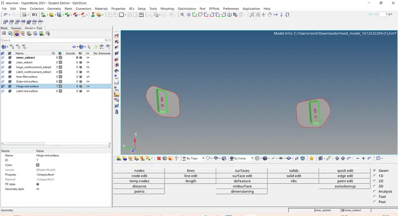
Creating Latch Mid surace .
- Turn on latch surface and turn off other components .
- Geomerty - mid surface - extraction options (offset+sweeps +plane ) - auto extraction - select the latch surface- attached - extract.
- Rename as latch mid surface.
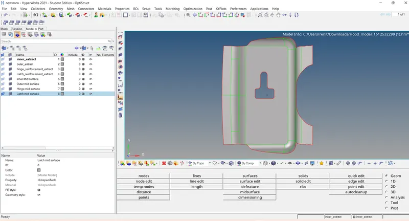
Step 3 : Giving Quality Criteria as given.
Preference - Criteria file settings - Traget element size 5 and give the mentioned quality criteria - Apply - Ok .
Step 4 : Geometry clean up.
Toggle : Toggle the unwanted cuts .
Geomerty - Quick edit - Toggle - Selelct the line and toggle it .
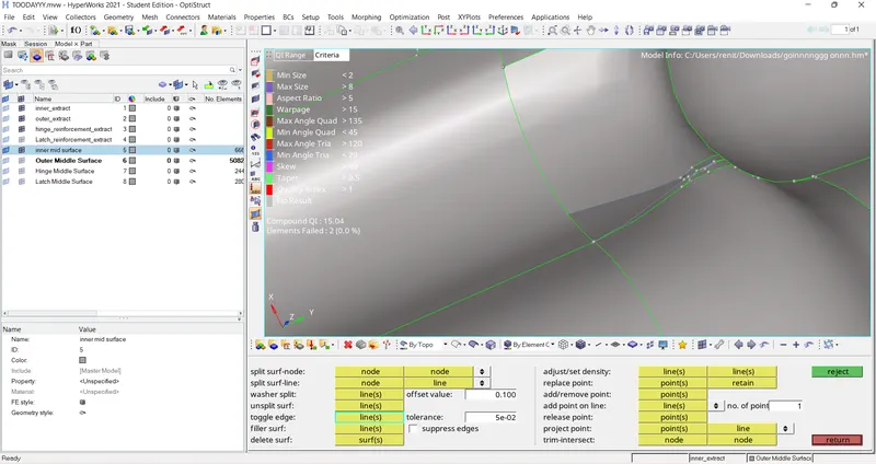
Adding Lines : If lines is nned to cut the surface.
Create a points and join together by
Geometry - quick edit - Node to Node / Node to line - Create lines.
Removing unwanted points : Geometry - Quick edit- add/remove points - Drag the right click mouse to remove points.
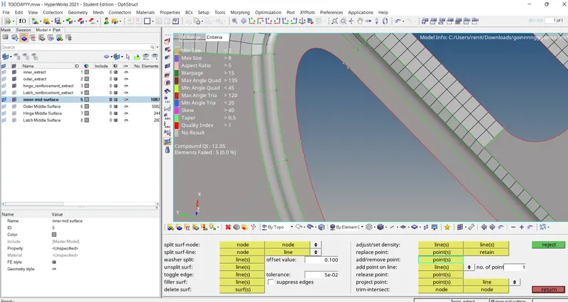
Step 5: Meshing the given copmonents part by part.
Meshing Outer Surface.
Before doing meshing we need to seperate part by part ,if any unwanted line is there we nened to remove.
- To remove the cuts : 1D - Quick edit -toggle edge - Click the line which is no need there or toggle it.
- Makes a part as better can do.
- Then Mesh the component : 2D - auto mesh - Surface - elelment type (Mixed)- element size =5 units - Selelct the surface oif one part - mesh .
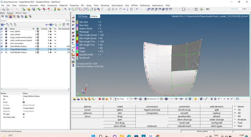
- Geomerty colour mode into By Topo
- Element color mode into By Element quality.
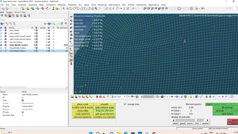
Removing TRIAS :
Dragging the trias ;
2D - Quality Index - Clean up tools - Drag tria element - drag the tria and drag to the need Area .
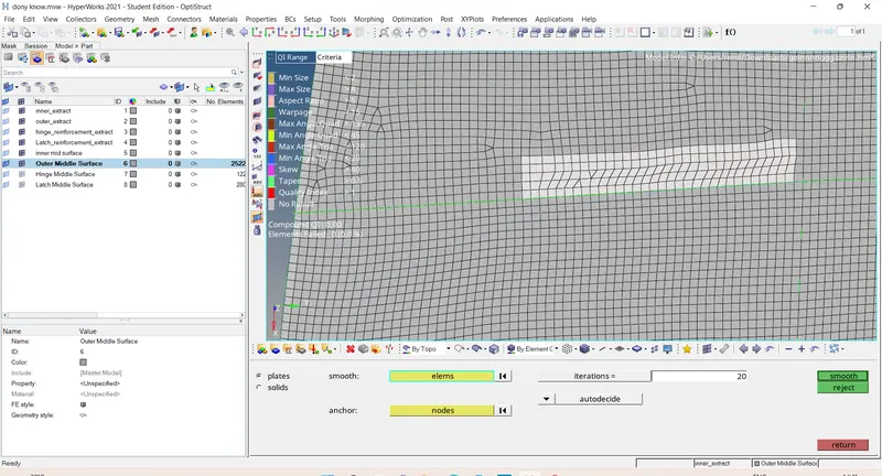
Opposite Trias :
If oposite trais is there we can join together and to make a line to doing better mesh flow.
Drag the trais to the near to the opposite tria ;
2D - Auto mesh - Make as element - select the elelmts which are connected to the opposite trias and makes as square selelction - mesh .
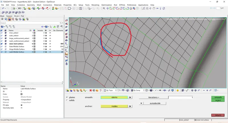
Avoid the trias falling on featured line :
Swapping the edge :
2D - Quality index - clean up tools - swape the edge - click the line which is faling on featured line .
Smothning: 2D - Smooth - Selelct the element want to smmoth - smooth
Rebuild mesh :
- IF mesh is not good the Rebuild the mesh : 2D - Rebuild mesh - elelment - selelct the all elelmnt which was meshed and rebuld the mesh to get better mesh.
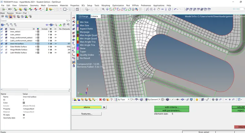
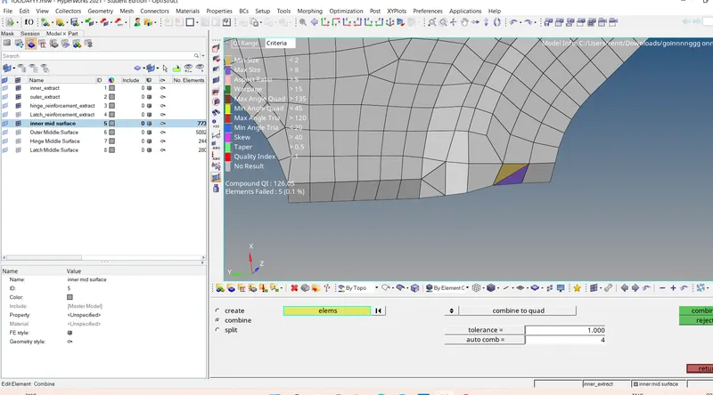
Combine Elements : if two tria are attached ,we can combinew each other by ,
2D - Element Edit - combine - select to tria attached - Combine.
- After Mesh was completed we want to reflect the Elements .
Reflect :
Tool - Reflect - select the component as Current - elements -select all elements want to reflect -Duplicate the elements- Check the Axis - Click on Base Nodes - Reflect .
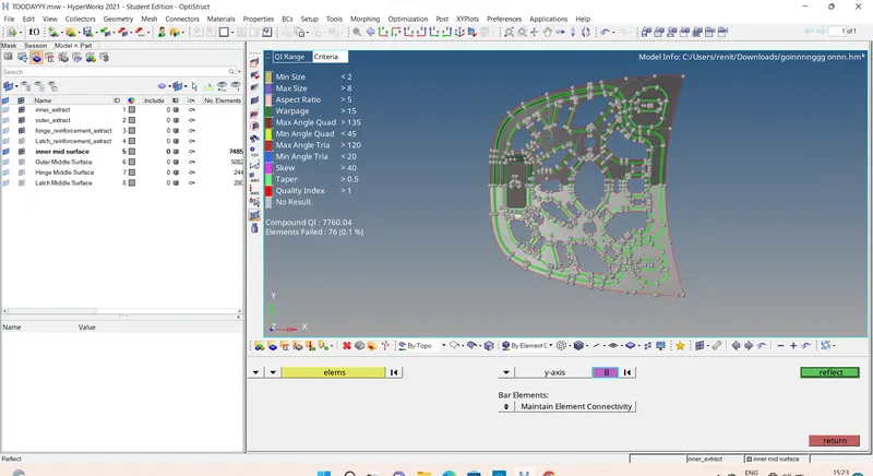
After reflection.
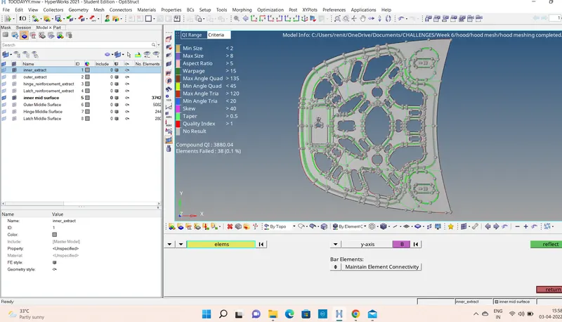 ]
]
- After reflecting the elelments in the model we need to verify connectivity between the elelment throughout .this can we be verified and corrected Using the equvalence tool from the edge panel .
Equvalance : - Tool - edges - Elements - selelct the all elements - Click preivew equvalance- Highlighted node will be equvalance - Click Equvalance
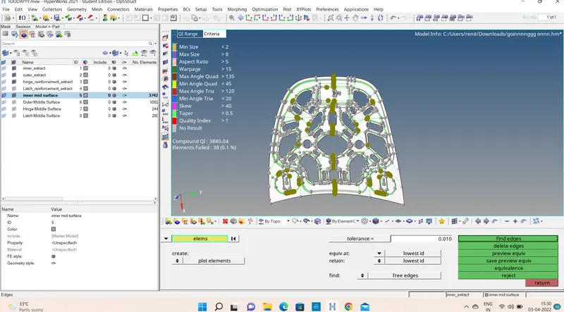
Final Meshed Components :-
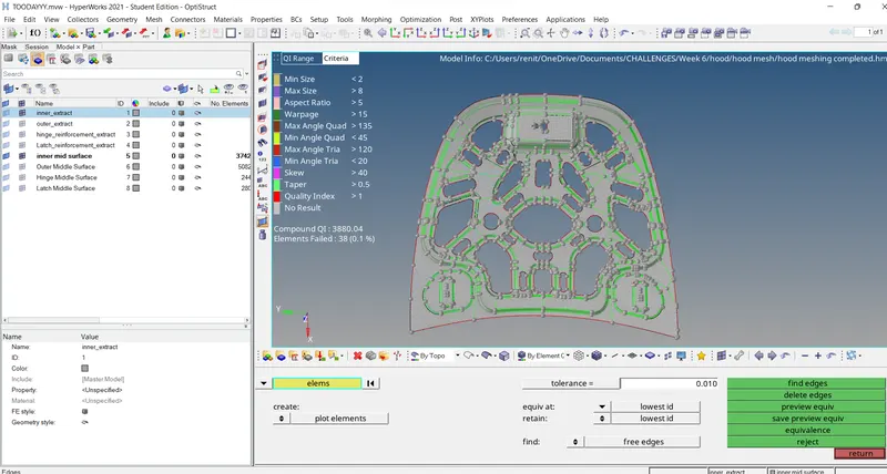
Inner Meshed Part:
Outer meshed part :
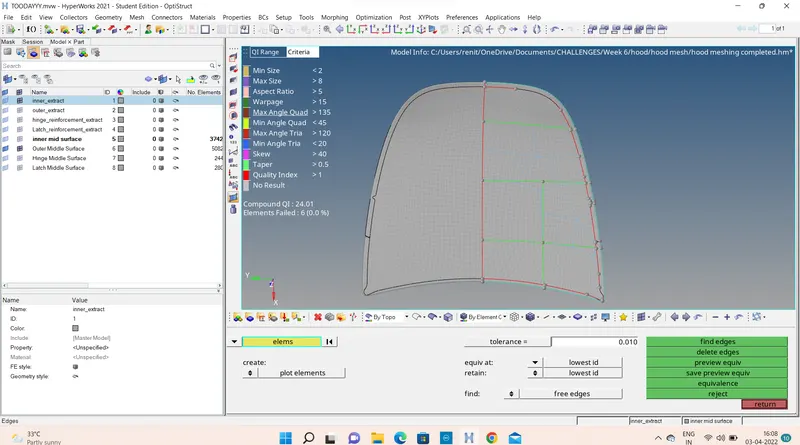
Hinge Meshed Part :
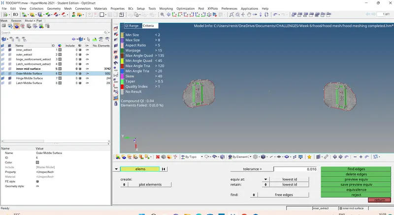
Latch Meshed part:
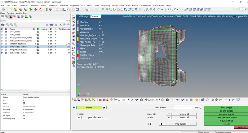
RESULT: Mesh the component given component with given Quality Criteria.
Learning Outcomes:
- learned how to do geomerty clean up.
- Study about meshed and checking with the quality criteria.
- Studed mabout how to add points and how to remove points and lines.
- Got an ideas of wahat an all the errors is comming while meshing and how to resolve the issues with different tools .
- Get a knowledge about the tools before meshing and After meshing.
Thanks ;
Renith Balachandran M