Week 12:Project-1-Meshing of Door Inner Panel Challenge
Aim:- Follow the Quality Criteria and mesh the following component and assign thickness:
Target Element Length = 4 Units
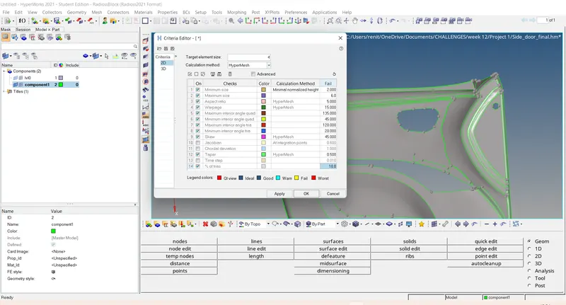
| S.N | Quality Criteria | Value |
| 1 | Aspect Ratio | 5 |
| 2 | Skewness | 45 |
| 3 | Warping | 15 |
| 4 | Taper | 0.5 |
| 5 | Min. Length | 2 Units |
| 6 | Max. Length | 6 Units |
| 7 | Min angle Quad | 45 |
| 8 | Max angle Quad | 135 |
| 9 | Min angle Tria | 20 |
| 10 | Max angle Tria | 120 |
| 10 | Tria % | 10 |
Procedure :-
Step 1 :-Import the model.
Import solver desk - import geometry - Iges file - import.
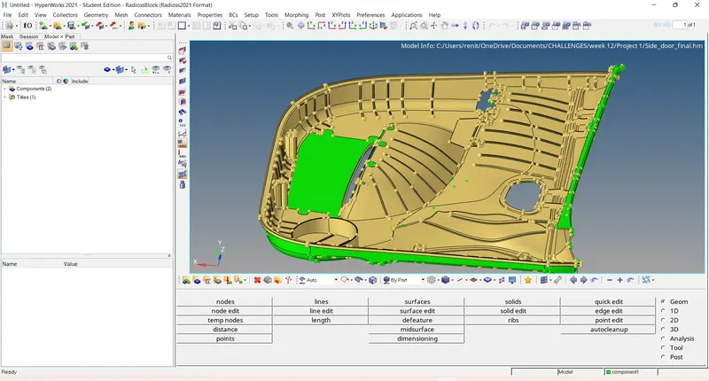
Step 2 :- Giving quality criteria .
Preference - criteria file settings - give the quality parameter given - apply - ok.
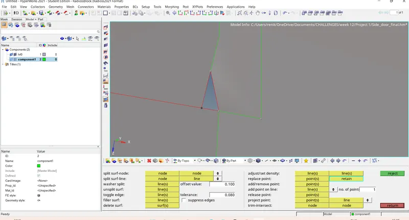
Step 3 :- geometrical clean up .
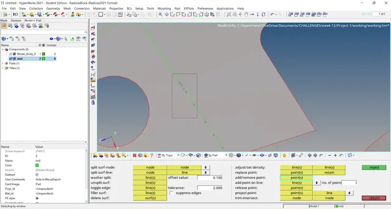
Replacing points :
Geometry - quick edit - replace points - select the point -= retain.
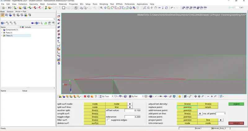
removing free edges :
Removing unwanted nodes .
Geometry - quick edit - remove points - left click to remove nodes.
Step 4 :- Defeaturing the surfaces.
Geometry - defeature - surface fillets - select the surfaces - minimum radius = 0.01 - maximum radius =4 - find -remove.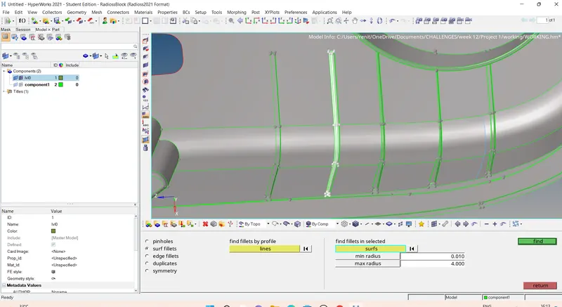
Step 5 :- Offset the surfaces or Manual mid surface.
Geometry - surface edit - offset - selelct the surface - give offset valus as mid - duplicate the surface as current component - offset,
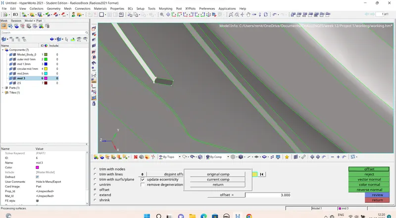
checking for color normal.
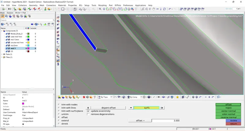
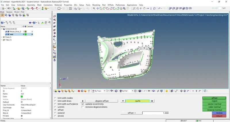
Step 6 :- creating manual mid surfacing .
geometry - surface edit - offset- select the surface - duplicate to current component - give offeset value - offst.
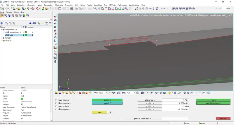
Step 6 :- measuring distance :
geometery - distance - select one pont -select another point.
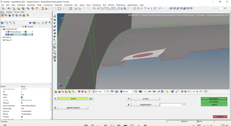
Step 7 :- Transilation.
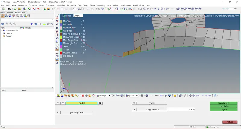
Tool - translate - select the node - give the direction - magnitude - transilate .
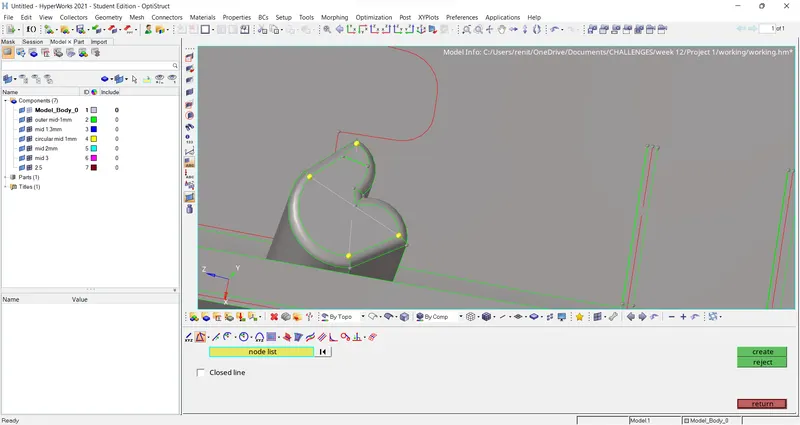
step 8 :- Creating nodes and lines .
geometry - nodes - on geometry - select ponts - create nodes
Geometry - lines - linear nodes - select 1st node and select second node to create lines.
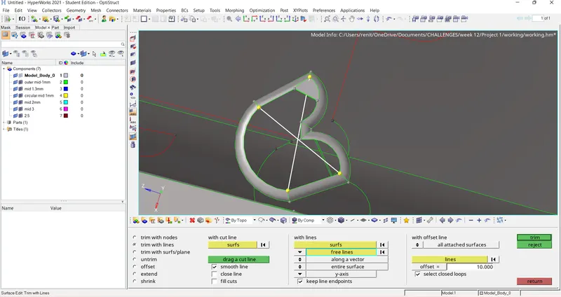
Step 9 :- Trimimg .
geometry - surface edit - trim with lines - select the surface - selelct the free lines -give direction - trim.
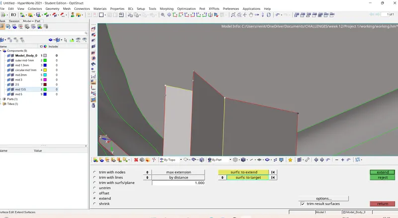
Step 10 :- extending the surfaces.
geometry - surface edit - extend - select the surface to extend - selelc the surface to the target - extend.
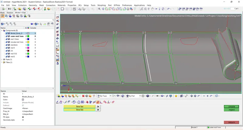
Step 11 :- Creating mid lines.
Geometry - lines - mid lines - select two lines to get a mid lines.
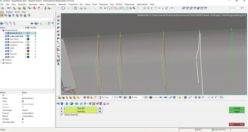
Step 12 :- Creating surfaces.
Geometry - surface - ruled - select the first lines -select the second line to make a surface.
after completing the geometrical clean up.
Step 13 :- Generating mesh.
2D -auto mesh - select the surface - element size 4 - element type mixed - mesh.
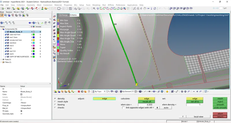
mid surface has minumum element failure hence transilating the nodes.
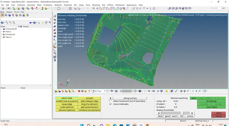
After clearing all quality criteria.
Passes all quality criteria.
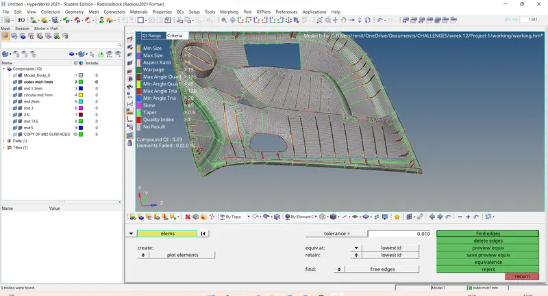
Step 14 :- Giving preview equvalance.
tool - edges - elements - display - preview equvalance - equvalace.
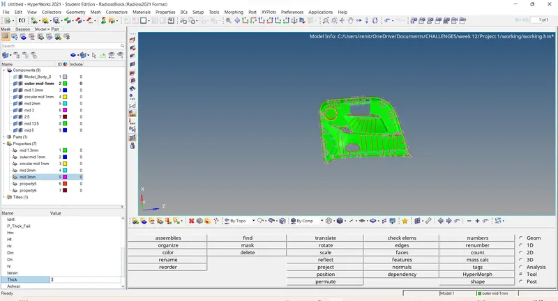
Step 15 :- Creating a property and giving thickness.
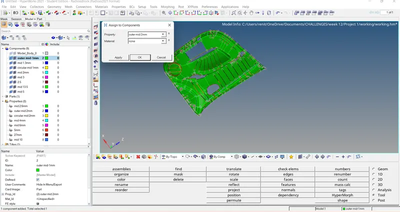
Step 16 :- Assigning property to the components .
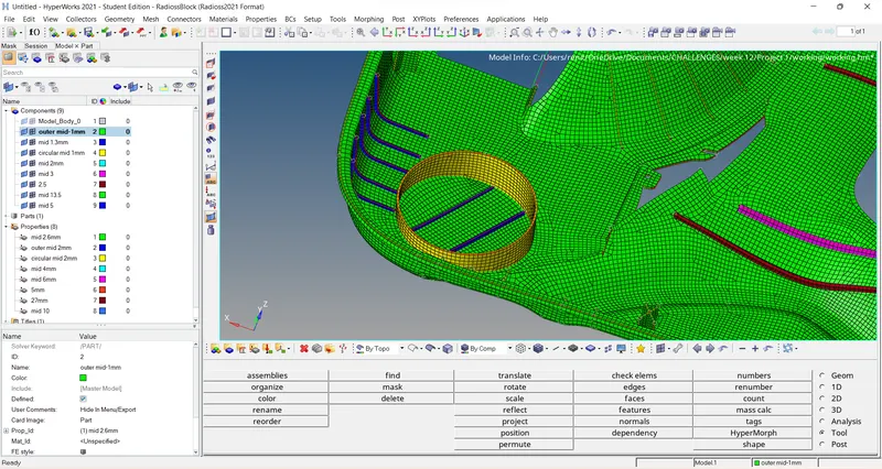
Step 17 :- 2D Detail element representation.
Final Model :-
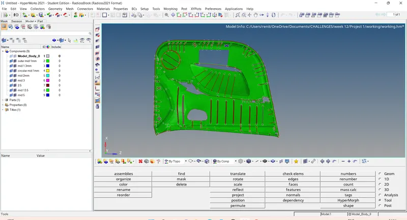
Result :- Given component is meshed with quality criteria and assigned property and thicknesss to the compound.
Learning outcomes :-
- Learned about mid surface of plastic component .
- learned ab out the errors and tools used.
- learned about assigning property and thickness to the plastic component
Thanks
Renith Balachandran M