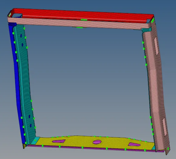
Week 9-Creation of 1D Connectors Challenge
Objective:
- To mesh the given components.
- To connect the given components with specified connectors.
Cad model image:
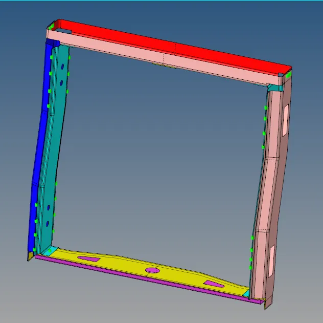
Procedure:
- The given components were meshed directly from automesh panel and all of them were meshed at once.
- Here, the quality is not the main concern, we have to learn to use connectors, so the elements near the connectors should have good mesh flow, only on the connector part we will take quality and mesh flow in picture.
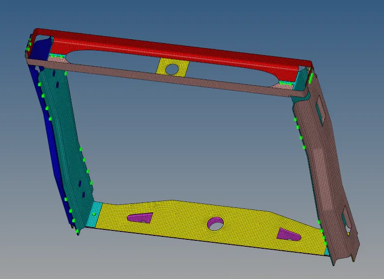
- After completing the mesh, we should start with the connectors.
1. Right_Rail_2 & Front_truss_1:- Seam-Quad(angled+capped+L)
- We go to 1D- connectors- seam- Select seam quad(angled+clapped+L)
- Then put all necessary tolerance and spacing, select nodes and comp and create.(no need to change the default angles, we can keep it as it is)

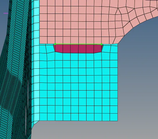
- The mesh gets rearranged after formation of quads so we should remesh the area.
2. Left_Rail_2 & Front_truss_1:- Quad elements
- We go to 1D- connectors- seam- Select quads.
- Then put all necessary tolerance and spacing, select nodes and comp and create.

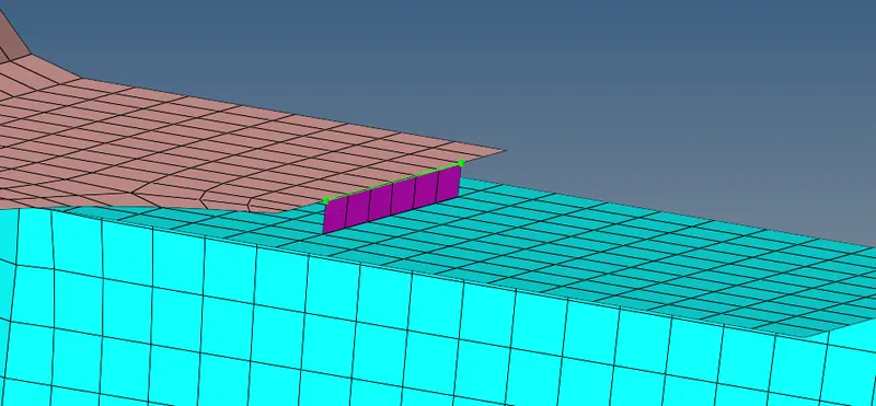
- Then adjust the mesh and we are done.
3. Front_truss_2, Front_truss_1 & Right_Rail_1:- Spot weld with 2 Layers and 5 mm Diameter
- We go to 1D- connectors- spot - weld.

- Put all the values and selection as shown in the box, at number of layers we have kept auto because there are two layers in question, but in actual there are 3 layers to be connected via spot weld.
- And create.
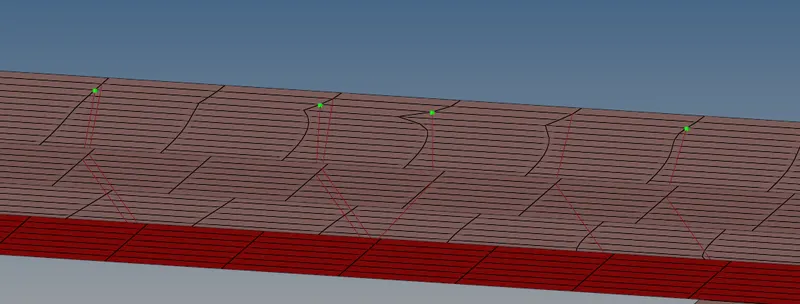
- The mesh is not disturbed in this one, the weld connects at the closest node.
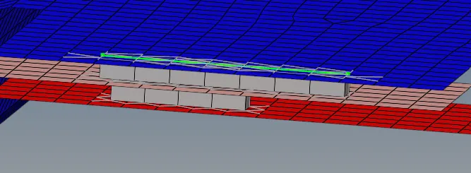
4. Front_truss_2, Front_truss_1 & Left_Rail_1:- Hexa (Adhesive)
- We go to 1D- connectors- seam- Select hexa(Adhesive).
- Put all the values as given below and create.

- The nodes we select should not be on the edge it should be away from the edge, as the adhesives are done on surface and have a thickness.
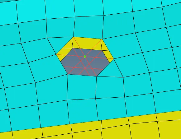
5. Rear_truss_2 & Right_Rail_2:- Bolt Connector
6. Rear_truss_2 & Left_Rail_2:- Bolt Connector
- Both are done in similar manner.
- We go to 1D- connectors- bolt - select bolt general(because nothing more was specified).

- Put the values as shown and create.
- If the surface is flat with no holes, select the option create holes, if none.
- The mesh will change because of the holes so we should correct it.
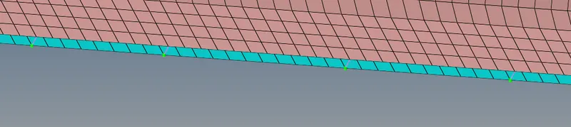
7. Right_Rail_1 & Right_Rail_2:- Spot-weld with Rigid Elements
- Similar to spot weld but put rigid instead of weld in the selection box.
- Put all the values as shown in the box and create.

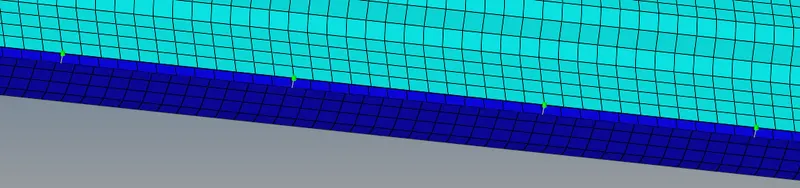
8. Left_Rail_1 & Left_Rail_2:- Spot-weld with Spring Elements
- Same as Spot-weld with Rigid Elements, just put spring intead of rigid.

9. Rest all the component left Join them with suitable connectors
- We can put connectors as per our wish.
Difficulties faced during the challenge-
- Segmentation error occured twice lost all the data because of that, Vineeth sir gave the solution to delete the command.tcl file so the hypermesh can be reset.
- Vineeth sir also taught to do a batch mesh, so no time is wasted correcting the mesh.
Result and final model: