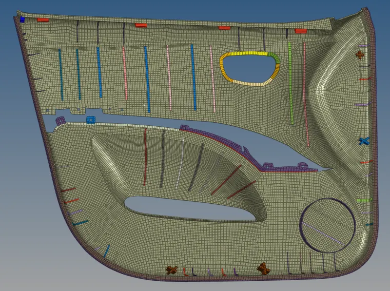
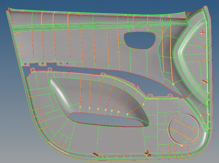
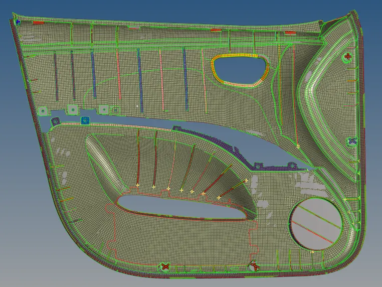
Week 12:Project-1-Meshing of Door Inner Panel Challenge
- Doors are a very important part of an automobile.
- Doors make sure that the person is safe inside the vehicle.
- Doors have various controls such as power windows, and are also equipped with speakers, door opening mechanisms.
- And as safety is increasing in times like now doors are also Equipped with airbags so the passenger is safe from side impacts as well.
Objective: To extract misdurface and mesh a plastic component with different thickness.
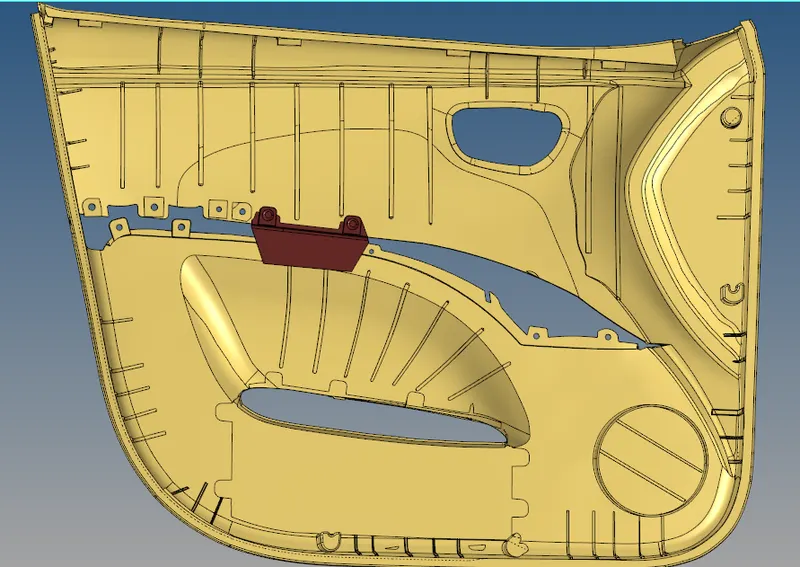
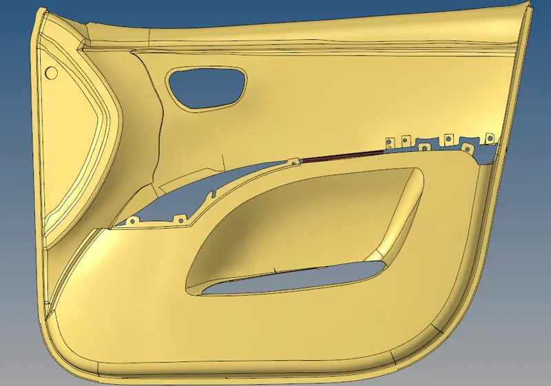
Cad model image:
Procedure:
- The most important thing in this component is to understand the geometry perfectly as its thickness varies from place to place.
- The maroon colored part is to be moved to a different collector as it should not be meshed.
- In components like this, they have a base surface which have a uniform thickness, like in this inner door panel the class A surface have minimum attachments, and is like a uni surface so it will have uniform thickness. (2.8 units in this model).
- To measure the thickness we can use temp nodes and project option.
- So we select a surface by face and offset it with 1.4 units(half of 2.8).
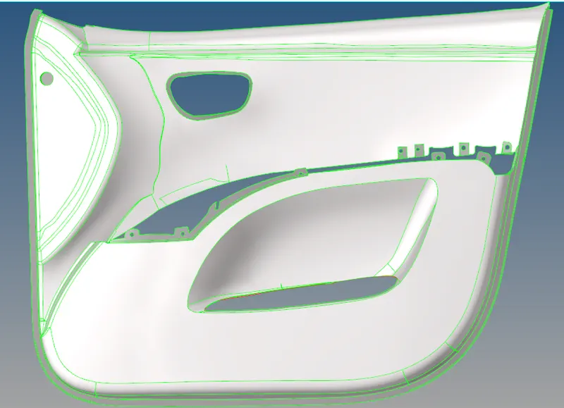

- Before offseting we should make a seperate collector naming it misdsurface.
- Then we check for vectors, duplicate it and offset it(keeping midsurface as current component) so we will get the midsurface of the base surface.
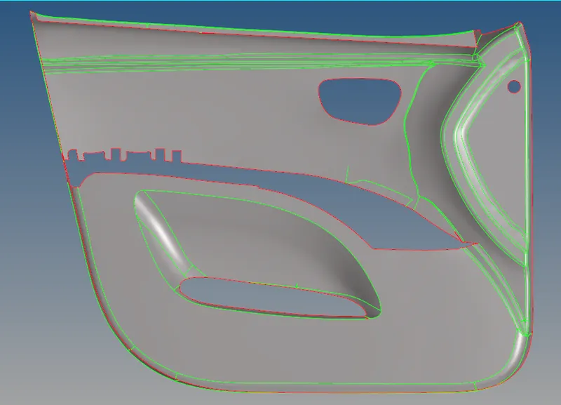
- Now for this part
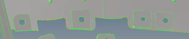
- In midsurface we don't have this surface

- So we will use ruled option and select the lines and create surface, after that we will trim that surface with the holes from parent geometry by trim with lines option in surface edit.

- Afterwards, we pick a position to start from, I started from bottom right, by offsetting the circular section.
- We can also defeature the edges at those make it hard to measure thickness.
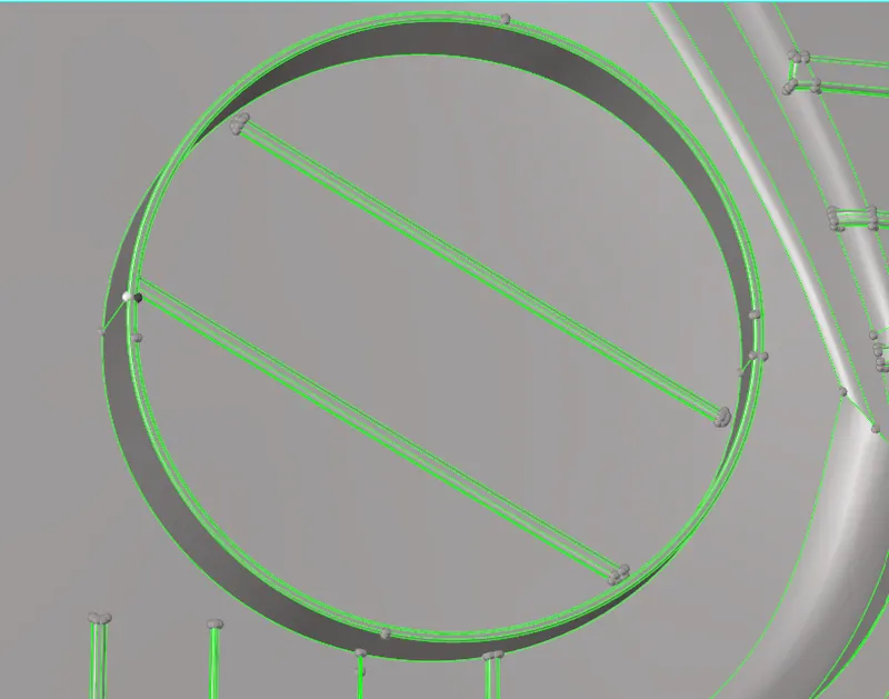
- This have a thickness of 2 units, so we offset it by 1 units and after that we use surface extend option to join it with base surface.
- We should always check for some surface abnormalities and correct it by using quick edit or other useful tools.
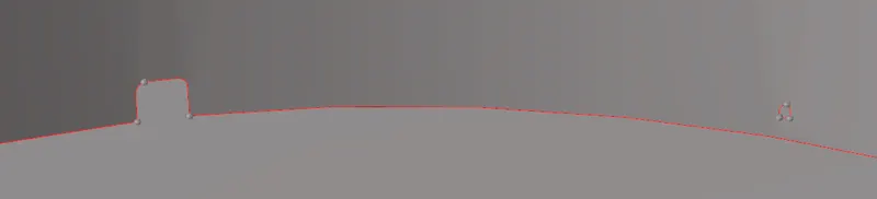
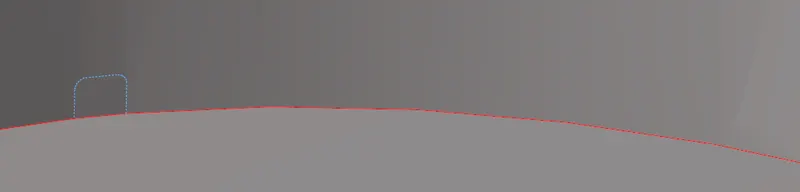
- We can either extend the surface or we can trim it with lines and then use ruled option.
- At times using extend messes up with the midsurface so I prefer trimming with lines and then using ruled option and toggle the line.
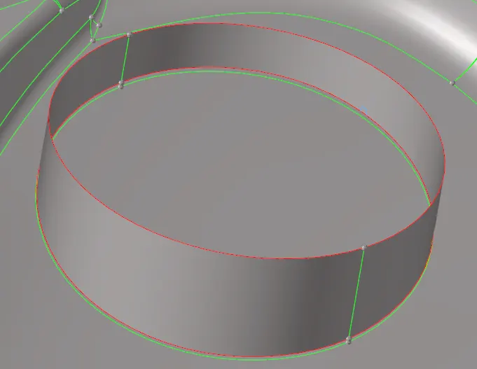
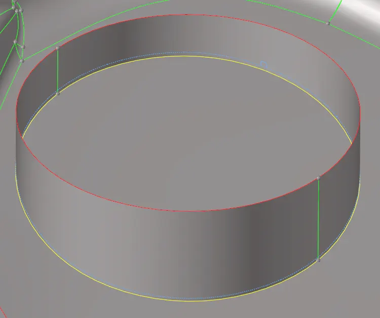
- Now moving to ribs, we should defeature the ribs as it becomes lot easier and we won't have to extend surfaces afterwards as because of the fillets the distance is shortened a little.
- For ribs we use tools like midline, trim with lines and ruled surface.
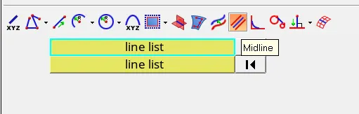
- We select lines and then we press create.
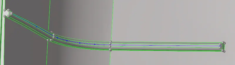
- Then trim with lines and ruled.
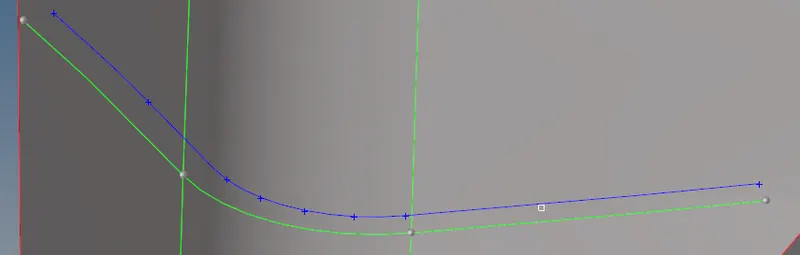
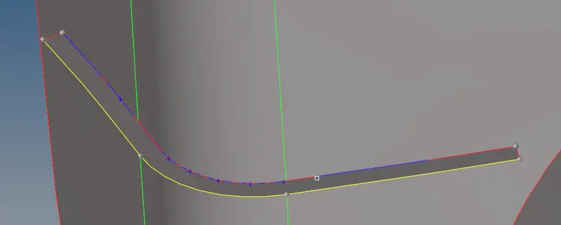
- Like this we should do with all the ribs and other surfaces.
- We will find surface irregularities like this in the midsurface we should manually resolve them using quick edit option.
- In this case, replace points and delete the extra surface. Or replace all the points to make a smooth surface.
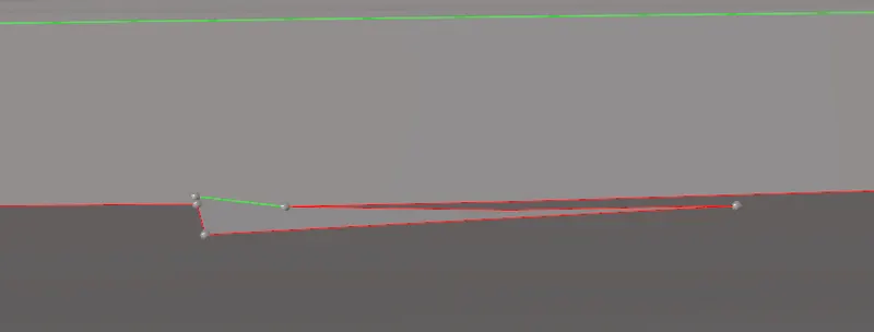
- Now for components like these,
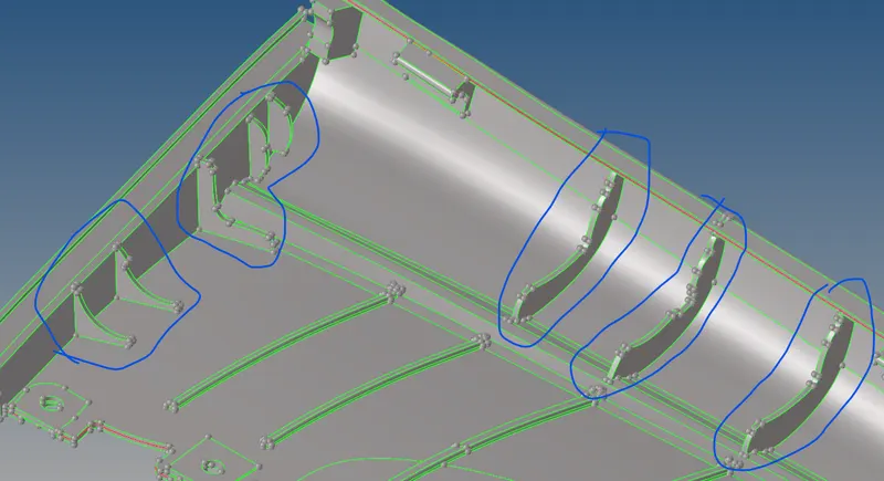
- We will use the final edit tools in the midsurface option.
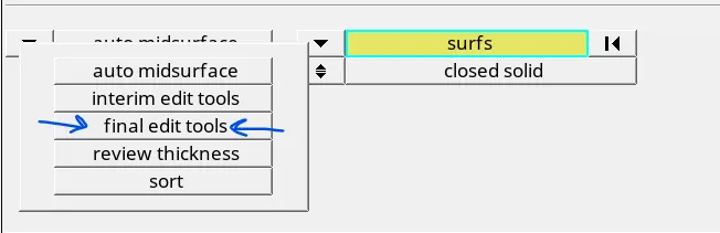

- This will help us create the midsurface by clicking both sides of the surface.
- For example, for this surface
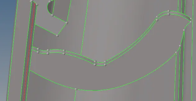
- Select both sides and we will get a mid surface.
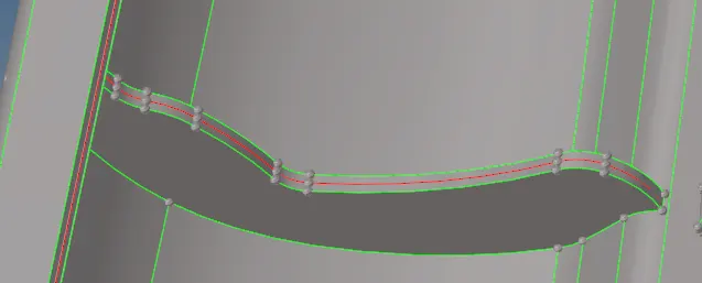
- Now to attach the midsurface, we can use extend or ruled option.
- For me the extend option didn't worked for me as it was changing the shapes of surfaces, so I went with the trim with lines and ruled option.
- But when we trim with lines the surface isn't trimmed completely, we have to split the surface with node and line or node and node from quick edit.
- Using this method gave me a good midsurface.
- For the door handle,
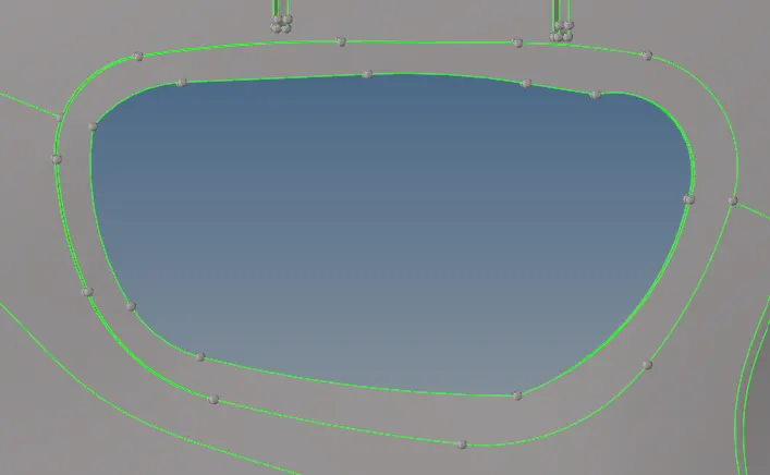
- We can create a midline of the top surface and then trim the bottom surface with the midline and create a surface by ruled and then connect it to base surface by cross extension.
- So we will get a surface like this,
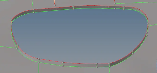
- For the holder parts,
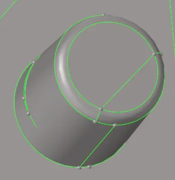
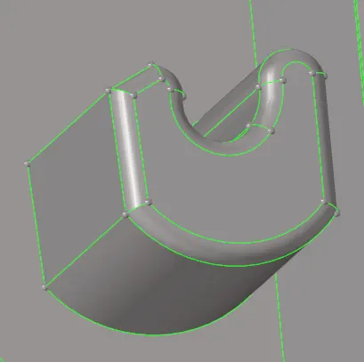
- We should trim it like this,
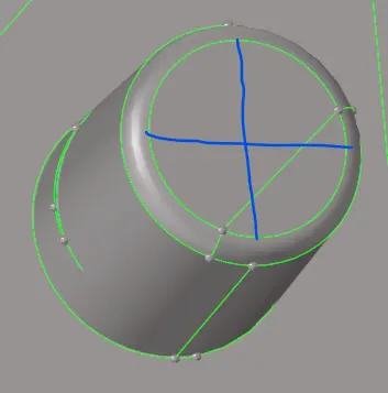
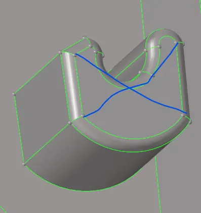
- For assigning thickness to this component we should take it as d/4.
- Then we should perform same operations, trim with lines- ruled to create surface.
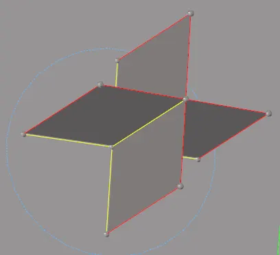
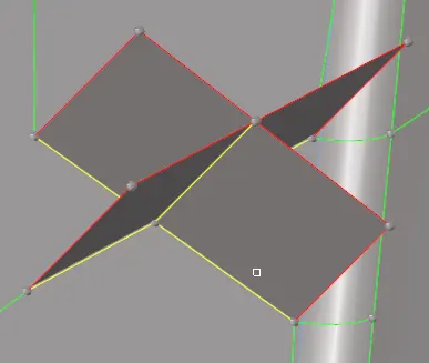
- Some places the thickness varies throughout, so we have to take an average thickness.
- Here the 1st edge is around 5 unit thick and 2nd edge is 6 unit thick and it has a thickness of 6 throughout.
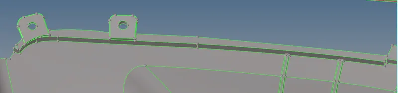

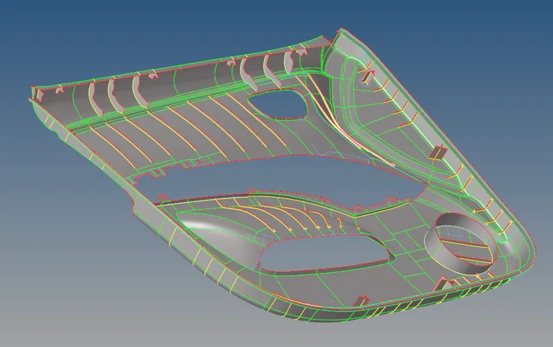
- For remaining parts we shoulf perform all the same steps for creating a good midsurface.
- For meshing,
- Before starting the meshing we should do the geometry cleanup.
- But for doing the meshing too we should understand the geometry as it has different thickness and we will have to assign different thicknesses to different elements.
- So I first started with the base plate then I moved the complete elements to the particular collector with its thickness.
- Then I started with the ribs and all the other parts.
Geometry cleanup
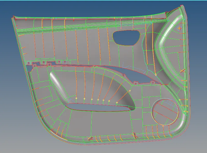
Base surface mesh
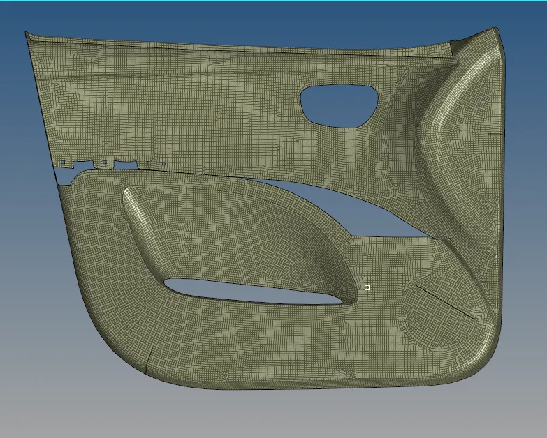
Remaining mesh part makes it easy to organise once the base plate is moved.
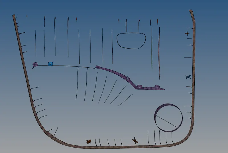
- After completing the mesh, we should organise the elements into different collectors with specific thickness.
- For ribs and other varying thickness parts we should take an average thickness.
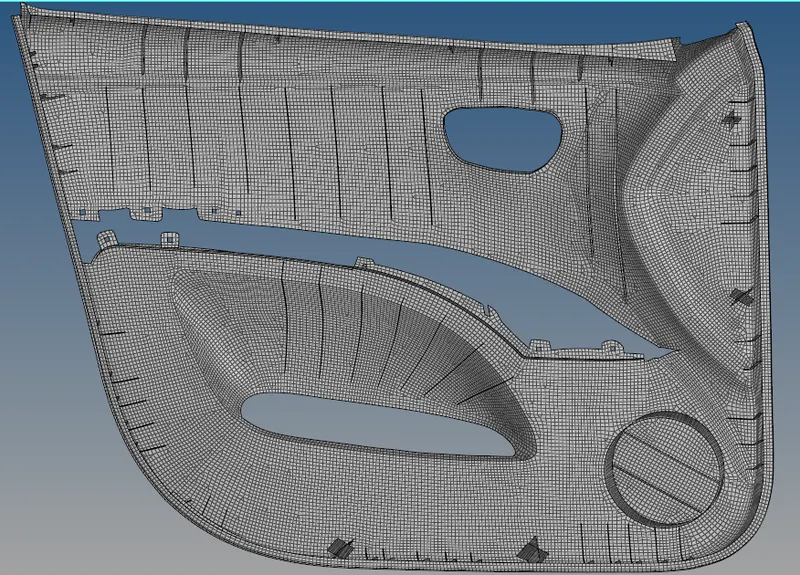
- Assigning different properties to particular collectors.
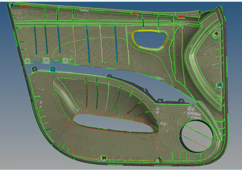
- Now to check the mesh we should put it in 2D detailed view.
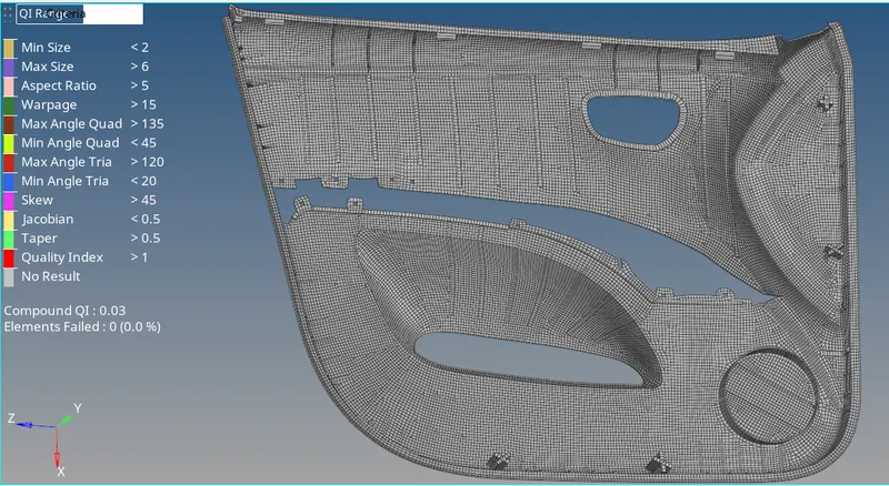
- We should clear the quality criteria during meshing, no elements should fail.
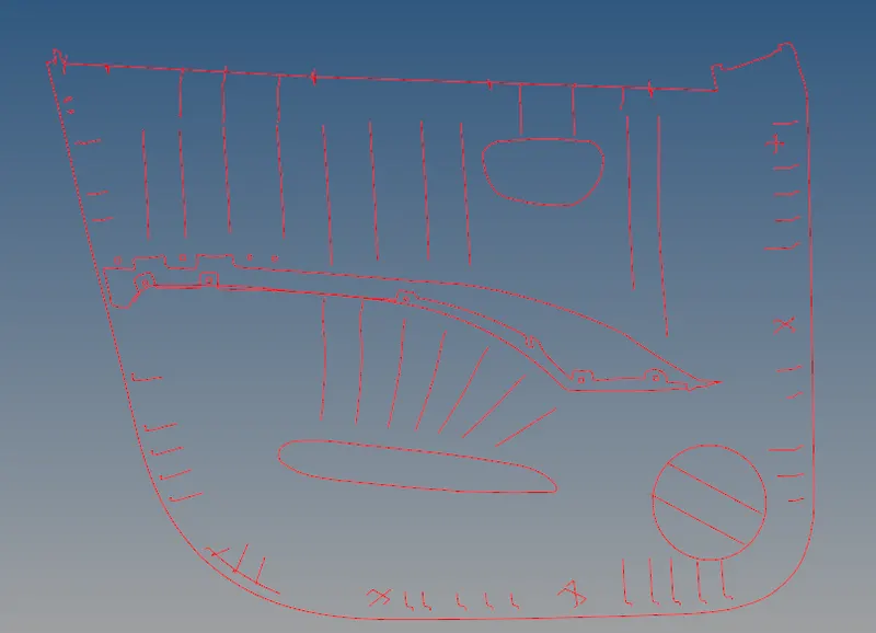
- At last we should check for edges, I found a lot of edges and resolved it by using replace nodes option.
- The mesh should fulfill all quality criteria and shouldn't have edges in between the mesh.
Result and final model: