Assignment 4-RADIOSS Material Laws Challenge
Objective:
- To run simulation and animation on components using (7 cases)-
- Different materials
- Different material properties.
- To understand material behavior with properties modification and to tell which material gives real life results.
Procedure:
We have to follow the questions of the challenge
Case 1
- In case 1, we first have to import the FAILURE_JOHNSON_0000.rad file and change its title in title card to Law2_epsmax_failure.
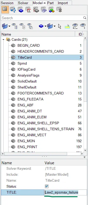
- Then we have to do simulation in it at default values, go to analysis- radioss- select save as and make a folder for case 1 and save the file there- include the collectors and in options put -nt 4, that means we are using 4 cores of the CPU for the simulation to increase the speed of the simulation, then click radioss. This will start the simulation
- Then note the number of cycles, time taken, energy error and mass error. (cycles and time is given in 1st result file for errors we have to open the output file)

- The values are stated below in the table of result section.
- Now, we will have to run the animation to tell which elements are deleted and to know the strain energy of the system. We also have to plot graphs to get the clear idea of energy lost during deleted element deletion.
- Divide the screen in 3 parts, in 1st we run the aimation with h3d file from results (hyperview), in 2nd we plot energy graphs from global variables and in 3rd we plot rigid wall energy forces (Hypergraph in 2nd and 3rd).
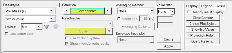
- We have to chane the contours in hyperview to von mises and then select components which gives us the stress value and then click apply.
- We can also save the .hm file of every case.
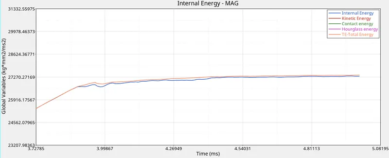
Internal energy and total energy
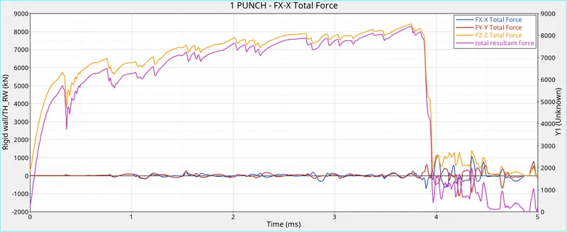
Rigid wall forces
Similarly we have to run simulation and animation and plot energy and force graphs for remaining cases. We just have to change the material properties as given in the question. The detailed energy plots and animation explanation are listed in conclusion and results.
Case 2
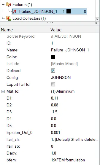
- Here, we have to import the 1st case file and do changes in the failure card properties as mentioned in the question.
- We also have to change the title name to Law2_epsmax_crack.
- Then we have to repeat all the steps for graph and animation as we did for case 1.
- Here also we can save model as case2.hm.
Case 3
- Here, we have imported the case 2 file and we have to delete the failure johnson card and run the simulation.
- Also change the title name to Law2_epsmax_nofail.
- Repeat all the steps lie that of case 1.
Case 4
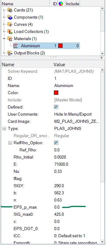
- For case 4, we have to import the case 3 file and change the EPS_p_max value to 0 in materials and delete the failure materiaal card (which we already deleted in case 3).
- And then do the simulation, animation and plot graphs and note values of errors, time, stresses,etc.
- Then save file as case 4.hm.
Case 5
- Here, we import the case 4 file and we change the material of the component to Law 1.
- Then give the values of rho, E and density as it was for earlier cases and repeat all the steps in case 1.
- Then save the .hm file as case 5.hm.
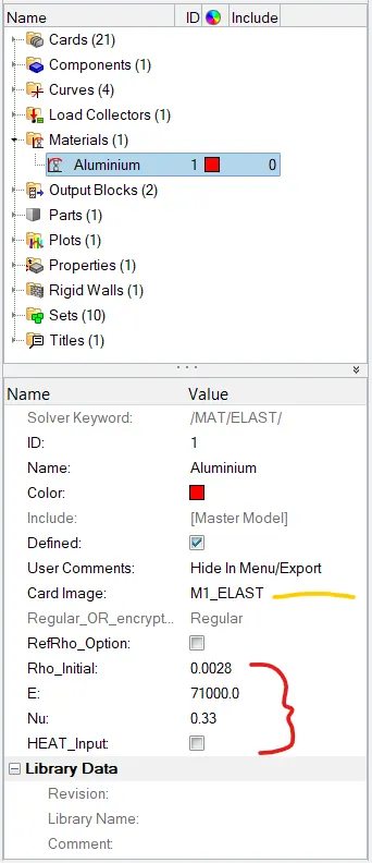
- M1 refers to material law 1.
Case 6
- In this case, we have to import the case 1 file and change the material card to Law 36 and change the material card according to the table in the question. Here the tricky part is to create a curve that we will have to apply to the materials.
- For creating curve right click- create- curve then name the curve and put the values from the material part 7 videos.
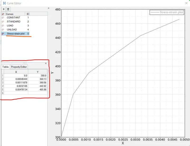
- Then go to materials- N_funct-1- fun_id-select the curve.
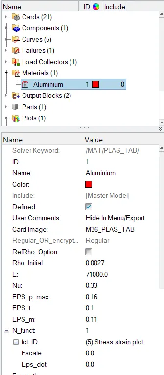
- Repeat the steps as of case 1 and plot graphs, simulation, animation and results.
- Save the file in .hm format.
Case 7
- The file for case 7 is given seperately, here we only have to change element property to the recommended value and no changes to material card or anything else is required.
- After making changes we have to run simulation and note down the results.
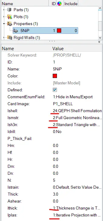
- Recommended changes are marked in red.
Results:
| Value | Number of cycles | Time(s) | Energy error(%) | Mass error(%) |
| Case 1 | 49380 | 56.25 | 0.8 | 0 |
| Case 2 | 49217 | 61.15 | 4.1 | 0 |
| Case 3 | 49408 | 55.32 | 0.8 | 0 |
| Case 4 | 48737 | 61.60 | 3 | 0 |
| Case 5 | 47969 | 57.25 | 1.3 | 0 |
| Case 6 | 53148 | 42.97 | -1.8 | 0 |
| Case 7 | 49508 | 42.11 | 0.8 | 0 |
Case 1
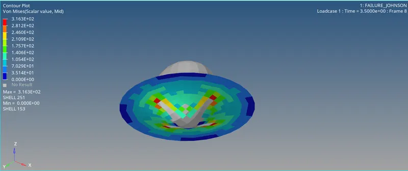
- As we ran the simulation, we concluded that the elements got deleted and broke off after reaching the maximum stresses.
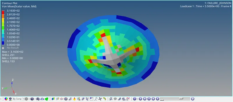
As you can see the elements broke off from the plate.
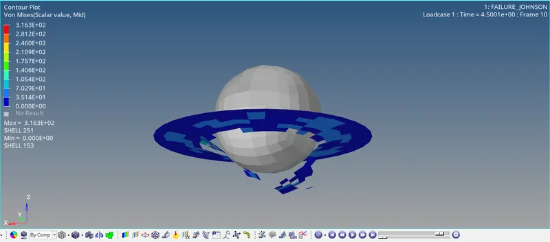
Such deletion of elements will result in decreasing of internal energy of the system.
This decrease can be seen in the energy graph plots.
There's a slight decrease in energy because of deletion of elements.
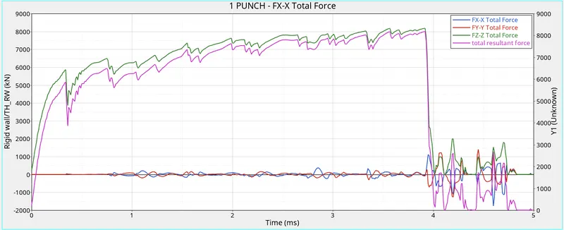
The rigid wall forces diagram gives the forces experiened by rigid wall.
The maximum stress in this case is 3.163e+2
Case 2
In case 2 we have used Dadv=1(can only be used if Ixfem=1) and Ixfem=1, this parameter makes the element to crack before getting deleted, i.e. the element will crack at a particular stress and then it will get deleted if stress increases further.
Dadv refers to as crack advancement. Ifail_sh will make the element cracked or deleted and Ixfem also makes sure that the element gets cracked intead of deletion.
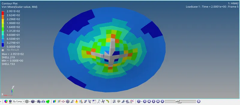
The crack cannot be seen very well but 2 elements can be seen cracking, the reason behind this is the mesh size.
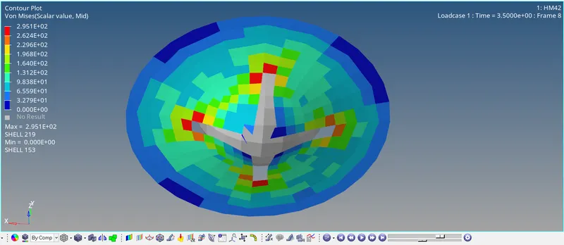
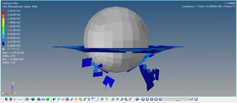
Still the elements got deleted as the material could not withstand the stress of 2.951e+2.
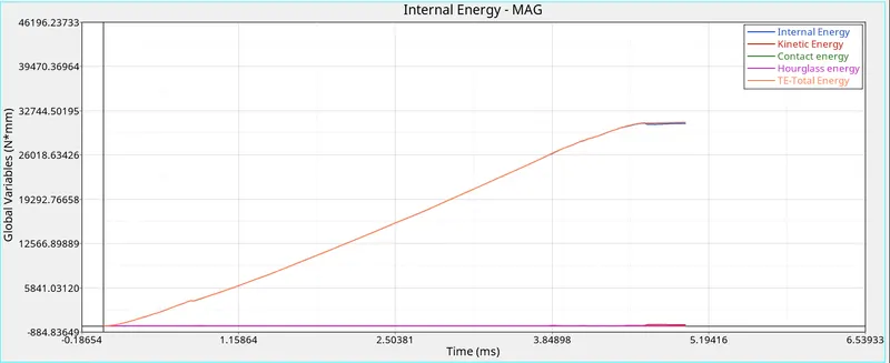
As the elements got deleted it can be seen at the graph as well the difference in total and internal energy.
And as the element got deleted, we can also see some hourglass energy getting generated at the point of breaking of element.
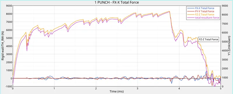
Rigid body forces:
Case 3
In 3rd case we have eliminated the failure card but the EPS_p_max is stil there so the material fails after reaching the failure plastic strain value.
And due to breaking of elements the energy is lost in the internal energy of the system.
As we have deleted the failure card the properties that makes the element crack also gets removed which would make the element to break off.
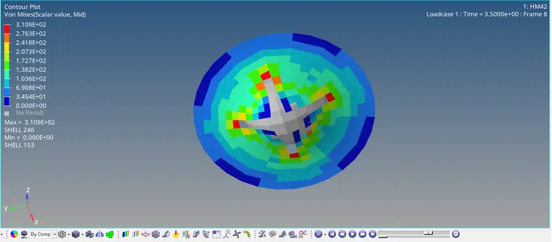
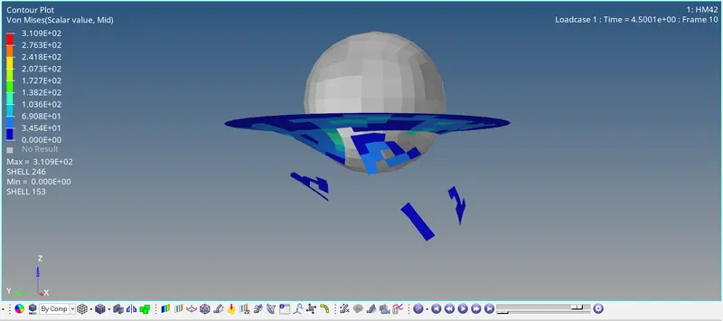
We can see that the elements are completely getting seperated.
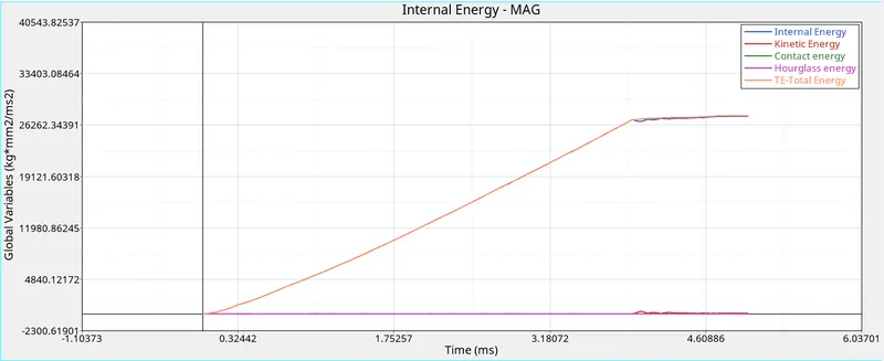
As elements got deleted hourglass energy is generated and internal energy decreases.
The value of stress is 3.109e+2
Case 4
In case 4, we have deleted the failure card and also removed the EPS_p_max, which means the element won't fail and that can be seen in the animation.
The elements did not fail even when the value of stresses were very high.
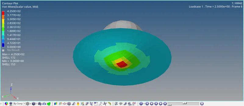
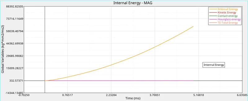
The internal energy and total energy is equal as there is no loss of energy in the elements.
The elements became elastic we can say by seeing the graph.
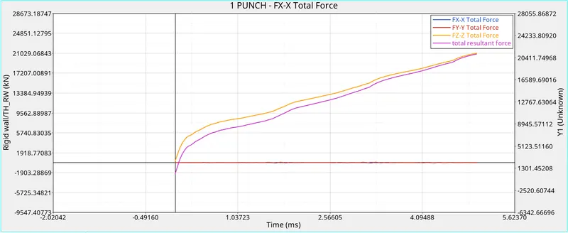
Rigidwall force:
The maximum stress is 4.250e+2.
Case 5
In case 5, we have changed the material to law 1 which is eleastic but no aluminium material can be truly elastic in nature.
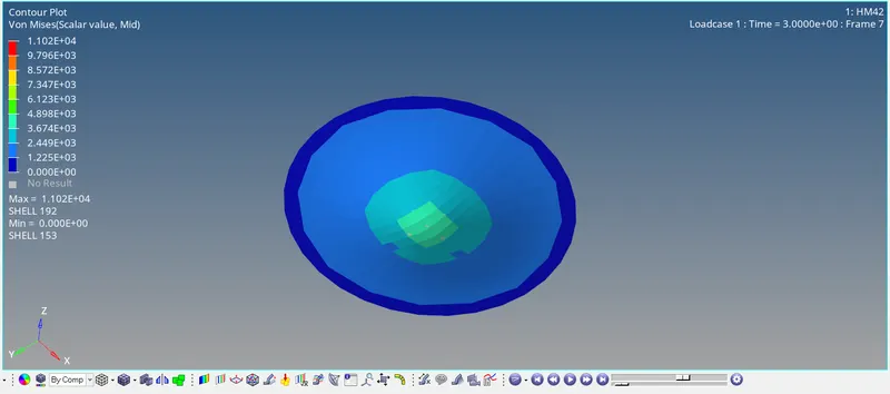
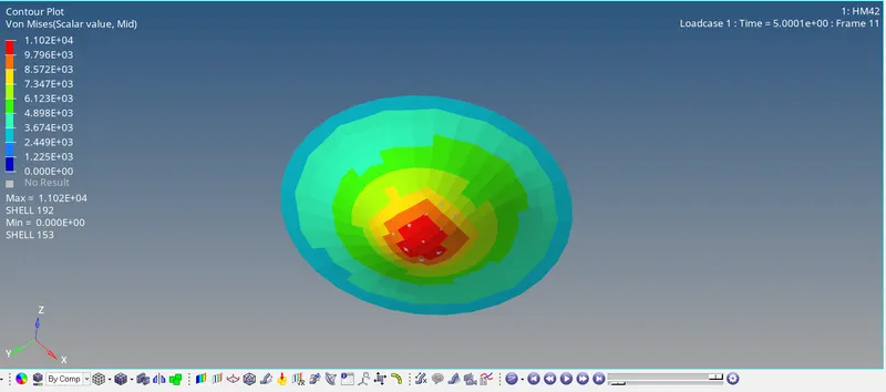
The stresses caused in the animation is also very huge.
There is no energy loss and graph is uniform for internal energy and total energy.
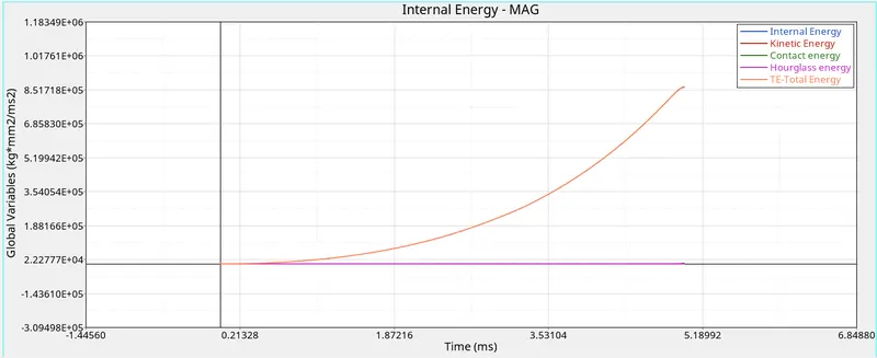
Rigid body forces:
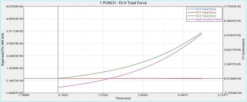
The maximum stress value is 1.102e+4.
Case 6
This case we have used law 36 material card which is a plastic card.
Here, we have plotted the graph for stress strain and applied it to the material making it more realistic.
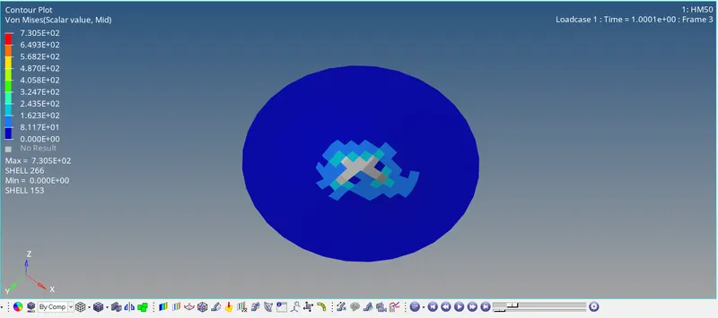
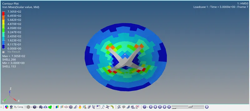
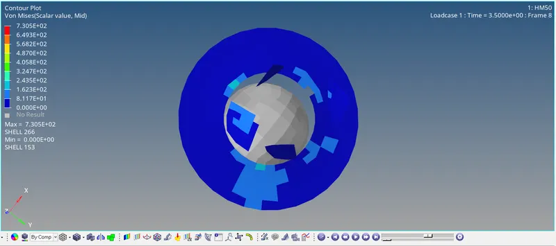
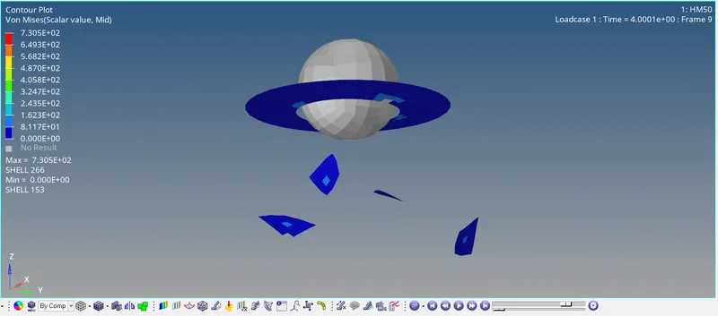
The element deletion is like a die it took the shape of the rigid body.
The animation isn't ver realistic but the results and graph are good and real.
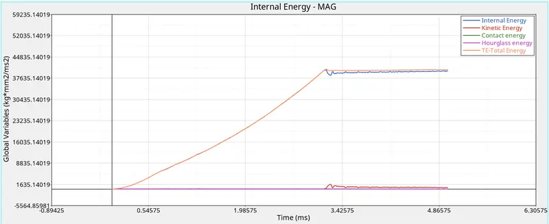
Here also hourglass energy is generated and internal energy is less than total energy when element get deleted.
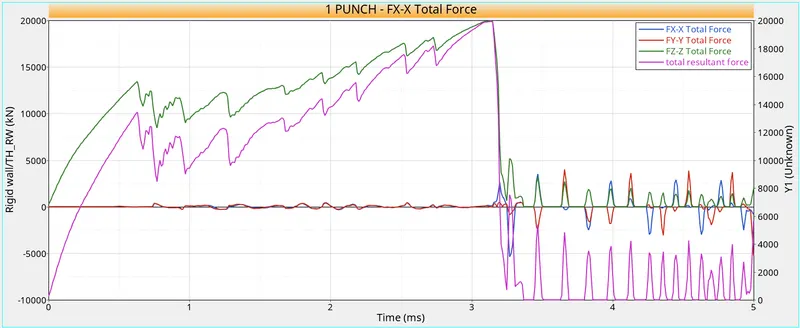
Rigid body forces:
The maximum stress in this case is 7.305e+2.
Case 7
This case we use a law 36 card which is brittle plastic.
We directly run simulation by applying recommended shell properties.

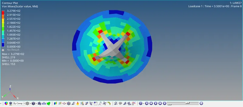
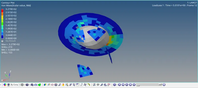
Elements get deleted after reaching the maximum stress and resulting in drop of internal energy of the system.
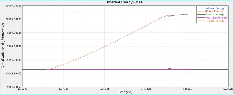
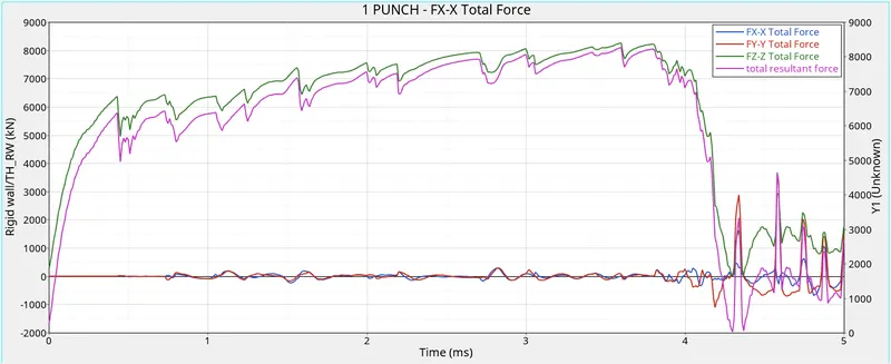
Rigid wall forces:
The maximum stress is 3.279e+2.
Conclusion:
Case 1, 2 and 6 gives the most realistic results in terms of stress and energy errors.
Case 4 and 5 gives most unreal cases as no aluminium can be elastic and even hyperelastic materials breaks after a certain point.
Case 6 is the most preffered real case material as there we have used the stress strain values of aluminium and we have only used 5 values if we would have used more values the energy error will be even less and out of all the cases only case 6 has negative energy error which is only possible in real cases.