Week 6-Meshing of Hood Challenge
Objective:
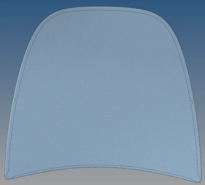
- To generate midsurface and a clean mesh for the hood/bonnet of a car.
- To learn to do geometry cleanup and get to know the that how a proper flow is generated in the model.
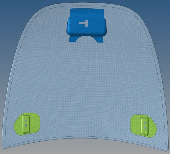
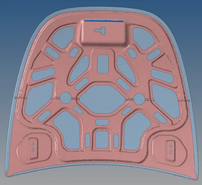
Cad model image:
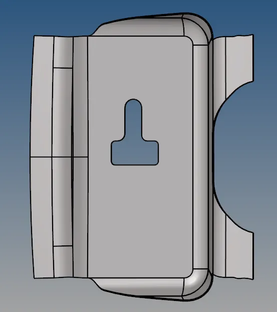
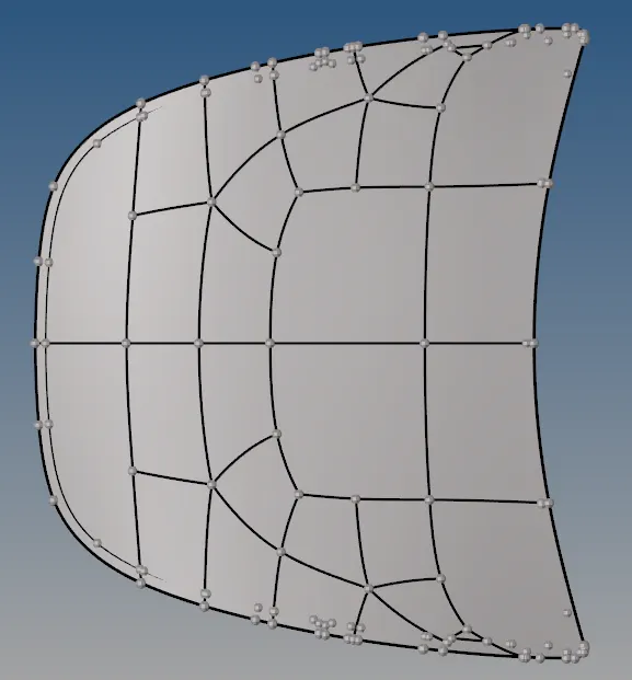
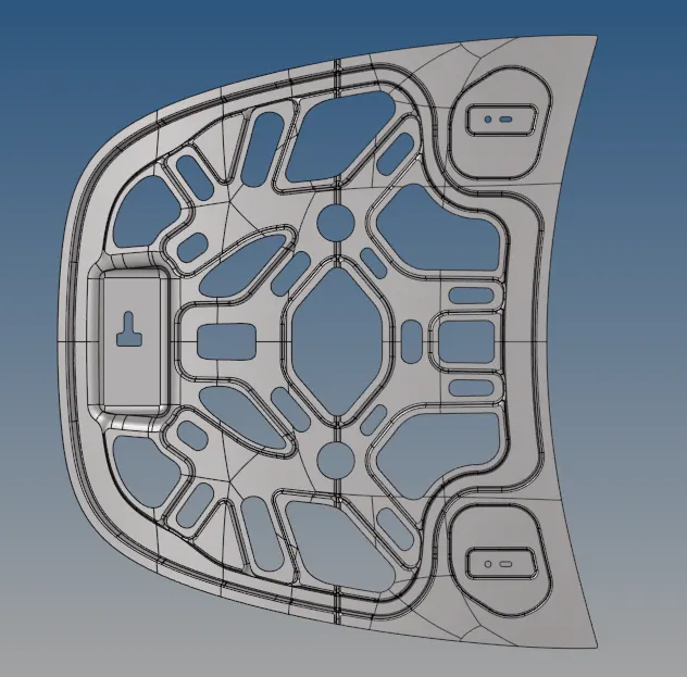
Procedure:
- The 1st step after importing a geometry for midsurfacing, is to remove all the solids.
- After removing solids, we can extract the midsurface by automidsurfacing or by manual midsurfacing.
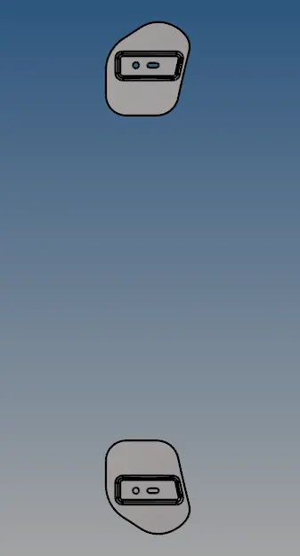
- After generating midsurface we should delete half the surface for the for the identical components. i.e. the inner extract, outer extract and hinge extract. We could have done for latch as well but since it is a small part we can keep it whole.
- The purpose of deleting is to increase the speed of meshing, because we can just reflect the mirror surface in few steps.
- While extracting midsurface, we have to make sure to make seperate midsurface components for every parent component or else they will be considered as single midsurface.
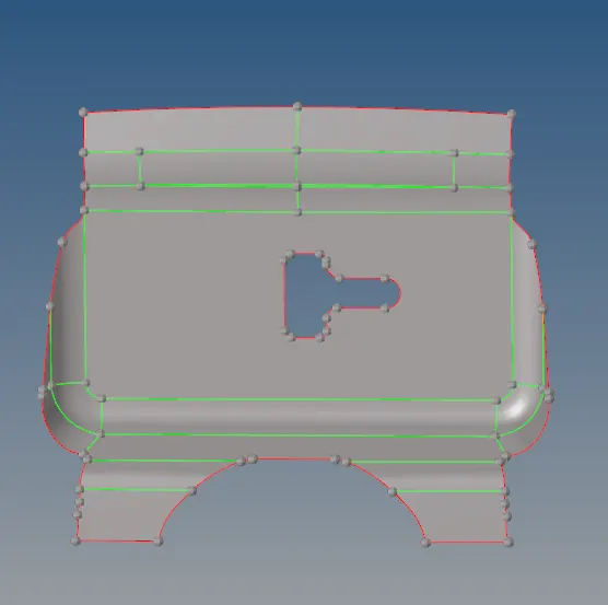
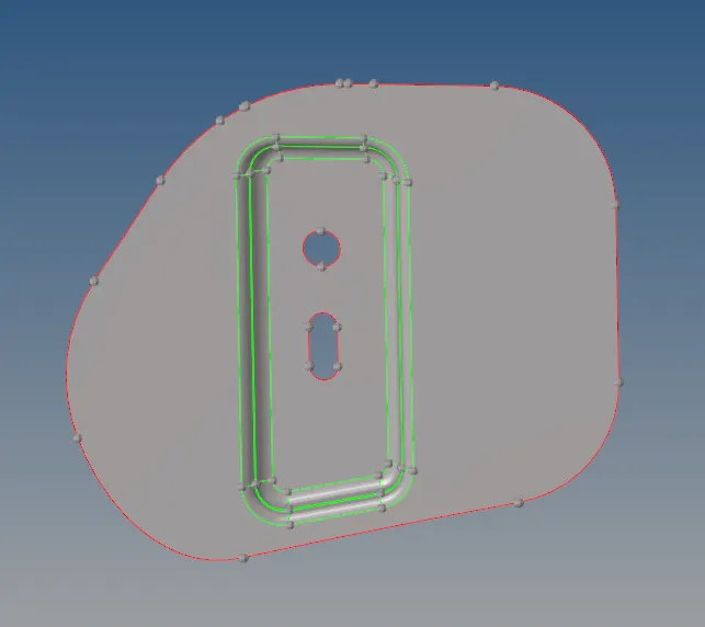
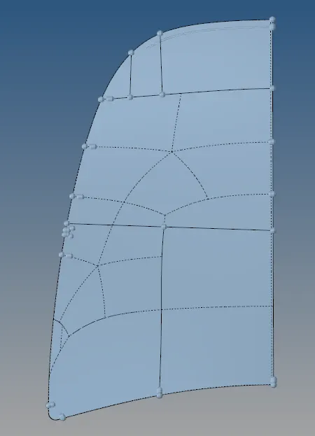
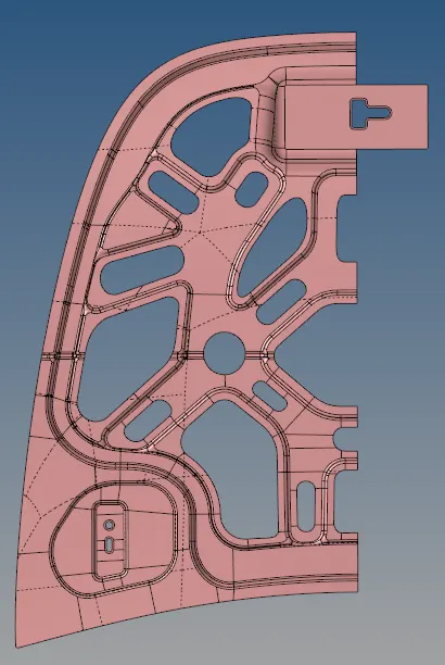
- As we delete the half surface after midsurfacing we have to check thoroughly if some lines or nodes are left.
- In the inner extract the cut out for the latch as it is not identical and cannot be reflected, hence we keep it as it is.
- After midsurface is extracted and the half identical parts are deleted, we start to clean the geometry so we get an easy mesh flow.
- This process takes alot of time because this decides the mesh flow depending on how good the elements are cleaned.
- I started with latch component as it was on the videos and had a simpler shape than the rest of them.
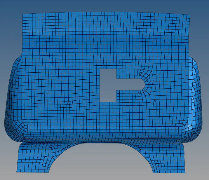
- After doing the latch part, I moved to hinge. The hinge part had to be cleaned up a lot by splitting surface with node and node, node and line, toggling lines, etc.
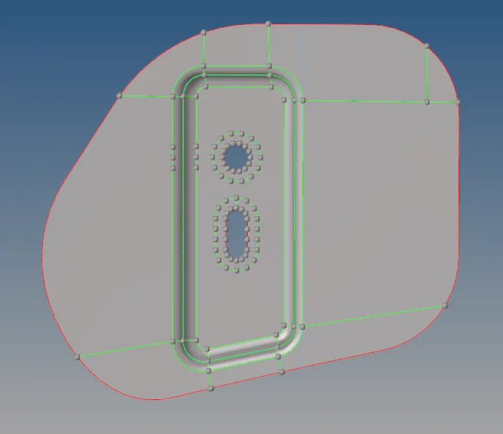
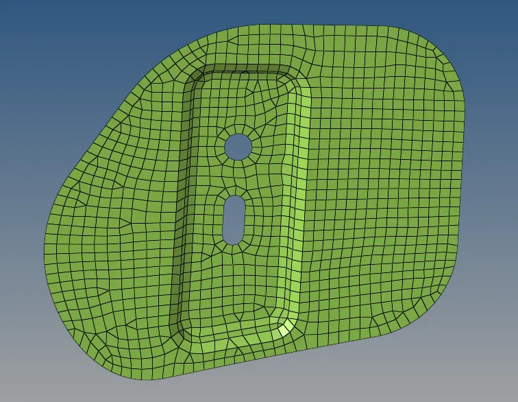
- After hinge, I went to hood part. I had to redo meshing and cleanup of hood part 4 times because of toggled lines, edges, etc.
- All the points look very easy on reading but these are some large parts which takes alot of time to go through.
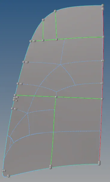
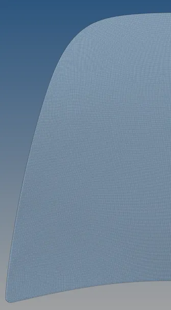
- In the edges of outer hood the section the mesh fails so to avoid that there is a specific way to toggle the lines/edges.
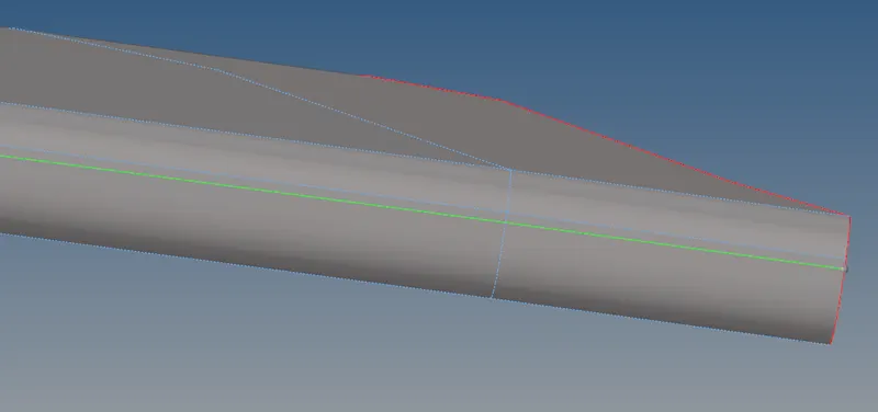
- Had to redo the meshing and cleanup because of this mistake.
- The last and the hardest part to mesh was the inner hood section, it took me days to mesh this component, still some elements failed. I tried everything and had asked for help to Vineeth Sir so many times that I finally let it as it is.
- The geometry cleanup of this part is equally difficult, as it has many holes and different topo.
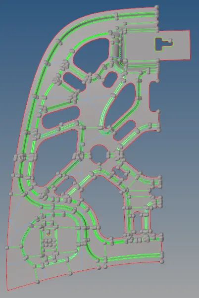
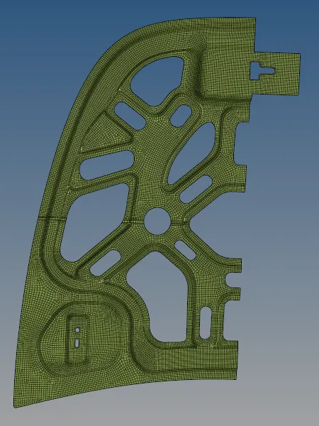
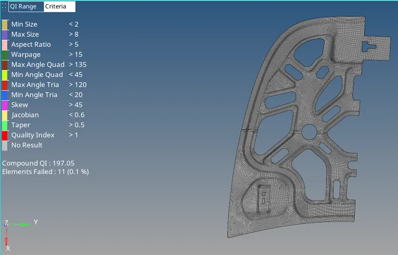
- We have to put the criteria file settings from preferences so whenever we put element by quality we can see everything.
- We constantly have to check for element quality and clear everything after meshing every component, this reduces a lot of work
- After meshing is done, we should assign property with particular thickness and material for all the components.
- We only put one material as all components were of sheet metal.
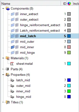
- This is how the tab with parts and components should look like.
- We have to search for edges after we reflect a mesh.
- For reflecting we go to tool- reflect- select what to reflect(element, surface, etc), then choose direction and lastly the base point.
- After reflecting we check for edges and it can be solved by selecting elements and use equivalence option in edges it connects all the nodes which are understood by the software and others we have to do manually by replacing nodes.

- For replacing nodes, press F3 and it will take us to reflect node.

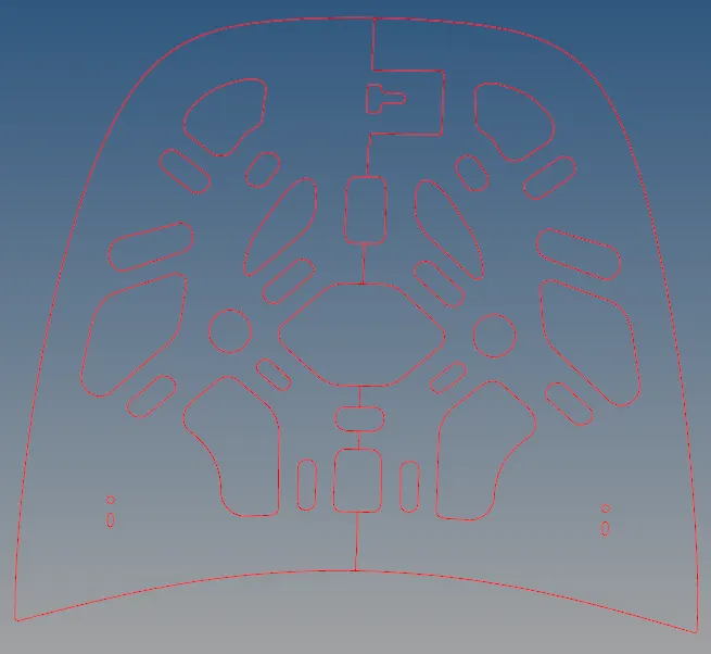
- Edges after reflecting
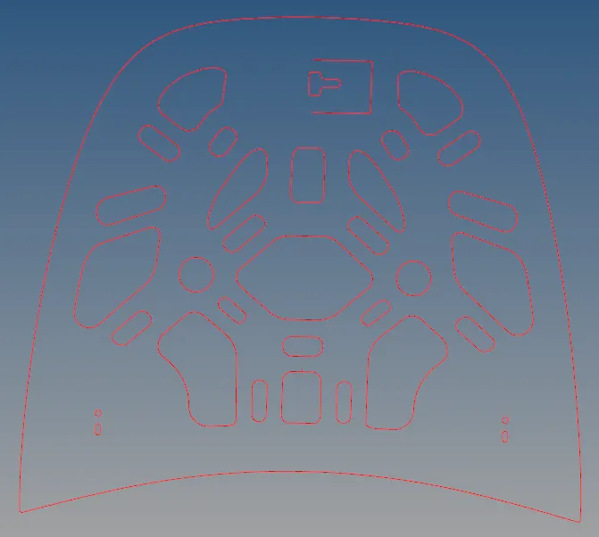
- Edges after equivalence
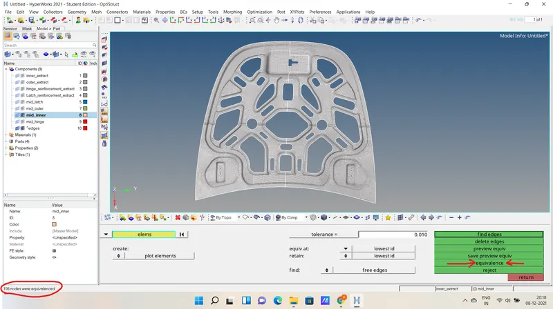
- Edges that had to be maually removed by replacing nodes.
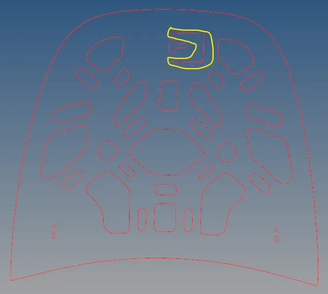
- Another small edge formed that had to be manually removed.
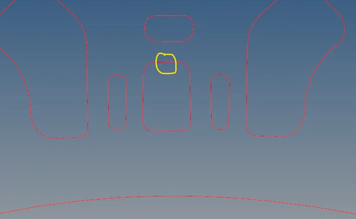
- Many things were tried on this edge but it got removed after we deleted one element and created a new element.
Result and final model:
- After everything was done we checked the geometry in 2d detailed element representation to check its thickness.