Week 9-Creation of 1D Connectors Challenge
Week 9 - Creation of 1D Connectors
OBJECTIVE
The aim of this challenge is to mesh the component with the target element size of 5 mm and to connect the different components using 1D connectors.
CAD MODEL IMAGE
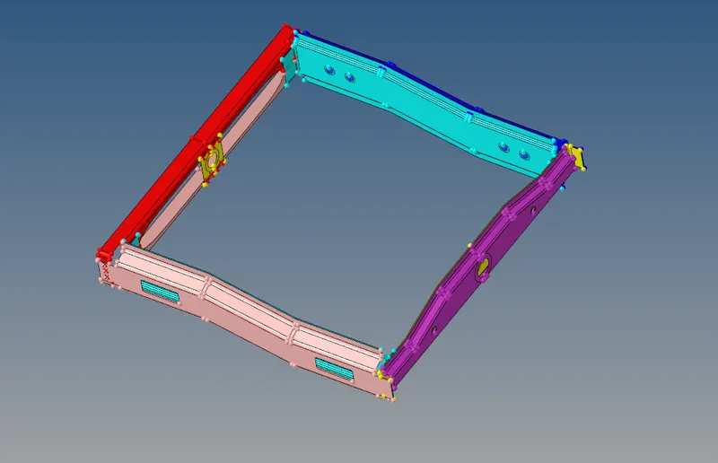
Fig, represents the CAD model image frame assembly
PROCEDURE
- The given model is imported using , import geometry option.
- After that ,the given components are meshed with the target element size of 5mm.
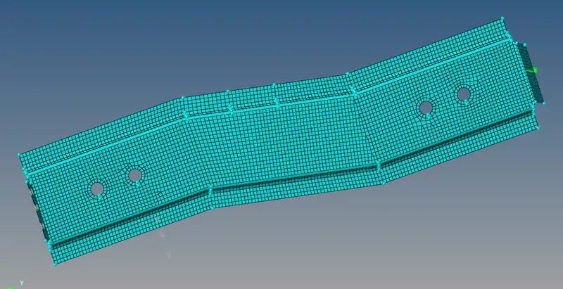
Fig,represents the meshing of a right rail component with a target element size of 5mm
- The right_rail_2 and Front_truss_1 are welded together using , 2D ➡ connectors ➡ seam ➡seam-quad(angle+capped+L) option.
- The parameters, such as spacing value, type of weld, and tolerance are given and the seam-quad(angle+capped+L) weld is created between Right_rail_2& Front_truss_1
Fig, represents the seam-quad(angle+capped+L) weld done for right_rail_2 &Front_truss1
- The Left_Rail_2 & Front_truss_1 are welded together, by using 2D ➡ seam ➡ quad elements option
- The parameters, such as spacing value, type of weld, and tolerance are given and the quad weld is created between Left_Rail_2 & Front_truss_1.
Fig, represents the quad, weld done for Left_Rail_2 & Front_truss_1
- The Front_truss_1, Front _ truss _2, and Right_rail_1 are welded together using 2D ➡ connectors ➡ spot weld option.
- The spot weld is done, with 3 layers and 5 mm diameter.
Fig, represents the spot weld done between, Front_truss_1 , Front _ truss _2 and Right_rail_1
- The Rear_truss_2 & Right _Rail_2 are connected together using 2D ➡ connectors ➡ bolt option.
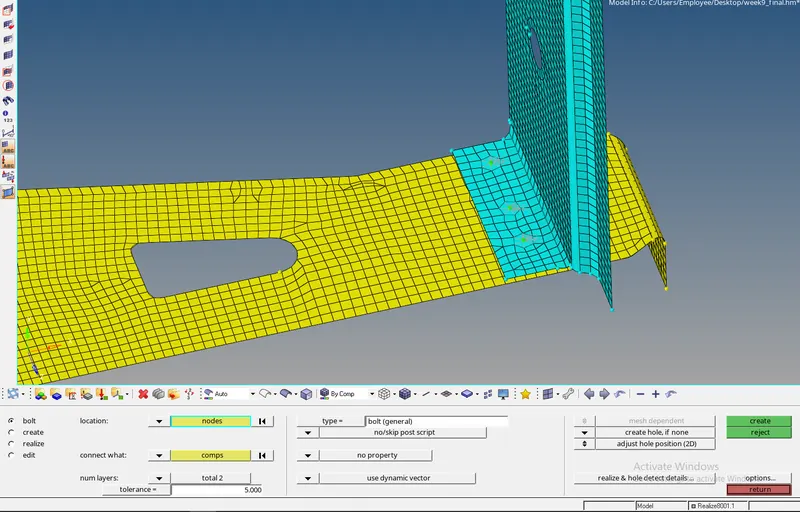
Fig, represents the Rear truss 2 & right rail 2 , connected together using bolt connector
- The Rear_truss_2 & left_Rail_2 are connected together using 2D ➡ connectors ➡ bolt option.
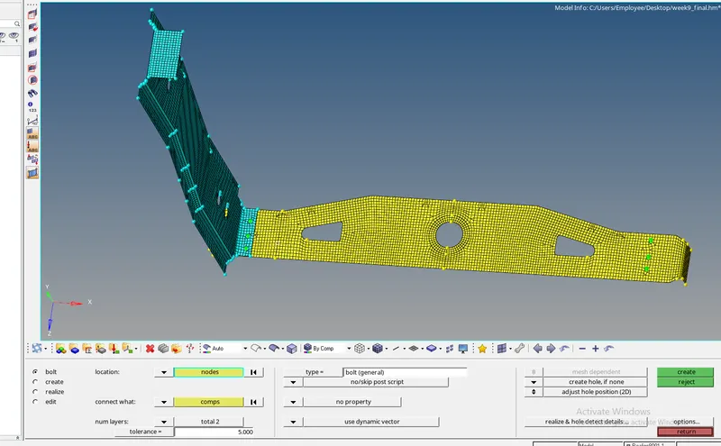
Fig, represents the Rear _truss _2 & left _rail _2, connected together using bolt connector
- The Right_rail_1 & right_Rail_2 are connected together using 2D ➡ connectors ➡ spot option
- In the spot weld type , rigid elements is selected and the components are joined together.
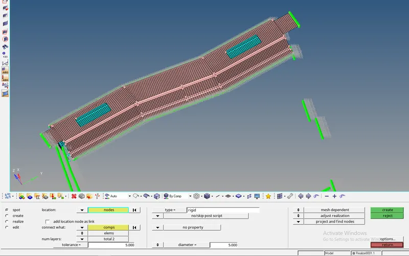
Fig, represents the Right_rail _1 & right _rail _2, connected together using spot _weld with rigid elements.
- The Left_rail_1 & Left_Rail_2 are connected together using 2D ➡ connectors ➡ spot option.
- In the spot weld type , the spring element is selected and the components are joined together.
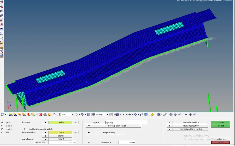
Fig, represents the Left_rail _1 & left _rail _2, connected together using spot _weld with spring elements.
- In general, while connecting or welding the two components, the nodes are checked for realization during the welding and once , the nodes are realized, the components are welded.
- Once the welding is done, the elements are checked for duplication and to check that the elements are masked using the F5 option and if the duplicate elements were present, the elements are selected by using the face option and the duplicate elements are deleted.
- The remaining components such as con_Fit _truss, con_Rear _truss, and Reinf_plate are meshed with the target element size of 5mm.
- Once the necessary connections are done, the rest of the components are joined by using spot weld.
RESULTS
Thus, the components are meshed with the target element size of 5 mm and the connections are deployed in accordance with the given connection details.
FINAL MODEL IMAGE
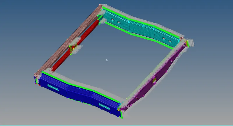
Fig, represents the connections deployed to all the components
LEARNING OUTCOMES
- Learned, what are connectors and why we need them.
- Learned, different types of connectors and their applications
- Learned about how to give tolerance and how to make the nodes realize while connecting to the component.
- Learned about realized connectors, unrealized connectors, and failed connectors
- Learned about different types of weld angles.