Week 8-3D Tetra Meshing Challenge
Report-8
OBJECTIVE
The aim of this challenge is to generate 3D tetra mesh for the given models, with the below-mentioned quality criteria.
Quality criteria
Model-1 (housing)
Target element size =5
Min element size=2
Max element size =7
Tet collapse=0.15
Model - 2 & 3 (crank housing & axle)
Target element size =6
Min element size=2
Max element size =7
Tet collapse=0.15
CAD MODEL IMAGE
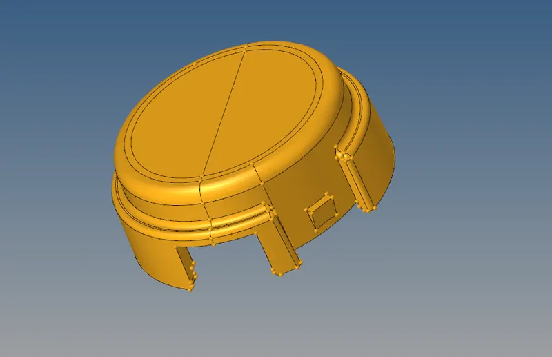
Fig, represents the housing component
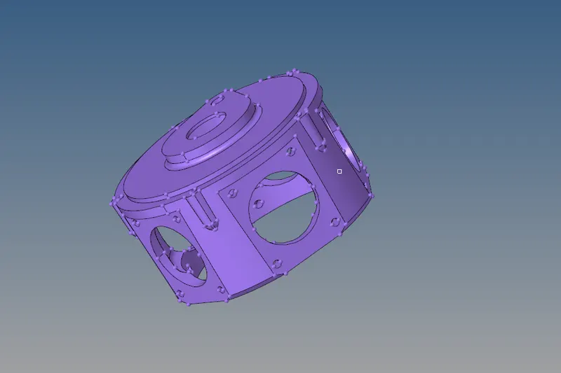
Fig, represents the crank housing
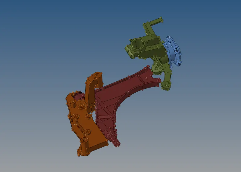
Fig, represents the axle components
PROCEDURE
- The given model is imported using, import geometry option.
- After, importing the geometry is defeatured according to the min element size. and unwanted lines such as free edges and T edges are removed.
- After that, by using the utility option quick tetra mesh is performed by selecting the component.
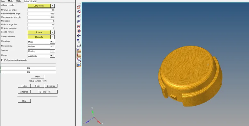
Fig, represents the meshing of a housing component using quick tetra mesh
- In order to ensure the capturing of tetra elements, the elements are selected and masked to see the tetra elements.
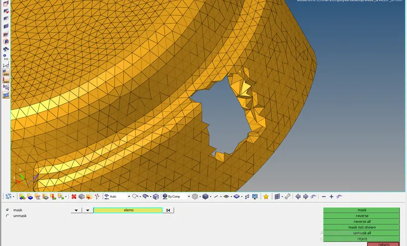
- The quality such as tet collapse for 0.15 mm is checked for the given model to ensure the quality.
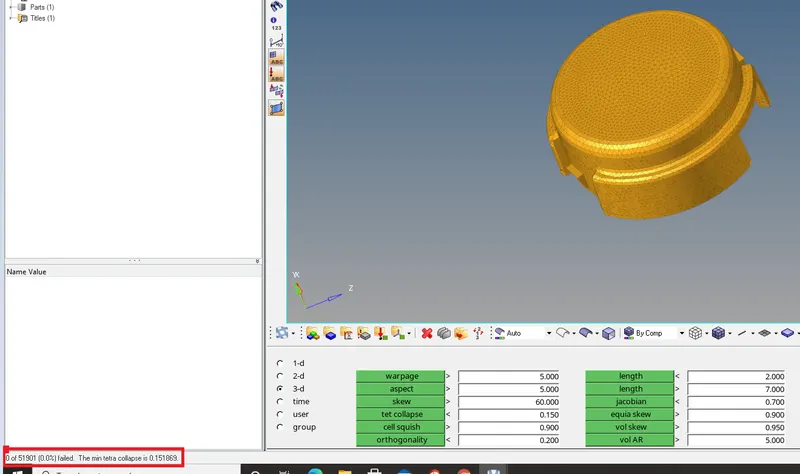
Fig, represents the quality check (tet collapse ) for the housing model
- In a similar fashion, the other component is meshed and checked for tet collapse.
- In a similar fashion, model 2 has been meshed with the same method and it's checked for tet collapse.
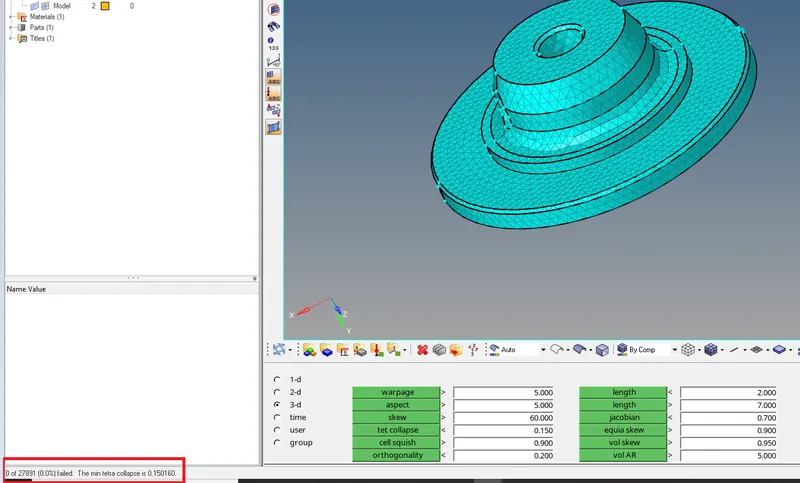
- In a similar fashion, model 2 has meshed with the same method and it's checked for tet collapse.
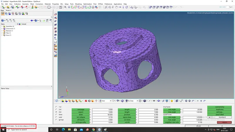
- For the axle assembly, the model is imported and defeaturing is done for each individual component.
- The surf fillets are defeatured with the respect to the min element size of 2 mm
- The unwanted lines and some features were defeatured to avoid the failure of elements.
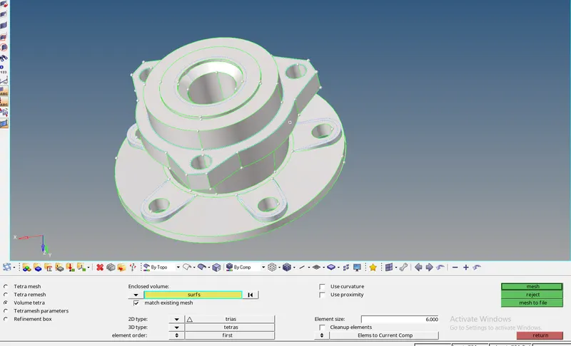 Fig. represents the defeature of the component
- The hub teeth are removed and the surface edges are joined together.
- Once, the defeaturing is done, the component is meshed using volume tetra mesh by using the surface option.
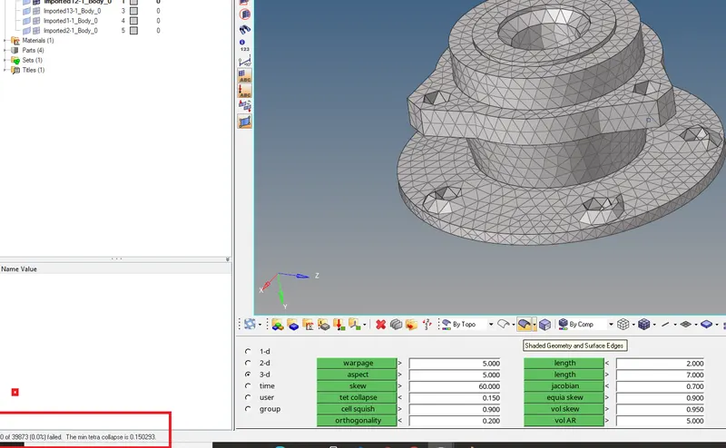
- Before, tetra mesh parameters such as min tetra, max tetra, and tet collapse value are given in the tetra mesh parameters.
- After that, by using volume tetra and by selecting the surface, the component is meshed for tetra meshing.
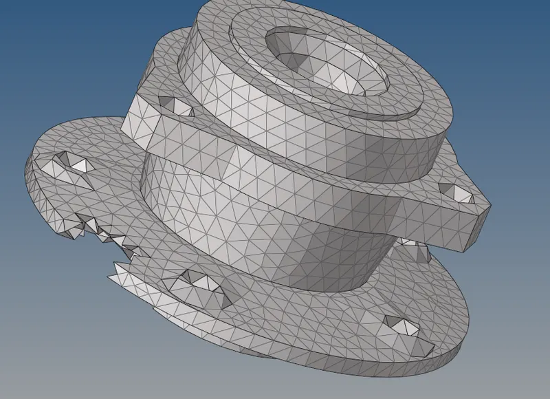
- In order to ensure the capturing of tetra elements, the elements are selected and masked to see the 3D tetra element.
- Finally, the component is checked for tet collapse.
- The elements which were failing for tet collapse were fixed by using the tetra remesh option and by increasing the height of tetra elements using the distance option (F4).
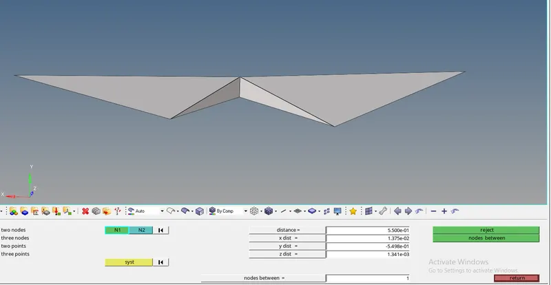
- In a similar fashion or method, the other components are meshed using, volume tetra option.
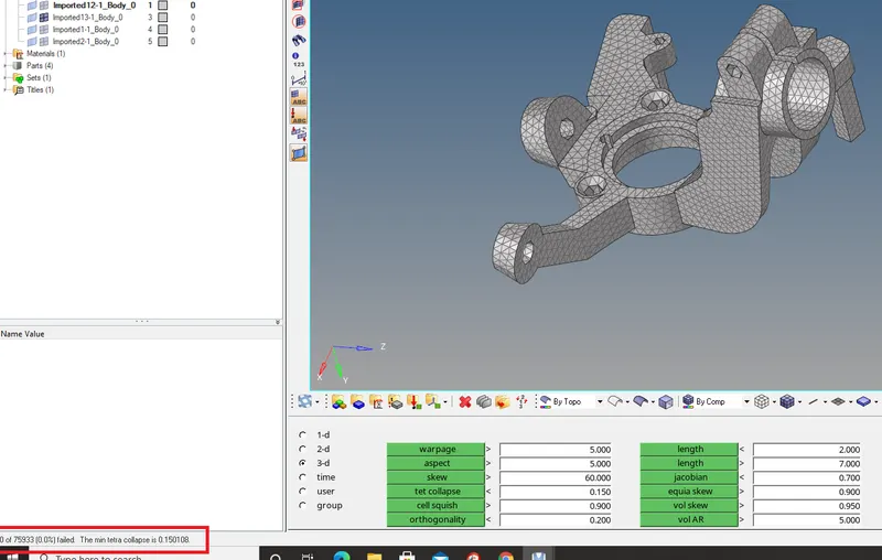
Fig, represents a component, checked for the tet collapse
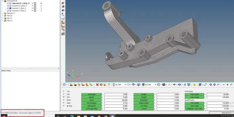
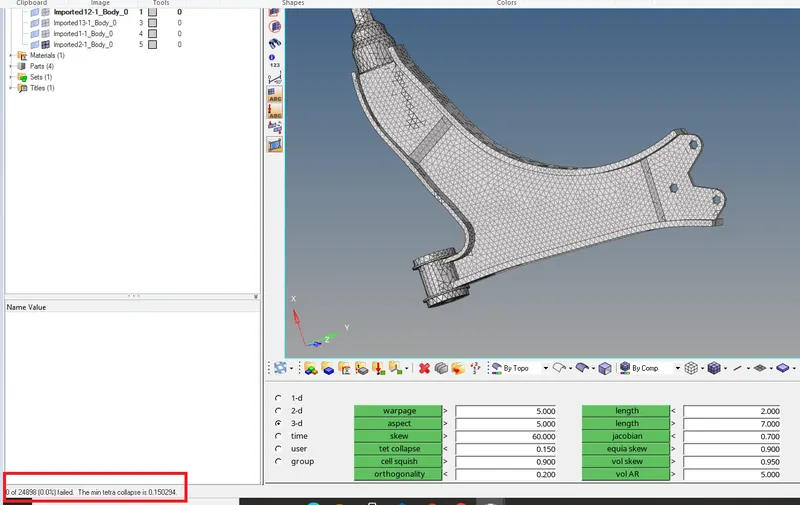
- Finally, the components are checked for the tet collapse to ensure, whether the tetra elements are failed.
RESULTS
Thus, the given models are meshed with given quality criteria and the tet collapse is successfully checked for each model.
FINAL MODEL IMAGE
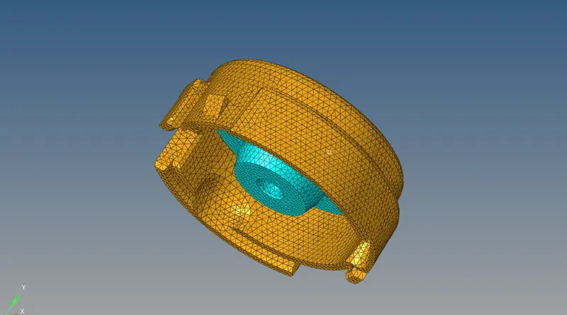
Fig, represents the final model image of the housing model
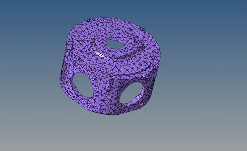
Fig, represents the final model image of the crank housing
Fig, represents the final model image of the axle assembly
LEARNING OUTCOMES
- Learned about the usage of 3D tetra elements and Hexa elements in the industry.
- Learned about the different approaches of 3D meshing such as 3D tetra mesh by direct component, volume tetra mesh, conversion of 2D tria elements to 3D elements by using the surface option method.
- Learned about tetra remesh and tet collapse (quality checks)
- Learned about the meshing of Hexa elements.