Week 4- Challenge
Report 3
Objective:
The aim of this report is used to create the various 1D elements such as Rod, beam, and bar elements in the given parallel bracket and to generate the mesh, by giving various cross-sections such as Box, I section, and cross-section and assigning the property to them. The links such as RBE2 and RBE3 are given to1D elements with the given set of DOF’S. The mass of magnitude 10 is created using the RBE2 link at both the circular area d and e respectively. Finally, the two components are joined with the help of spring elements.
CAD MODEL IMAGE:
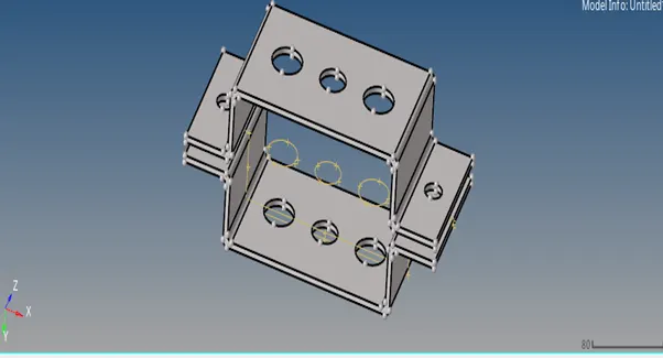
Fig, represents the CAD model image of the parallel bracket
PROCEDURE:
- The parallel bracket model is imported using the import option present in the import.
- Then, in the geometry, we go to the mid surface option and we select one surface on the upper part and the midsurface is extracted for the upper bracket.
- Midsurface (surface between two components) is the 2d representation of the 3D model and it is created to reduce the computational time and it is created with shell elements.
- Another component is created, to move the midsurface to the created component, since it’s a single component.
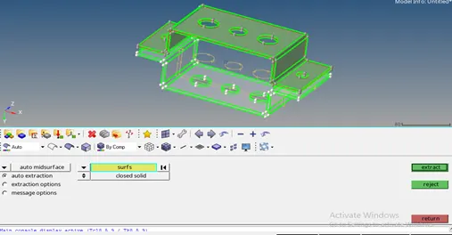
Fig, Represents the extraction of midsurface
- After that, the solid component is deleted to visualize the extracted midsurface.
- The midsurface is created at the bottom bracket by clicking on the bottom surface.
- After that, in the organize menu the bottom bracket surface is selected and the midsurface is moved to component and after that, the midsurface is deleted.
- Then, the material steel is created and assigned for both the brackets, and then the properties are assigned to both the brackets, and the thickness of 2.0mm and 2.5 mm are assigned respectively.
- Additionally, the Pshell elements and material are assigned for both the brackets.
- Similarly, the material (steel) is assigned for the two components which are bracket 1 and bracket 2 respectively.
- Then, a washer split of 5 mm is created to capture the mesh in and around the circular area.
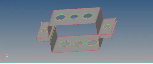
Fig. shows the creation of a 5mm washer split
- After, that the mesh (element size =4mm) is created by selecting all the surfaces using mixed element type.
- The number of nodes at the inner circular area is adjusted to the outer circular area (washer split).
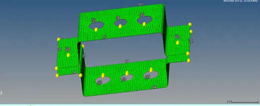
Fig: Represents the automesh of the bracket
- Then, rigids element is selected and the circular area with the label a is selected and the node is created by clicking at the centre. The multiple nodes option is selected and by path is given around the circular area. The multiples nodes are formed both on the upper and lower bracket.
- The translational DOF is selected with only one DOF and by clicking the nodes in the parallel brackets RBE2 link is created.
- The various link such as RBE2 for rod element with 1DOF’S, RBE3 link with all DOF for beam element, and RBE3 link for bar element with only x and y DOF are created.
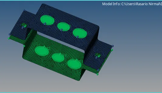
Fig. Represents the various link elements for rod, Beam, and bar.
- Then, the cross-section such as box, I section, and cross-section are created for rod, beam, and bar respectively.
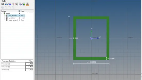
Fig. Represents the creation of various cross-sections
- The dimensions for the box, I section, and cross-section are assigned and created successfully.
- Then the properties for the rod, beam, and bar element are created.
- Furthermore, in the properties, the cross-sections for the rod, beam, and bar elements are assigned and the card image such as PROD, PBEAM, and PBAR is assigned successfully.
- Additionally, the properties of the rod, beam, and bar element are updated by assigning the property and updated for each 1D element.
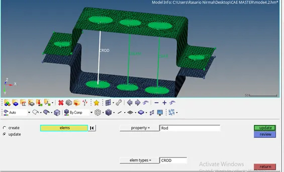
Fig. Represents the selection of property and updating the CROD
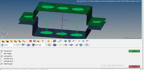
Fig. Represents updating, the property for CBEAM
- Similarly, beam and bar element is selected, their property is assigned and updated successfully.
- After, updating the elements, the visualization of the various cross-sections can be done by selecting the 1D detailed element representation.
- Furthermore, an RBE2 LINK is created on the circular areas d and e respectively and CMASS of 10 is applied to both the RBE2 links.
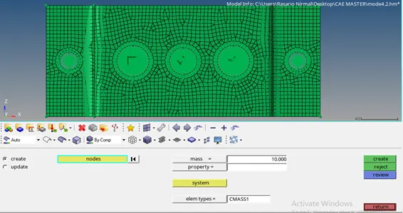
Fig.Represents the creation of RBE2 link and applying of mass on the links
- Finally, a spring element is selected, and the nodes are created on the upper and lower bracket and the two components are joined together with the help of the spring element.
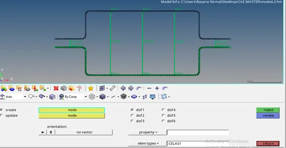
Fig, Represents the Spring element created on the circular areas of d & e
Results
- Thus, the 1D elements are created on the given component and the various cross-sections and different DOF are given to each element under the given conditions.
- The cross-sections are created and assigned with different dimensions for each element successfully.
- The properties for different elements are created and the cross-sections are assigned successfully for each element.
- The visualization for the cross-section of rod, beam, and bar is viewed successfully.
- A mass of 10 is applied on both RBE2 links (d & e) successfully.
- Finally, the two components are joined successfully by deploying the spring elements.
Final Model Image
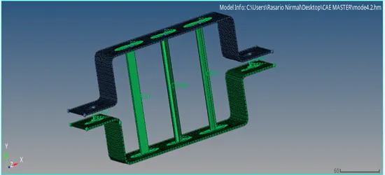
Fig, represents the final model image of the component