Week 12:Project 2-Meshing of Rear Wheel Holder challenge
Project 2 - Meshing of a Rear-Wheel holder
OBJECTIVE
The aim of this project is to generate the mid surface and to generate the mesh on the given component in accordance with the given quality criteria and assign a thickness to it.
CAD MODEL IMAGE
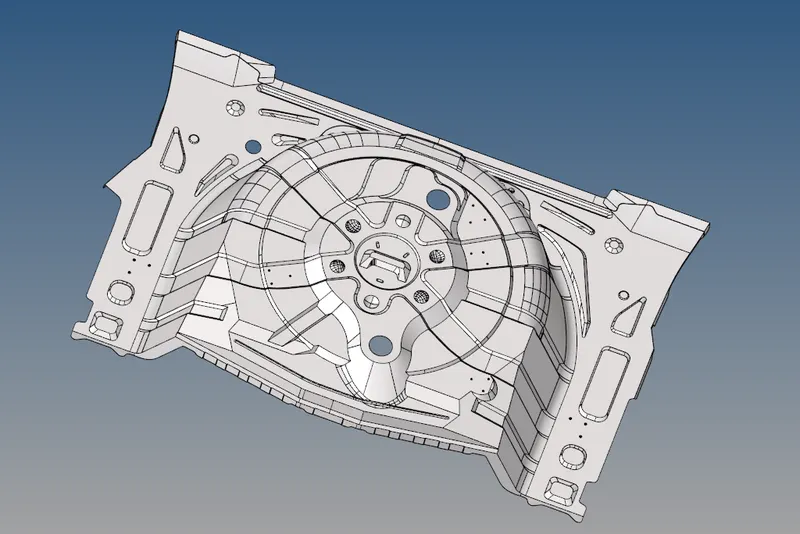
Fig, represents the CAD model image of a side door panel
PROCEDURE
- The given CAD model is imported using the import option.
- Then, the component is visually checked to confirm whether it's a plastic or sheet metal component.
- The thickness of the component is measured using the F4 ( distance ) option.
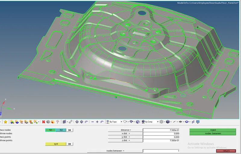
Fig, represents the thickness measurement on the edge
- Since every feature has a uniform thickness, it is confirmed that the given component is a sheet metal.
- Then , the midsurface is generated to the component by measuring the thickness of the component.
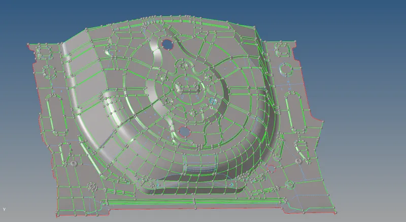
Fig, represents the generated mid surface of the rear wheel holder
- After, manual mid-surfacing is done the geometrical clean-up is done for the entire component.
- Some unwanted lines and free edges inside the component are fixed by using the equivalence option.
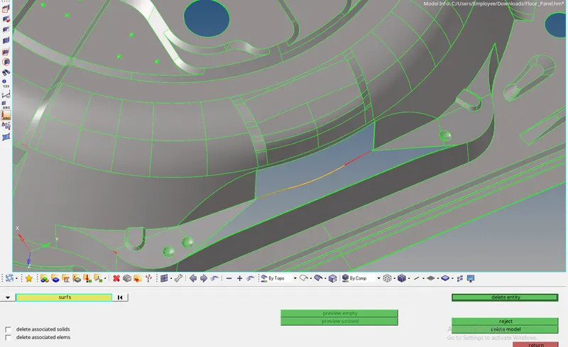
Fig, represents the geometry clean up and deletion of the unwanted surfaces which is forming T- edges
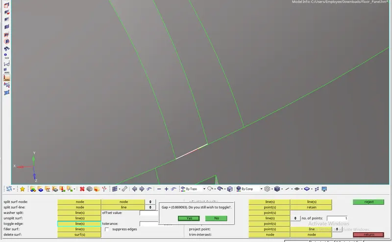
Fig, represents the equivalence of free edges by using the toggle option
- The free edges and T edges present inside the components are equivalenced by using the toggle option respectively.
- The button-like and spherical features are deleted since we expect that would disturb the mesh flow inside the component.
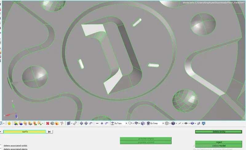
Fig, represents the deletion of the button-like surfaces
- Before meshing, the entire component is splitted into various segments in order to get the proper mesh flow.
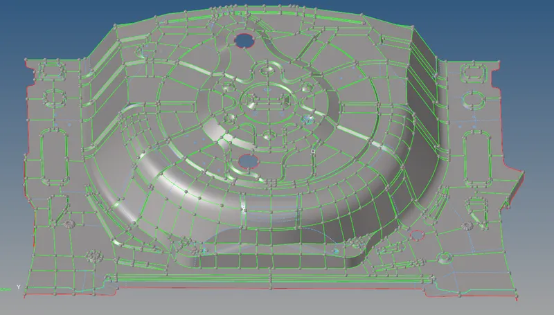
Fig, represents the overall view of a split that has been made in the component
- Then, the entire component is meshed with the target element length of 5 mm.
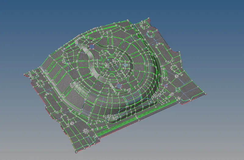
Fig, represents the meshing of the entire rear wheel holder
- Then, the quality errors such as warpage, max angle quad, min, and max size are fixed by using options such as element optimize, translate, and distance option respectively.
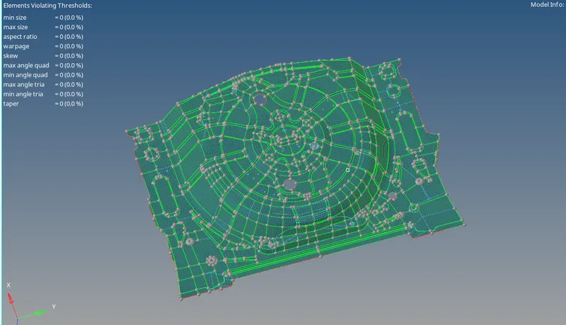
Fig, represents the final quality check for the rear wheel holder
- The final quality check is done to ensure that the entire component is meshed according to the given quality criteria.
- Finally, the free edges are checked for the component.
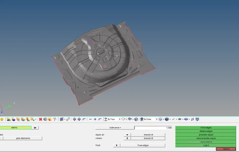
Fig, represents the checking of free edges present in the component.
- It has been observed that the given component has successfully passed the quality criteria with zero errors.
- After the meshing is done in the component, the thickness is measured and the component is created for the component along with the property.
- The property( thickness) is assigned to the component, and the elements are organized in the created component.
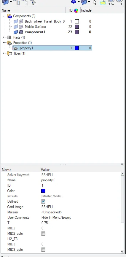
Fig, represents the creation of component and assigning of properties for the component
RESULTS
- Thus, the mid surface for the given component is generated successfully and meshed according to the given quality criteria.
FINAL MODEL IMAGE
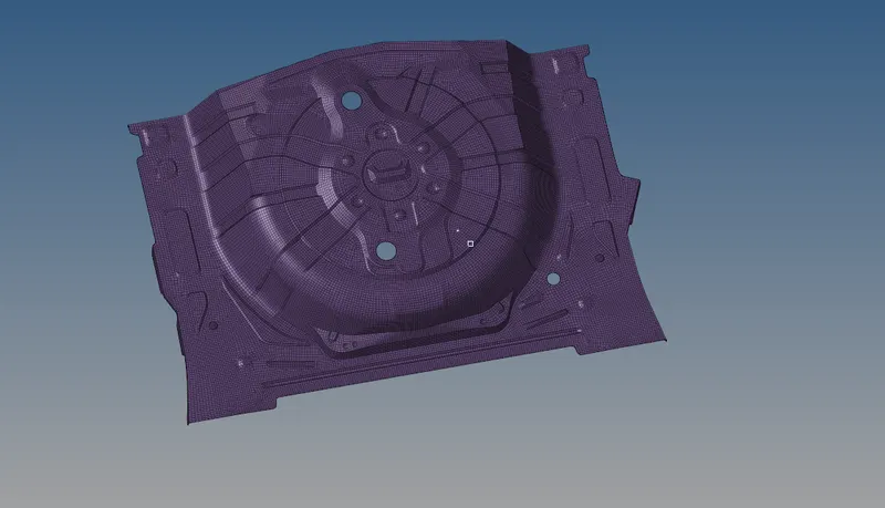
Fig, represents the final model image of a rear-wheel holder