Week 6- Challenge
WEEK 6 – CHALLENGE
OBJECTIVE
The aim of this challenge is to generate the midsurface for the each given components of the hood (plastic component) and the mesh it with the below mentioned quality criteria.
QUALITY CRITERIA
Target Element Length = 5mm
|
S.N |
Quality Criteria |
Value |
|
1 |
Aspect Ratio |
5 |
|
2 |
Skewness |
45 |
|
3 |
Warping |
15 |
|
4 |
Taper |
0.5 |
|
5 |
Min. Length |
2mm |
|
6 |
Max. Length |
8mm |
|
7 |
Min angle Quad |
45 |
|
8 |
Max angle Quad |
135 |
|
9 |
Min angle Tria |
20 |
|
10 |
Max angle Tria |
120 |
|
10 |
Tria % |
10 |
CAD MODEL
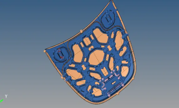
Fig. shows the representation of hood model
PROCEDURE
General steps
- Import
- Deleting the solid surfaces
- Geometry clean up
- Midsurface extraction
- Defeaturing and rearrangement
- Assigning the quality criteria
- Meshing
- Quality check
BRIEF EXPLANATION
- The given hood model is imported using the import option.
- The hood consists of different components such as inner panel, outer panel, hinge and latch.
- Since, we are dealing with the plastic components, the solid part of the model is deleted.
- Then, the Midsurface is generated for each individual component, in order to reduce the computational time of the solid model .
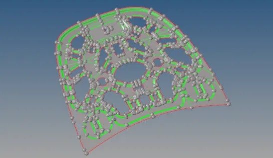
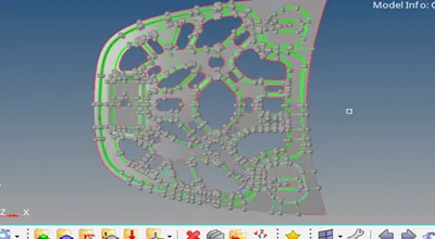
Midsurface of the inner panel
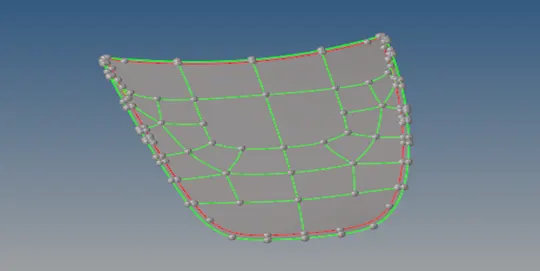
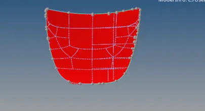
Midsurface of the outer panel
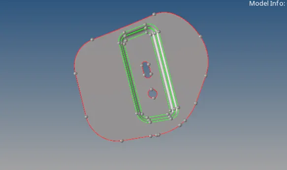
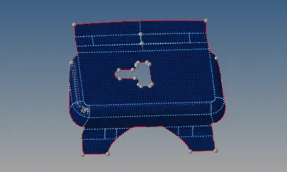
Midsurface of the hinge
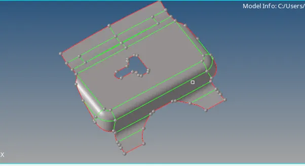
Midsurface of latch
- After, generating the midsurface, the geometrical clean-up is done to remove the unwanted shared edges which fails for min length.
- The vertical and the horizontal lines are toggled up using toggle option and the rearrangement is done to achieve the proper mesh flow in the flat and in the fillet regions.
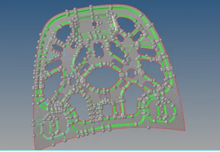
Fig. shows the geometry clean up of the inner panel
- The areas of the fillet and the unwanted lines are toggled using the toggled option.
- The rearrangement of the lines is done at the fillet and the curve regions to provide the better mesh flow at those regions.
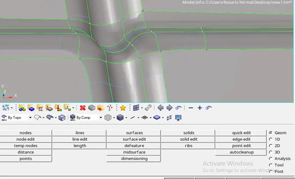
Fig. Represents the rearrangement of lines at the fillet regions
- The horizontal and vertical splits are done at the model to enhance the proper mesh flow in the model.
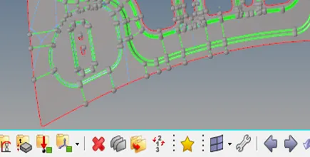
Fig. Represents the splitting of surface in the inner panel to enhance the mesh flow
- Once, the geometry clean-up is done the parameters are entered in the criteria file settings for setting up the quality parameters.
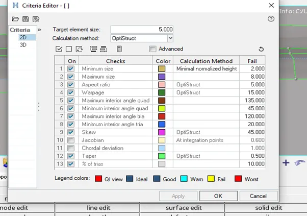
Fig. Represents the values that have been entered for quality criteria in the criteria file settings
- Once, everything is done the model is meshed with the target element size of 5mm in the model.
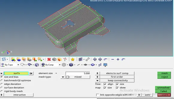
Fig. Represents the meshing of the latch with the target element size of 5mm
- The opposite trias are handled by using drag tria option present in the hypermesh.
- The back to back trias are also handled by using drag tria option.
- The maximum and the minimum size errors of the quad elements are handled using element optimize and place done option.
- Remeshing is also done to avoid these quality errors present in the model.
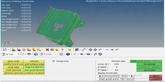
Fig. Represents the clean-up tool to fix quality errors.
- The same meshing procedure and the quality checks are done for the hinge, inner panel, and the outer panel respectively.
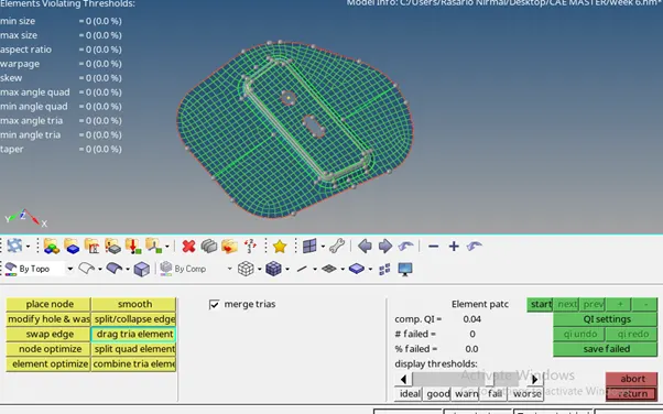
Fig. Meshing of the Hinge model
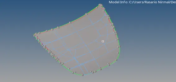
Fig. Represents the meshing of the outer panel
- The outer panel is meshed by splitting the panel with several splits to enhance the proper mesh flow.
- The outer panel is meshed on its one half and the elements are reflected using the reflect option.
- The reflect option is selected and the elements are duplicated and finally the base node is selected with Y axis and finally the reflection is done.
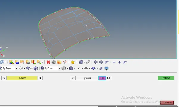
Fig. Represents the reflection of the elements in the outer panel
- In the similar fashion, the reflection is done for the inner panel.
- Once the meshing is done, the quality check-up is done by using F10 option.
- The quality parameters such as warpage, skew, max angle quad and the min angle quad are checked.
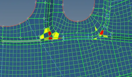
Fig. Represents the warpage error present on the inner panel
- Warpage error occurs due to the deviation of the node of an element from its original plane. The warpage angles are measured to remove the warpage error present in the model.
- The warpage error can be avoided either by remeshing of the area or by translating the node of the element using translate option.
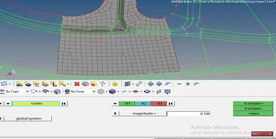
Fig. Represents the rectification of the warpage error present in the inner panel
- Once, the errors such as warpage, skewness, max angle quad and min angle quad are fixed. The model is checked for ensuring the free edges.
- The purpose of checking the free edges is to ensure whether there is nodal connectivity missing in the model.
- The nodes which are not connected are connected by checked by using find the free edges option and if the nodes are disconnected, the nodes are connected back by using the equivalence option.
- Finally, the model is checked for ensuring the free edges.
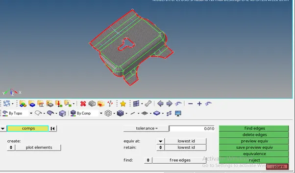
Fig. Represents the final checking of free edges present in the model.
- Thus, the hood model is meshed with above-mentioned quality parameters and the free edges of the model are checked successfully.
RESULTS
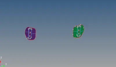
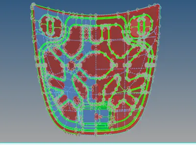
Thus, the midsurface for each component is generated and the mesh has been created for each individual component successfully as per the given quality criteria using the hypermesh.
FINAL MODEL IMAGE
CONCLUSION
Thus, in the above hood model, the midsurface is been extracted and then the model is meshed as per the given quality criteria successfully.