Week 12:Project 2-Meshing of Rear Wheel Holder challenge
AIM: -To create a mesh on a Spare wheel Holderby performing a geometric clean-up and assigning thickness property to all the meshed elements.
OBJECTIVE: -
- Import the model and organise the components.
- Creating a criteria file.
- Creating a duplicate component and organise the surface.
- Extraction of mid surface from the duplicate component.
- Reference with parent the surface created will be checked.
- Missing surface is created by using offset from parent component.
- Selecting the surfaces with similar shape individual.
- Creating a mid-surface using final edit tools from midsurface panel.
- Checking of the midsurface and providing cut lines to have proper mesh flow.
- Creating section of the components into mesh region.
- Check for trias and rotational quads.
- Elimination of trias by rebuild mesh and automesh.
- Performing quality index operation drag trias out and smoothing the dragged area.
- Check for element quality criteria and fix them by projecting the node for warpage and element for skew, min and Max length.
- Check for free edges and equivalence
- Creating property and adding thickness to the mesh.
- Detailed 2d view updating and assigning thickness.
- Check for Tria percentage.
THEORETICAL EXPLAINATION: -
- Spare wheel is or spare tire is an additional tire carried in a car or any automobile as a replacement for one that tire goes flat or blowout or has another emergency. A Spare wheel is a additional and safety feature in a car, were the location of the spare wheel changes from the type of the car i.e. on road cars will have in the trunk bed. For an off-roading car its mounted on the rear bumper attachment as shown in fig 1.1.
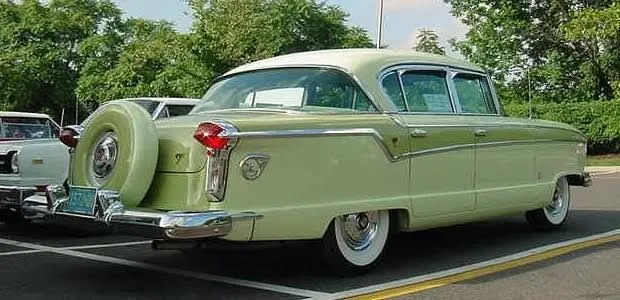
fig 1.1
- Spare tires in automobiles are often stored in a spare tire well – a recessed area in the trunk of a vehicle, usually in the center, where the spare tire is stored while not in use. In most cars, the spare tire is secured with a bolt and wing-nut style fastener. Usually, a stiff sheet of cardboard lies on top of the spare tire well with the trunk carpet on top of it to hide the spare tire and provide a pleasant look to and a flat surface for the trunk space as shown in fig 1.2.
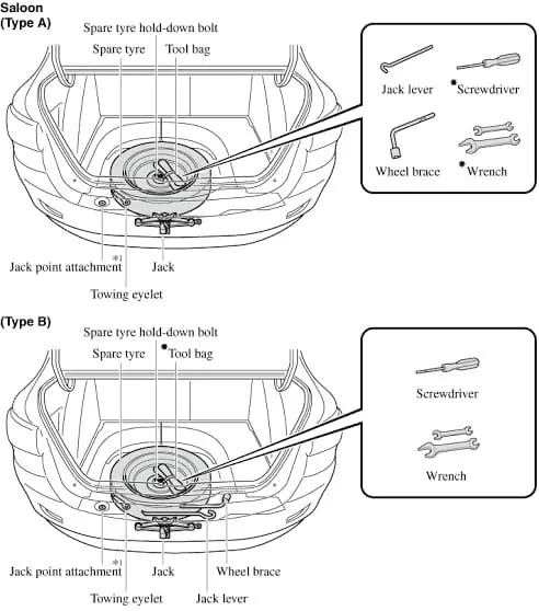
fig 1.2
- Automakers often equipped cars with one or dual side mounts. The spares were mounted behind the front fenders as they blended into the running boards (a narrow footboard serving as a step beneath the doors).Other storage locations include a cradle underneath the rear of the vehicle. This cradle is usually secured by a bolt that is accessible from inside the trunk, for security. This arrangement has advantages over storing the tire inside the trunk, including not having to empty the contents of the trunk to access the wheel and this arrangement may also save space in some applications as shown in fig 1.3.

fig 1.3
- However, it has disadvantages because that tire gets dirty, making the act of changing the tire more unpleasant and the mechanism may also rust on older cars, making it difficult to free the spare. The cradle arrangement is usually only practical on front wheel drive cars, as the cradle would get in the way of the rear axle on most rear or four-wheel drive cars. A similar arrangement is also often found on trucks where the spare is often stored beneath the truck bed as shown in fig 1.4.
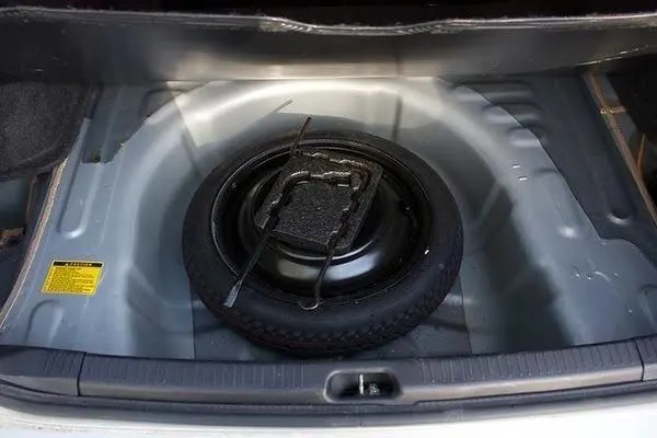
fig 1.4
- Many sport utility vehicles (SUVs) and off-road vehicles have the spare wheel mounted externally – usually on the rear door, but others may mount them on the roof, the side, or even on the bonnet (hood) as shown in fig 1.5.
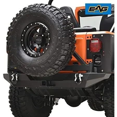
fig 1.5
PROCEDURE:-
* The criteria file setting is updated as per as the mentioned in the task, The values are updated and set as mentioned as shown in fig 1.6
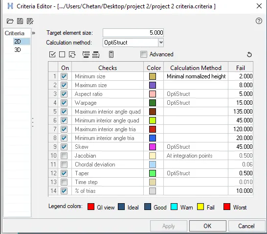
fig1.6
*The import of the model is been done by Model components for the Side door panel as shown in fig1.7.
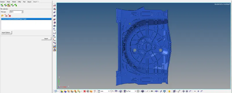
fig 1.7
*The Duplicate is created and the component is organised and the component is copied as shown in fig 1.8.
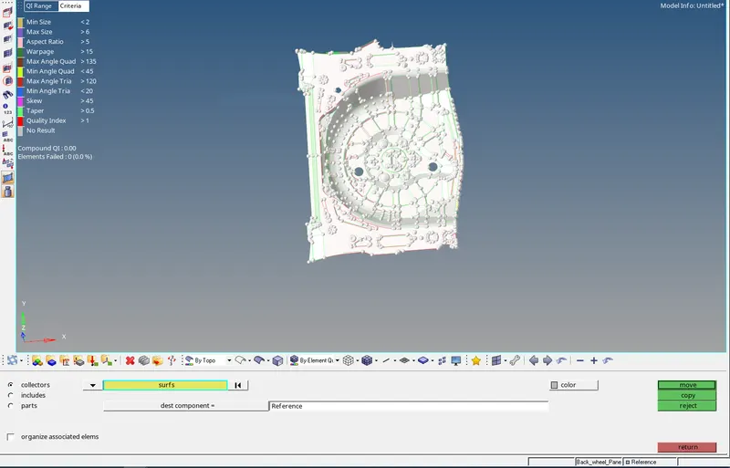
fig1.8
*The mid surface is extracted for Spare wheel Holder the component by using skin offset as shown in fig 1.9.
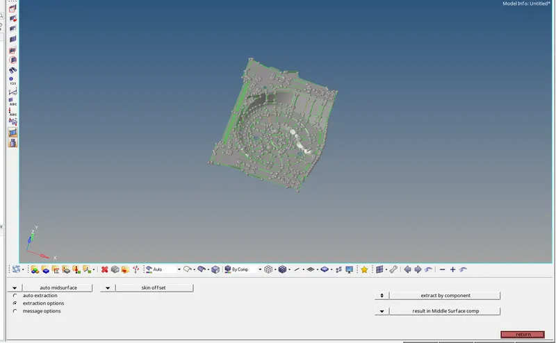
fig1.9
* The Missing surface is created by using offset from parent component by selecting the surfaces with similar shape individually as shown in fig 1.10.
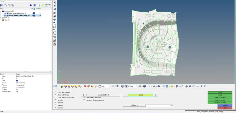
fig1.10
*The Spare wheel Holder mid surface geometrical clean-up is done by toggle line of unwanted lines and regions as shown in fig 1.11.
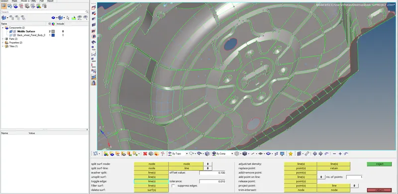
fig1.11
*In damage areas the surface is created using ruled options to create surface as shown in fig 1.12.
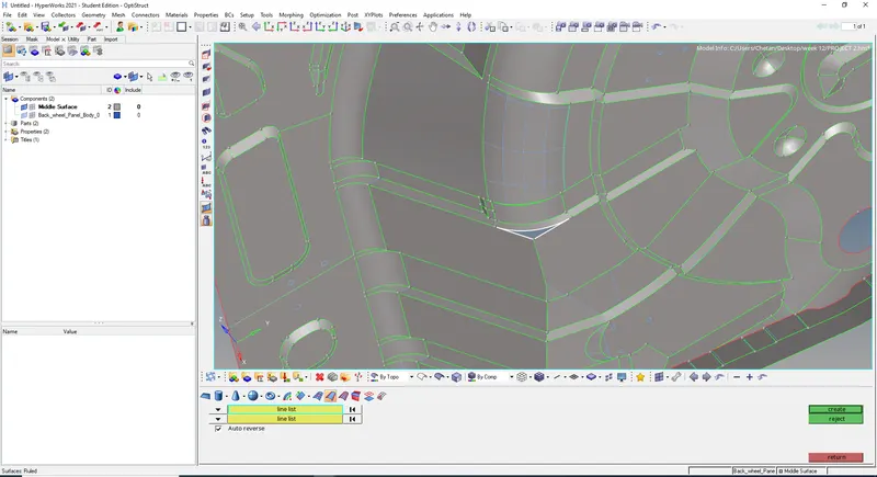
fig1.12
*In the process of mid surface creations duplicate surface are created by using delete this can be eliminated as shown in fig 1.13.
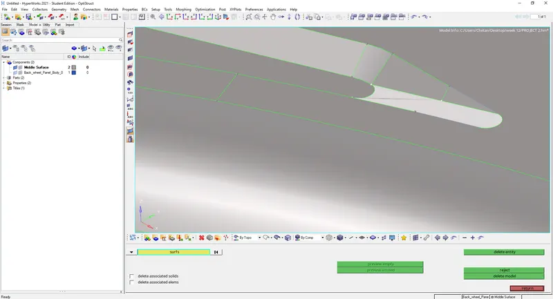
fig 1.13
*The Mid surface is created for meshing and unwanted line and fillets are toggled and sections are created for proper mesh creation as shown in fig 1.14.
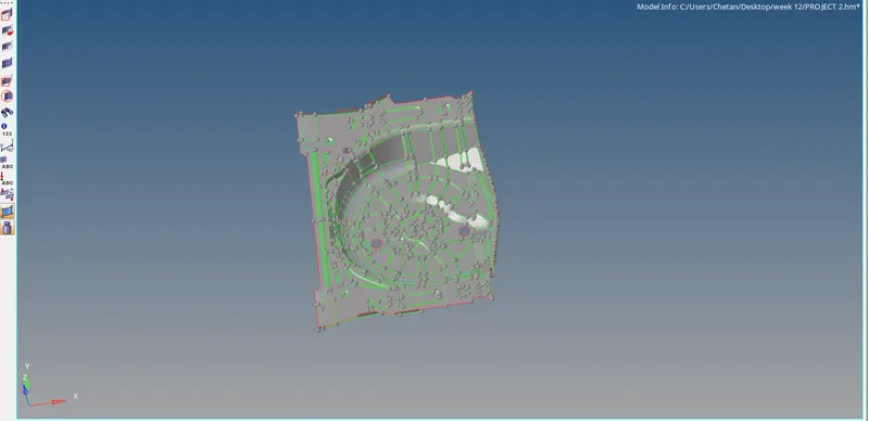
fig1.14
*The meshing is done by selecting surfaces individually so the mesh would be uniform and good mesh flow as shown in fig 1.15.
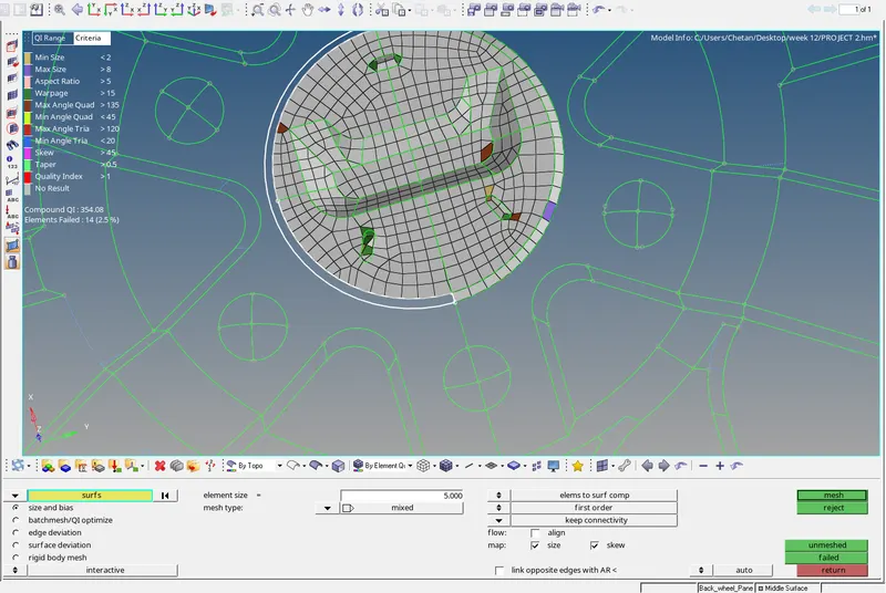
fig1.15
*By using quality index, the trias elements are dragged out the component in their direction as shown in fig 1.16.
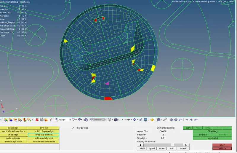
fig1.16
*After dragging the tria element the elements are selected in defined geometry and smooth operation is used by keep nodes on geometry edges and smooth is done as shown in fig 1.17.
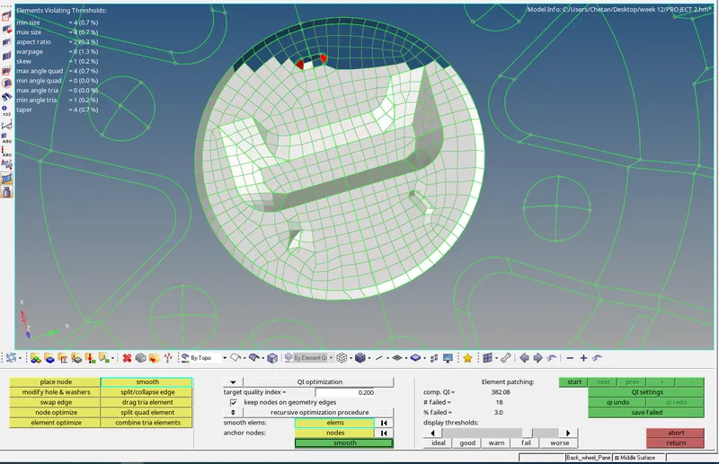
fig1.17
*Failed elements are selected and smooth operation is used to fix the issue, element optimize is also used as shown in fig 1.18.
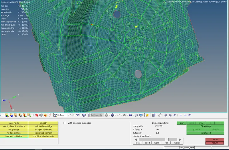
fig1.18
* By using translate option the warpage in the element is removed this works under only 10 degree of excess, the nodes are selected and a magnitude of 0.1 is used as shown in fig 1.19.
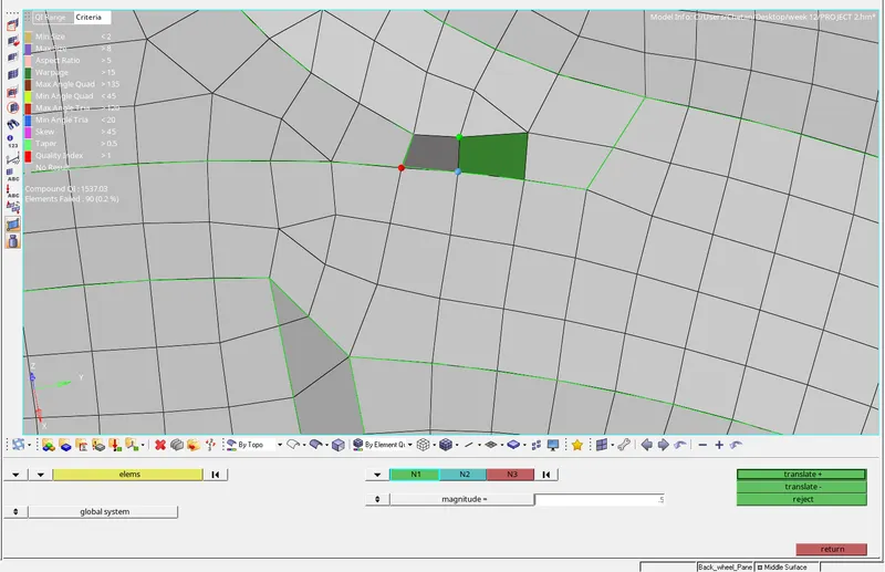
fig 1.19
*For such areas the nodes are projected on the line so the mesh flow and the geometry capture will be achieved as shown in fig 1.20.
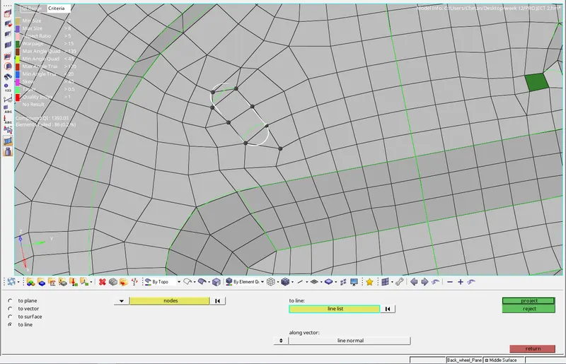
fig 1.20
*The minimun length fail is rectified by using distance option and by selecting the node the dimention is changed with out harming the geometry as shown in fig 1.21.
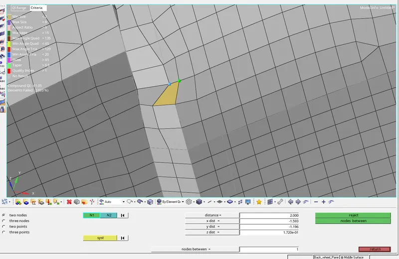
fig 1.21
*The elements failing for quality criteria the elements can be saved from quality index and save failed by using mask option the elements failed can be retrieved and fix the failed elements as shown in fig 1.22.
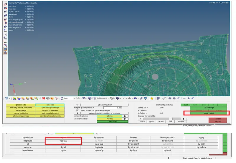
fig 1.22
*The overall tria percentage was checked the value was 2.4 % and no elements were failing for quality criteria as shown in fig 1.23.
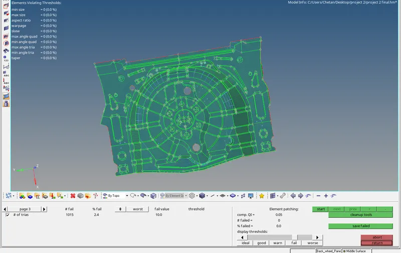
fig1.23
*The free edges are checked if any openings or error in the surface by selecting the component, red lines indicate the free edges as shown in fig 1.24.
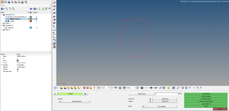
fig1.24
*Creating the Property and in the property cards defining the thickness value for the mesh as shown in fig 1.25.
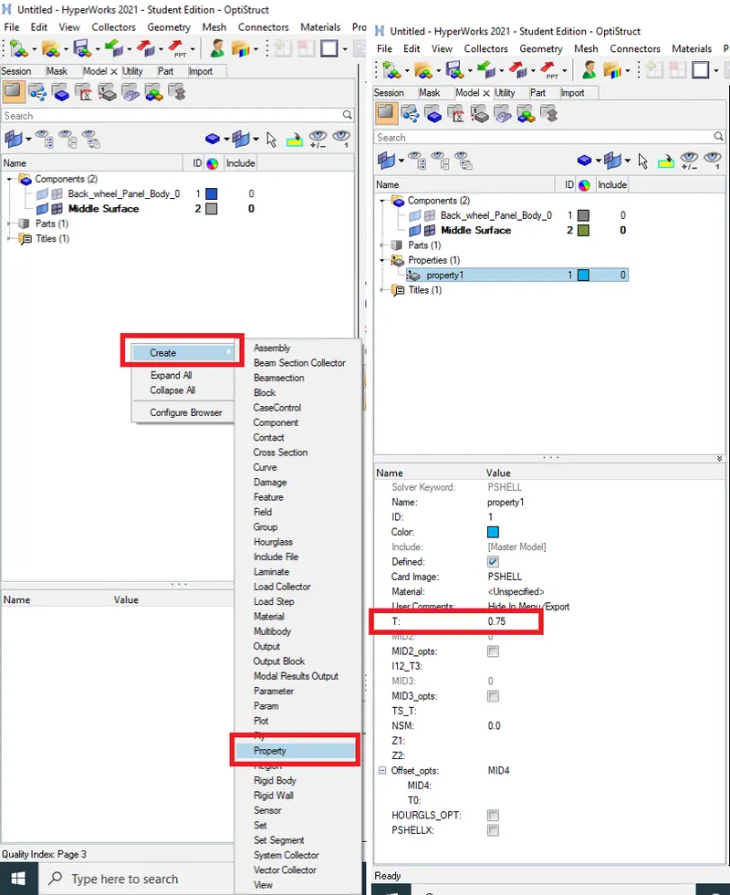
fig 1.25
* Selecting the Spare wheel Holder components and assigning the material and property details as shown in fig 1.26.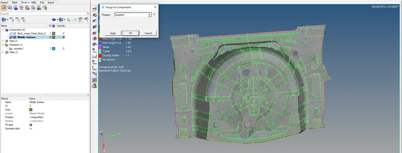
fig 1.26
* By using the 2D Detailed element representation we can view the different cross-sectional elements in assigned thickness, this can be used as checker for and error due to updating the Element Type as shown in fig 1.27.
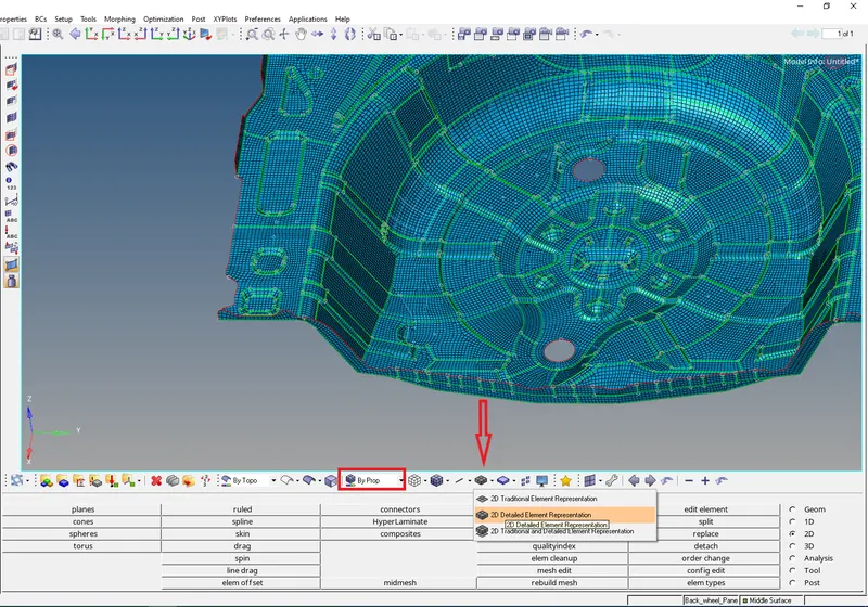
fig 1.27
*The final model is achieved as per as the specified the Spare wheel Holder components are positioned in front view as shown in fig 1.28.
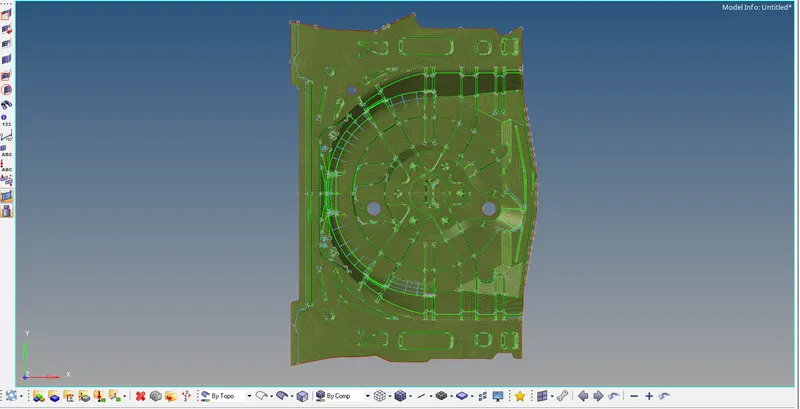
fig 1.28
RESULT:- The Spare wheel Holder model has been extraction of mid surface to mesh the model with overall tria percentage is been found to be 2.4% and the components are not failing for quality criteria. The free edges were checked with assigning property to the component represented in Front view.