Application of connectors in Hypermesh
Week 9 Challenge
AIM: Create different connectors and attached the given components in an assembly using Hypermesh.
BRIEF: Connectors are the geometric entities, which are primarily used to represent the CAD geometric connections in terms of FEA. Connections can be created as a spot-weld, seam weld, adhesive, bolts and masses. A realized connectors will be considered as the successful representation of a CAD model in preprocessing and the connecting parts can be considered as connected.
There are 3 states of connectors
- Realize: They are the successful connection between two components and represented in green colour.
- Unrealize: They are the successful connection between two components and represented in yellow colour.
- Failed: hey are the failed connection between two components and represented in red colour.
PROCEDURE:
Step 1: Import the import model.
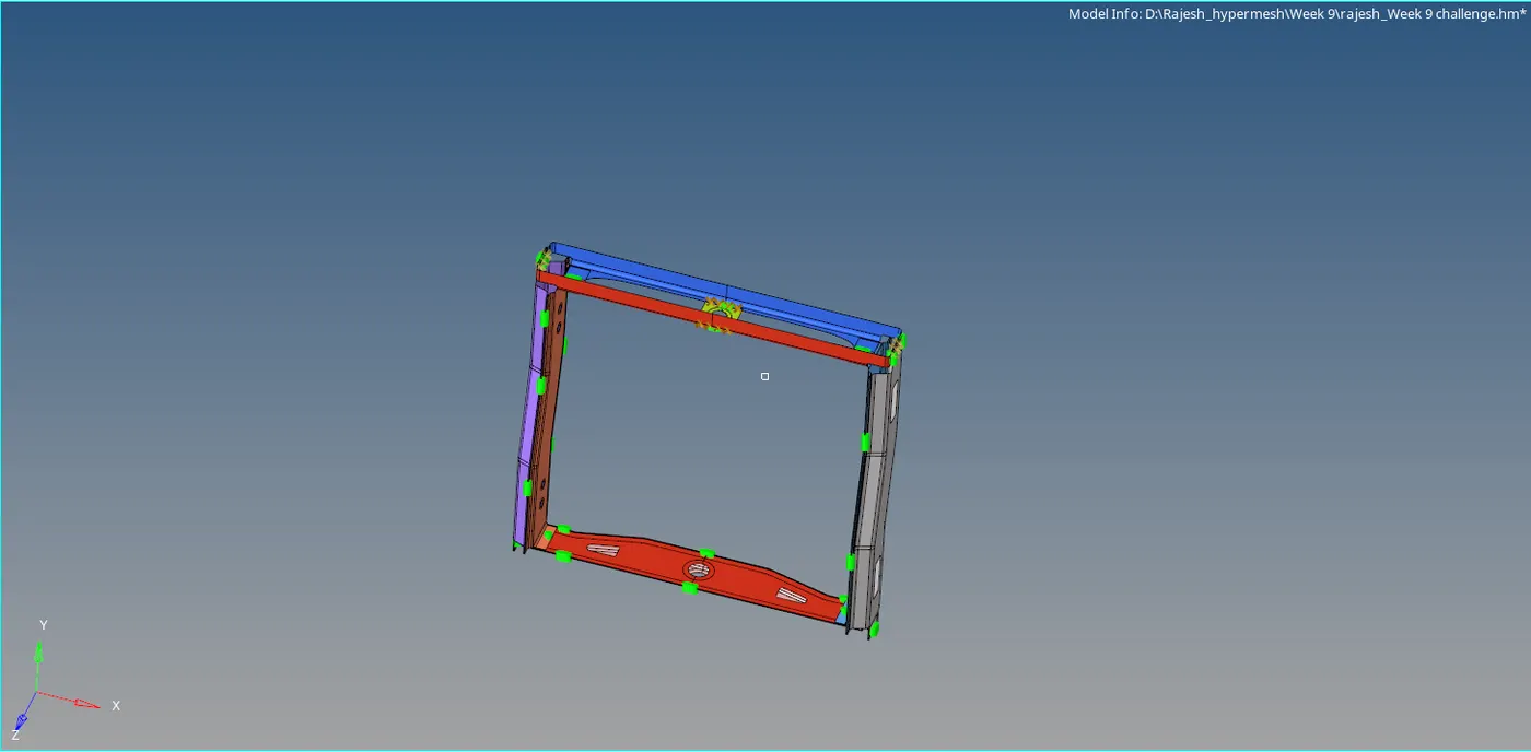
Step 2: Mesh the given component using automesh with 2D module with target element length as 5mm
2D>Automesh>create

Step 3: Remove the tria from free edges by dragging or using swap edge from the 2D quality index.
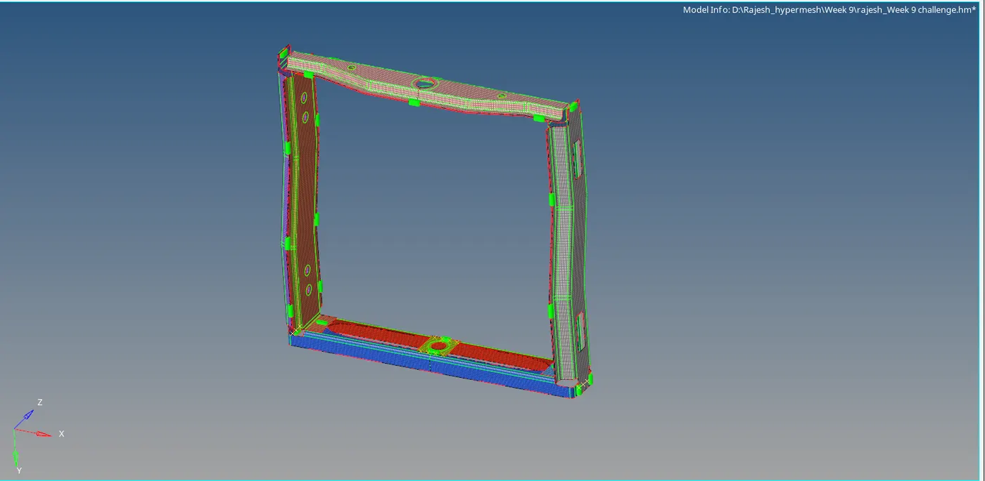
Step 4: Adding connections as per the given in the question.
1. Right_Rail_2 & Front_truss_1 with Seam-Quad(angled+capped+L)
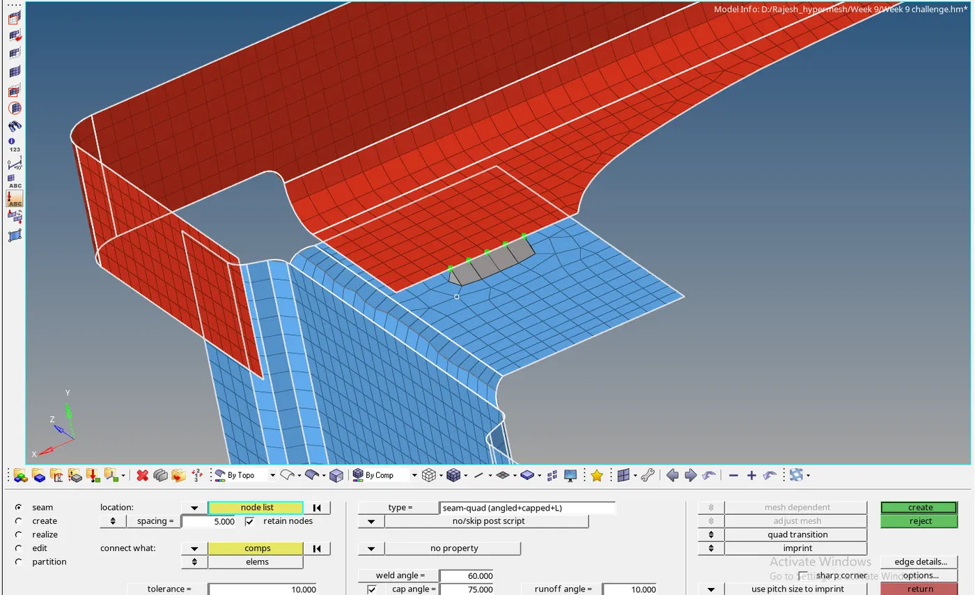
2. Left_Rail_2 & Front_truss_1 with Quad elements
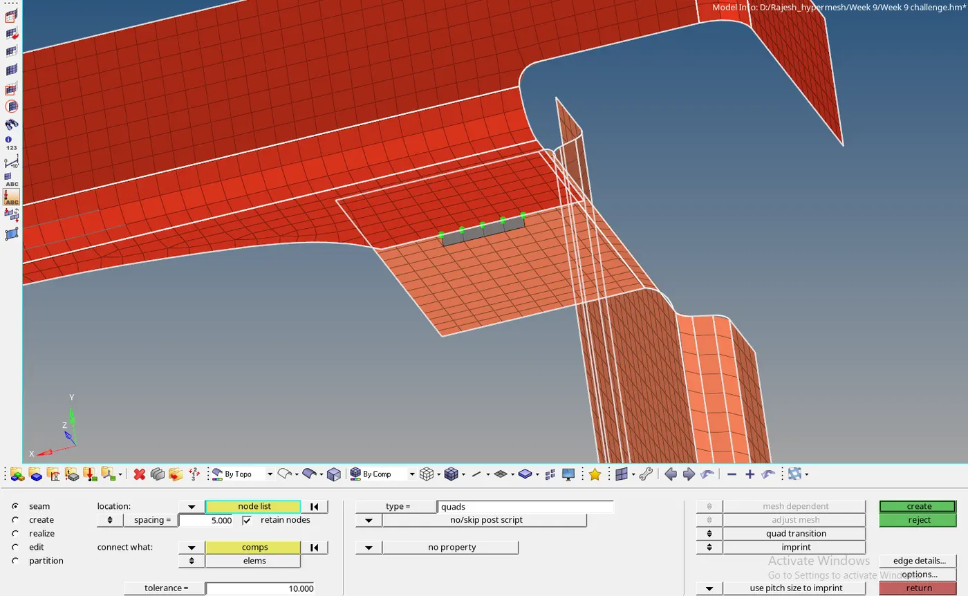
3. Front_truss_2, Front_truss_1 & Right_Rail_1 with Spot weld with 3 Layers and 5 mm Diameter
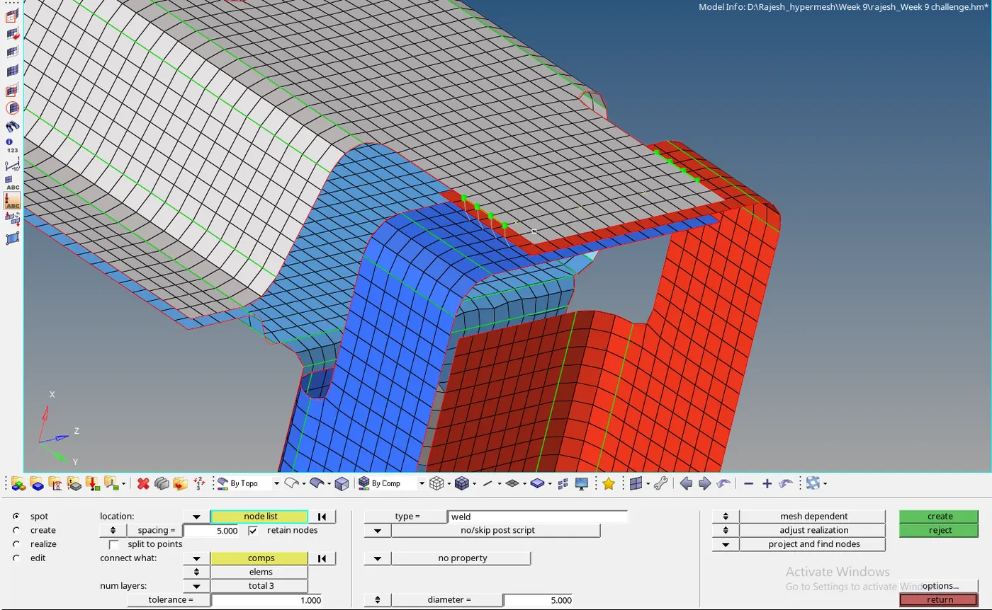
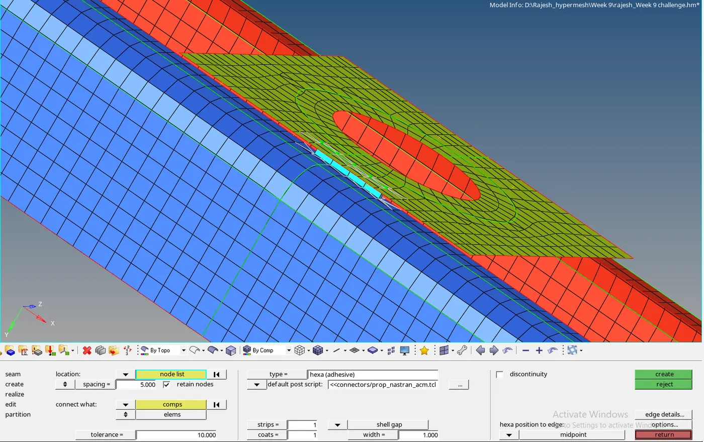
4. Front_truss_2, Front_truss_1 & Left_Rail_1 with Hexa (Adhesive)
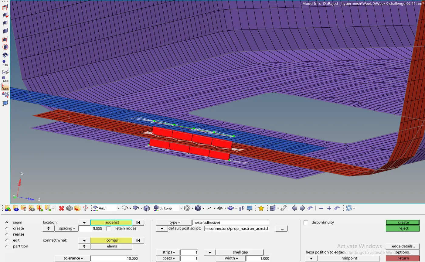
5. Rear_truss_2 & Right_Rail_2 with Bolt Connector
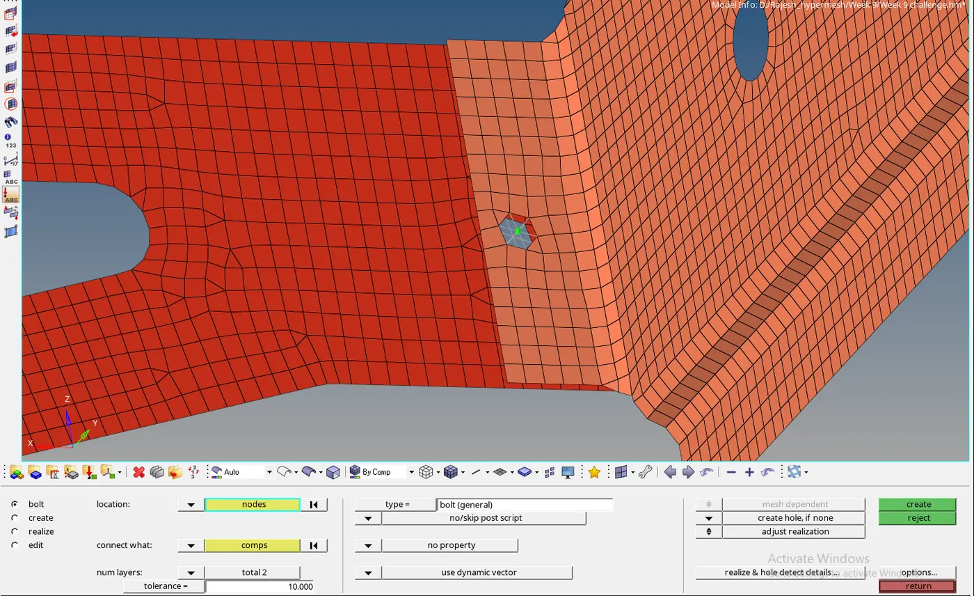
6. Rear_truss_2 & Left_Rail_2 with Bolt Connector
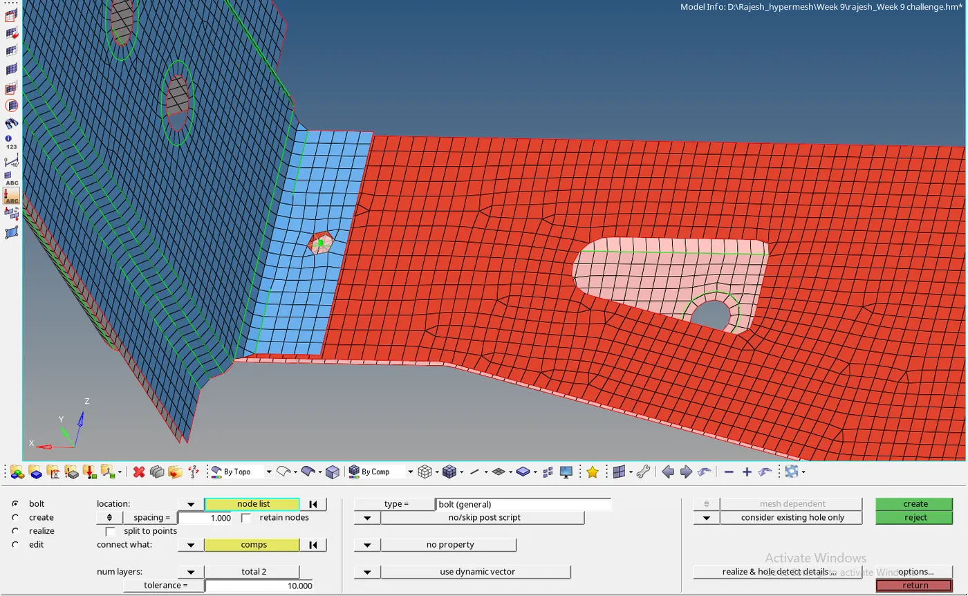
7. Right_Rail_1 & Right_Rail_2 with Spot-weld with Rigid Elements
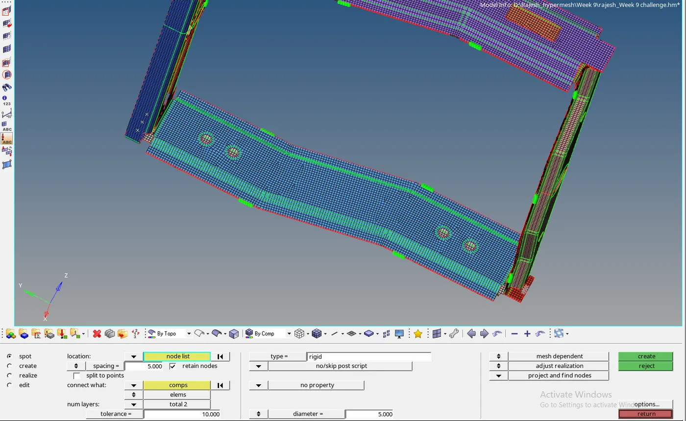
8. Left_Rail_1 & Left_Rail_2 with Spot-weld with Spring Elements
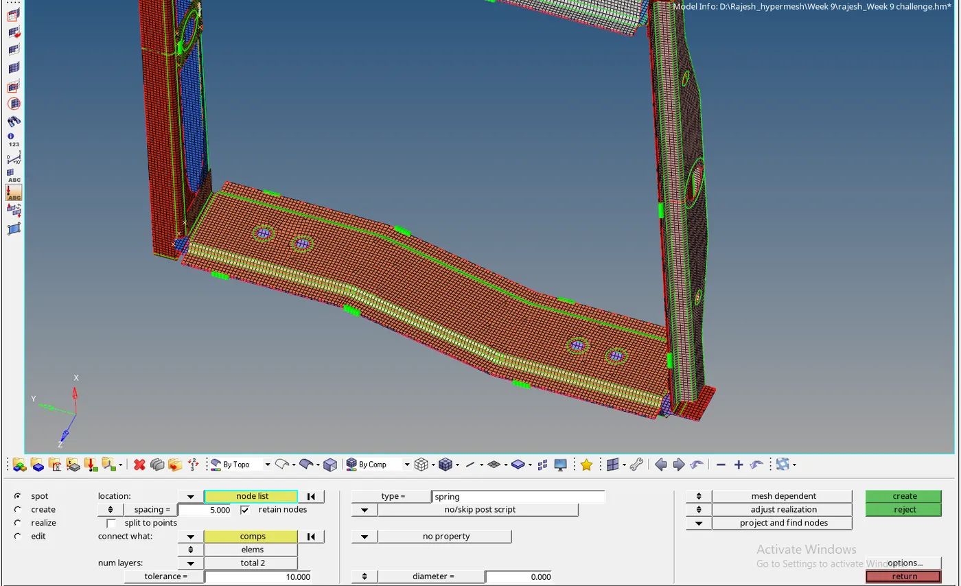
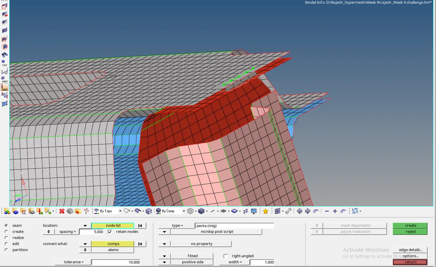
9. Rest all the component left Join them with suitable connectors. I use peng weld rear truss 2 and right rail 1 with penta mig and other I used seam quad and spot weld to connect.