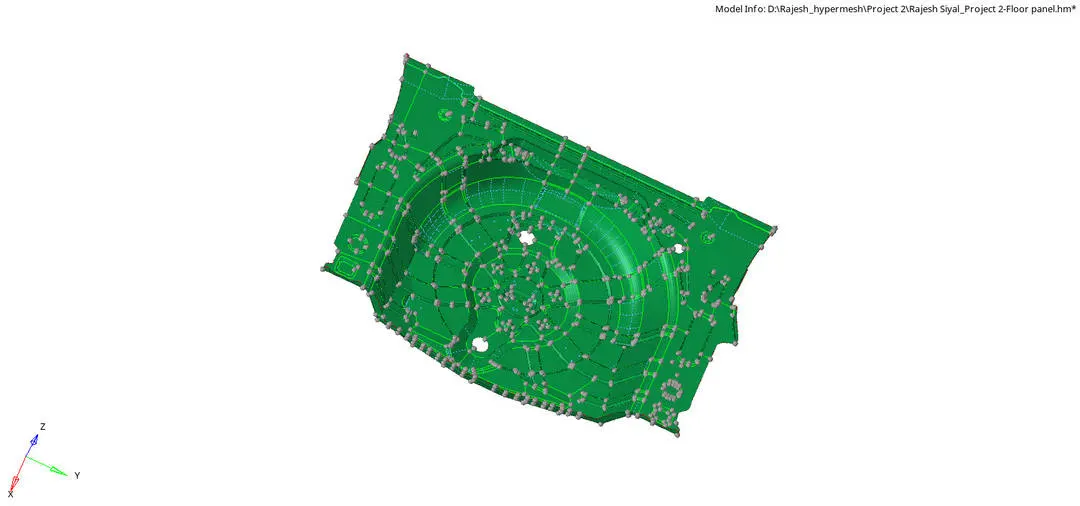
2D Element meshing of Floor panel in the automobile using Hypermesh
Mid Surface Extraction and 2D shell meshing using Hypermesh
AIM: Meshing of the given Plastic component by manual mid surface extraction and 2D shell meshing under the given quality criteria and assigning the thickness to the given component using Hypermesh.
OBJECTIVE:
- Geometry clean up of the given component.
- Mid surface extraction.
- Geometry cleanup of the mid surface.
- 2D shell Meshing with the given quality criteria.
- Assign Thickness and property.
BRIEF: The given model is a floor panel. The floor panel is where a Stepney wheel is attached.
PROCEDURE:
Step 1: Import geometry.
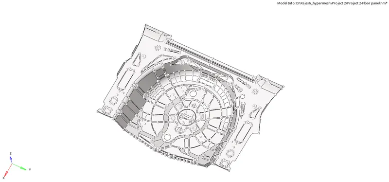
Step 2: Auto colouring to the component at organising into the main component.
Tool>color>comps>autocolor


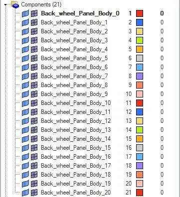
Step 3: Organise the different components into the main component made into a single component for further process.
Tool>organise>comps>desi component>move


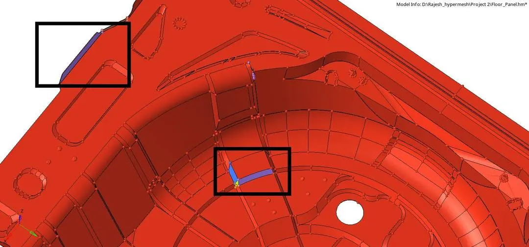
Step 4: Missing surface. Create the missing surface in the area using the ruled surface option under the surface tool.
Geom>surface>ruled surface>linelist>create


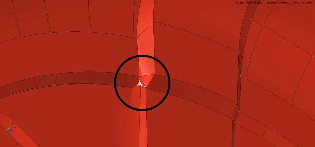
Step 5: Geometry cleanup and removing unnecessary features.
Tool>delete>surfaces>delete entity

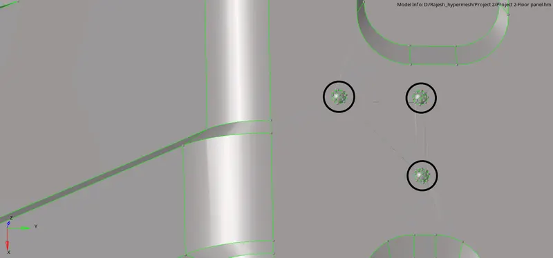
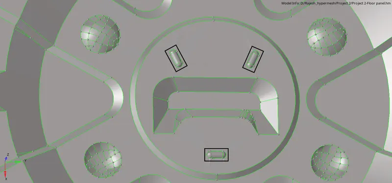
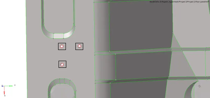
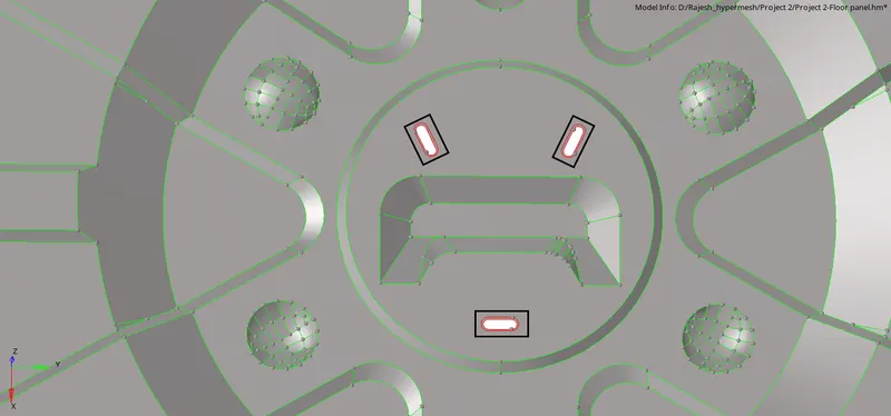
After deleting the unnecessary surface, re-create the surface using the filler option under quick edit tool
Geom>quick edit> filler or F11(shortcut)


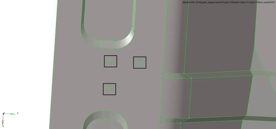
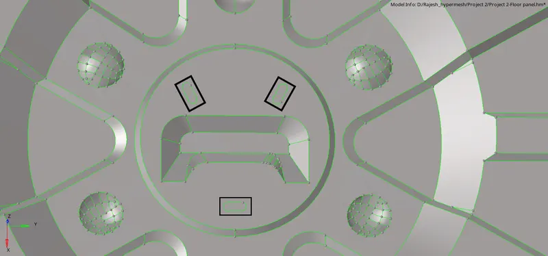
Step 6: Creating the mid surface of the given model by auto mid surface using offset + planes options.
Geom>mid surface>surface>extract
- Go to extraction option
- Change to offset + planes
- Then click auto extraction and click on the surface
- Click the surface as displayed and extract the mid surface.




Step 7: After creating a mid surface, there will be some distortion in the surface.
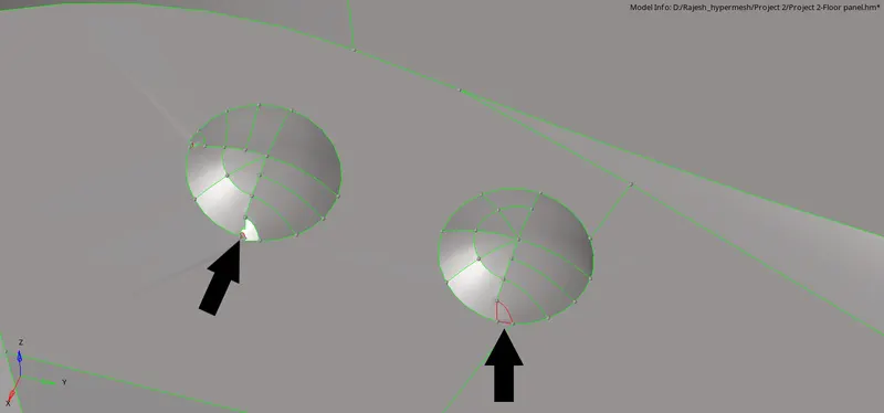
Delete the surface and use the position option tool.
Tool>Position>surfs> from N1, N2, N3> to N1, N2, N3> position
- Select the surface
- Select the ‘from N1, N2 and N3’
- And select the ‘to N1, N2 and N3’ and position


Tips: Select N1, N2 and N3 as per the position of the surface to be positioned and changing the placement of N1, N2 and N3 can also change the direction of the surfaces to be placed.
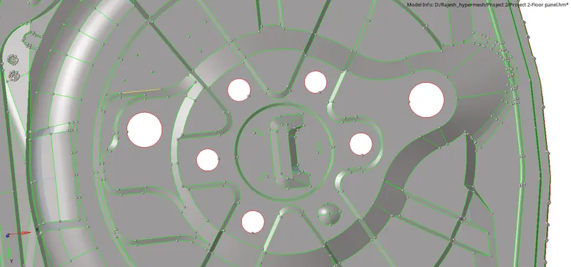
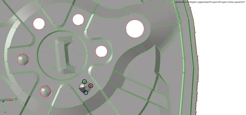
Step 8: Geometry clean up of the mid surface. Divide the surface by creating lines and toggling the unwanted lines.
Geom>Quick edit(F11)

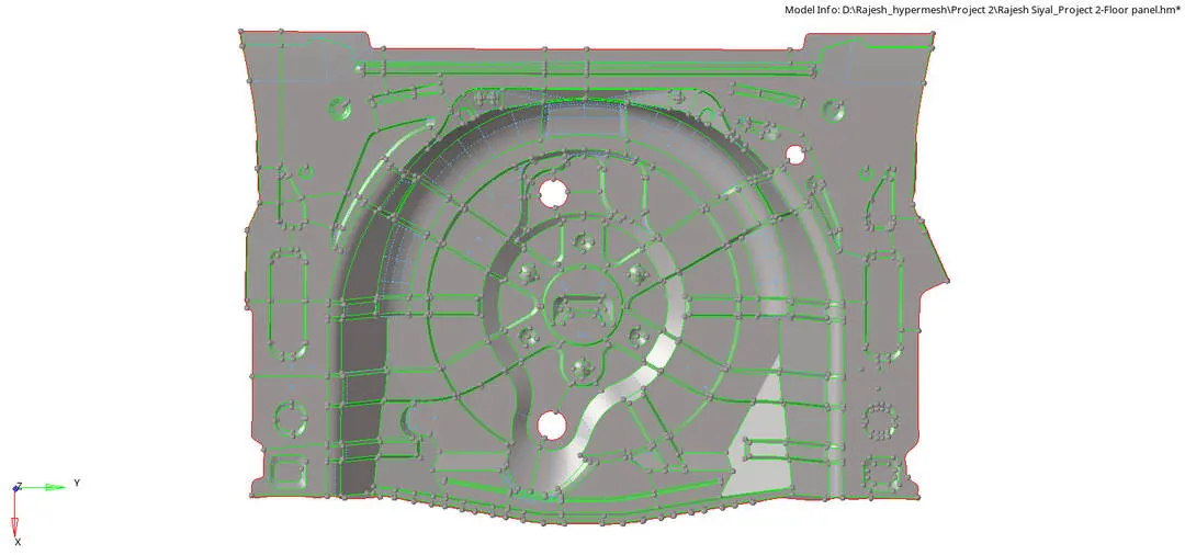
Step 9: (A) Create a 2D shell mesh on each surface with target Element Length as 5 mm and solve for the quality criteria.
2D>Automesh> Mesh or F12(shortcut)


Quality criteria:
|
S.N |
Quality Criteria |
Value |
|
1 |
Aspect Ratio |
5 |
|
2 |
Skewness |
45 |
|
3 |
Warping |
15 |
|
4 |
Taper |
0.5 |
|
5 |
Min. Length |
2mm |
|
6 |
Max. Length |
8mm |
|
7 |
Min angle Quad |
45 |
|
8 |
Max angle Quad |
135 |
|
9 |
Min angle Tria |
20 |
|
10 |
Max angle Tria |
120 |
|
10 |
Tria % |
10 |
(B) Check for the quality criteria and use the different options such as split, drag a trai, element optimize as per the given requirement.


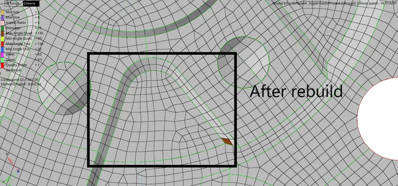
(C) To remesh the given surface, we can also use the tool under 2D as Rebuild, which will recalculate the element size and rebuild the mesh flow.
2D>rebuild mesh>rebuild
- Enter the element size.
- Import the criteria file setting.
- Do a box selection on the element which has to be rebuild.
- Rebuild.


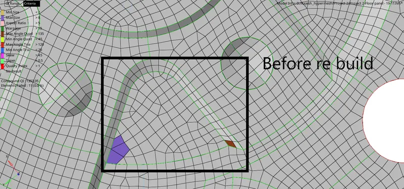
(D) Check for the free edge between the elements and check for the connectivity between the nodes
Tool> edge>elements>find


(E) To fix the connectivity issue, we need to give the tolerance value (should be less than minimum element size) and can perform equivalence to have connectivity between the nodes.
Tool> edge>elements>tolerance>equivalance

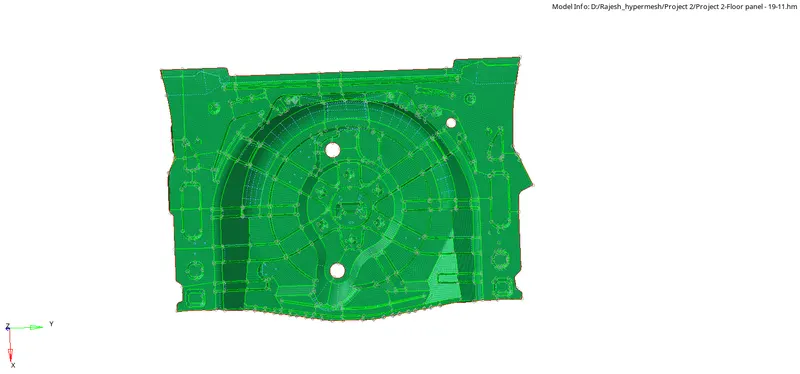
Step 10: After the meshing is done according to the given quality criteria, we need to smooth the mesh flow before post-processing.
2D>Smooth>elems>smooth or Shift + F12 (shortcut)
- Do a box selection on the elements where the smoothing has to be done for proper mesh flow.
- Give the number of iterations
- Anchor nodes are used to anchor the nodes on the geometry line or on the surface edge.


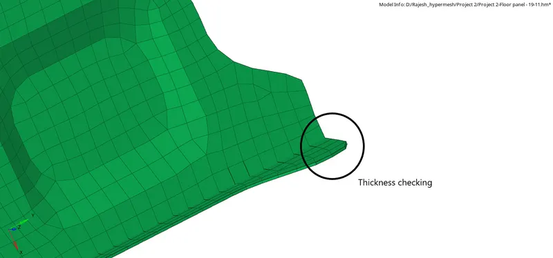
Step 11: Assign the thickness and material to the given component for the post-processing.
To check the thickness we need to change the visual setting to the 3D element size.

CONCLUSION: Learn to create 2D shell mesh and extract the mid surface of the plastic component using OptiStruct profile-Hypermesh.