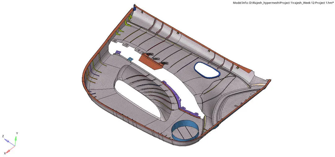
Mid Surface extraction & 2D element meshing of plastic component in Hypermesh
Mid Surface Extraction and 2D shell meshing using Hypermesh.
AIM: Meshing of the given Plastic component by manual mid surface extraction and 2D shell meshing under the given quality criteria and assigning the thickness to the given component using Hypermesh.
OBJECTIVE:
- Geometry clean up of the given component.
- Manual Mid surface (plastic component has varying thickness).
- Geometry cleanup of the mid surface.
- 2D shell Meshing with the given quality criteria.
- Assign Thickness and property.
BRIEF: The given model is a side door inner panel which the plastic component. The plastic component has a varying thickness, so the manual mid surfacing is performed to create 2D shell elements meshing for pre-processing.
PROCEDURE:
Step 1: Import geometry.
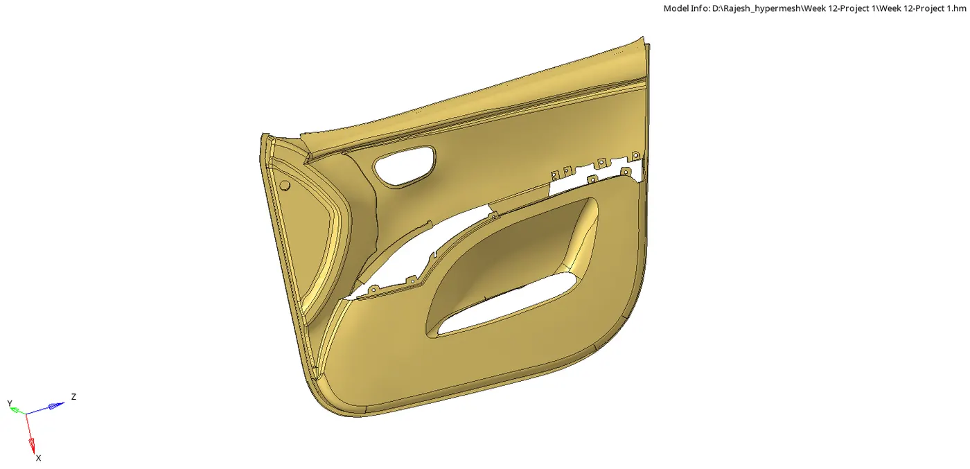
Step 2: Inspecting the model for any deformation or missing surfaces.
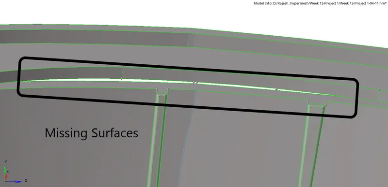
For this of missing surfaces, create a surface between the two free edges.
Geom>surface>linelist>create
Using the ruled surface option to fill the gap in the given component.


After performing the operation.
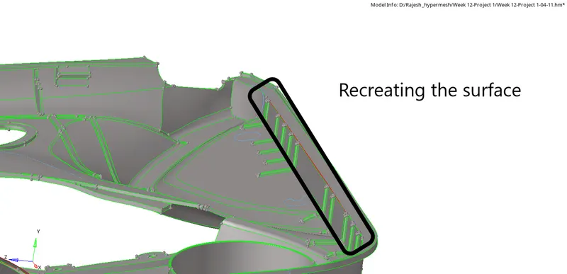
Step 3: Geometry cleanup and removing unnecessary features.
Tool>Delete>surf>delete (F2-shortcut)
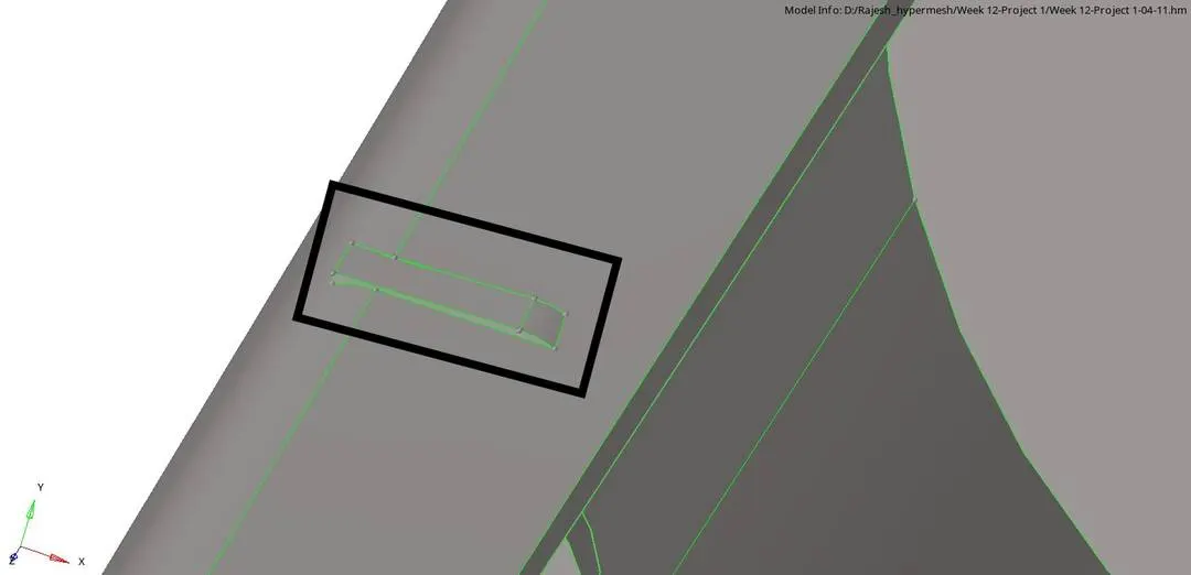
Step 4: (A) Defeaturing the fillet on the parent component before extraction of the mid surface, so that it won't fail for minimal element length.
Geom>defeature>surf fillet>surfs>find>remove
- Insert the minimum and maximum for fillet radius to find the fillets under the range.
- Select find and then remove the selected fillets.


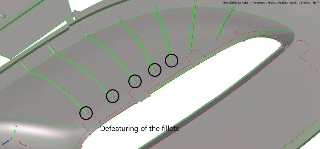
Sometimes some fillets don't get selected, so we can select manually using fillet to remove options to select the particular fillet.

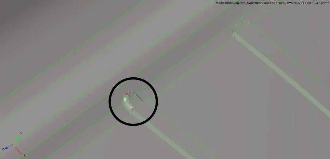
(B) After defeaturing all the fillets, we need to extend the opened surface and delete the unnecessary surfaces. To solve these issues we use the surface tool.
Geom>surface>drag along vector>lines>drag
- Select the lines of the surface which has to extend and enter the value to drag along the vector. (drag+ is for positive, i.e for the forward extension and drag- is for negative,i.e. for backwards extension).
- Select the N1 and N2. (N1 and N2 define the direction of the vector)
- Enter the units for the surface extension.


(C) After the extension of the surface, close the opening of the fillet using the ruled surface option to fill the surface.
Geom>surfaces>Ruled surf>line list>create

- Select the line and create the surface on each fillet end.
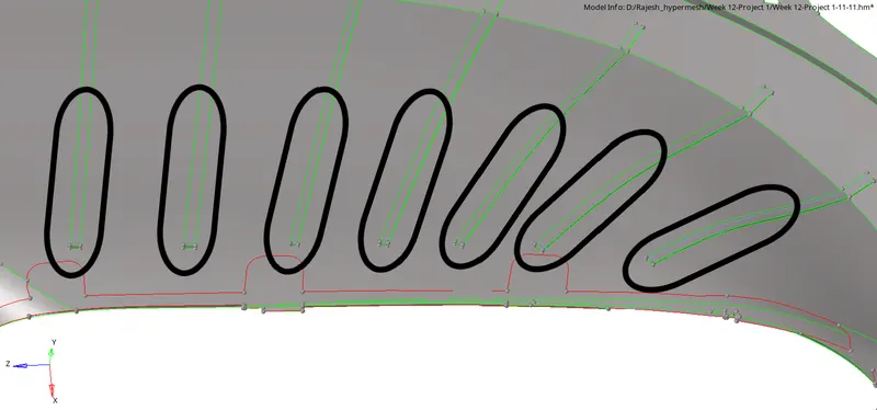
Step 5: Creating the mid surface of the given model by offsetting the surface according to the varying thickness. As it is a plastic component, the auto mid surface option cannot be used because of the varying thickness.
To extract the mid surface used offset option and the check for the thickness and offset according to the same.
Geom>surface edit>surf>offset
(A) To offset of any particular surface:
- Change the option of disjoint offset to continuous offset.
- Tick the update eccentricity and autocomplete separators.
- Select the surface and right-click to duplicate into the current component.
- Check for the vector normal and the hit the offset to create the surface.
- Performing the same operation, create the mid surface of the component.


(B) To create rib's mid surface used the option of final edit tools under mid surface option panel.
Geom>midsurface>final edit tool>side 1 surf> side 2 surf>extract
Select the opposite of the rib to extract the mid surface.



Step 6: After the extraction of the mid surface according to the varying thickness of each part and the ribs. Now extent the ribs to the surface.
(A) To extend the rib to the surface, we need to use the surface edit tool.
geom>surface edit>extend>lines:to extend over> surfs:to target>extend.
- Go the surface edit tool panel under Geom.
- Select the extend.
- Change the max extension to extend over edges(by clicking on the option) and cross extension to surfs: to target.
- Select the lines which have to extend and select the target surface on which has to be extended.

For extending the ribs to the surface we need to create a region below the rib so that the entire surface doesn't get compress and distortion happens on the surface.
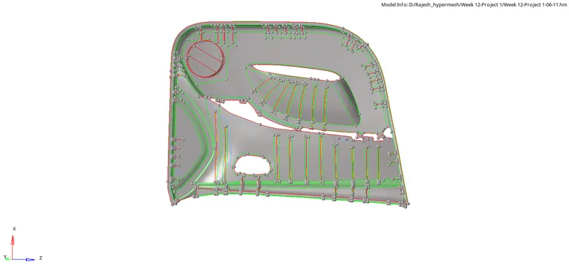
(B) For Proper feature capturing of the given part we need to re-create hole on the mid surface.
Select the circle on the parent model and create a temp node.
Geom>nodes>Arc center>lines>create
- Change to lines from nodes to get the node on the center of the circle.
- Now project this node to the mid surface.
- Create a circle using the projected node with the defined radius.



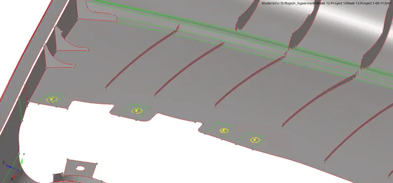
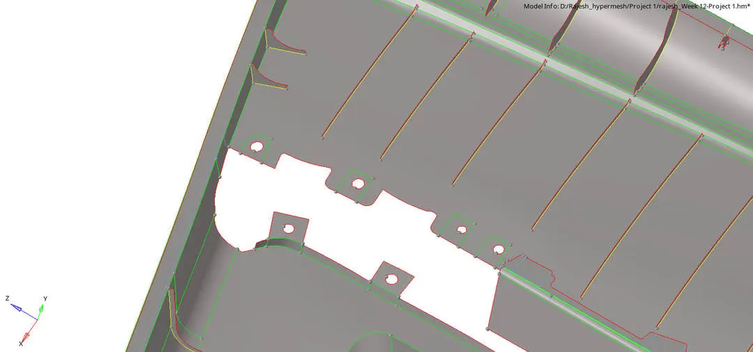
After the circle is created, now trim the surface using surface edit tool to capture the feature.
Geom>surface edit>trim with lines>surfs>free lines>trim
- In trim with lines, use the option lines and change along the vector to normal to the surface.

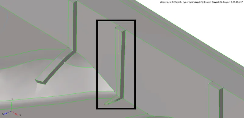
(C) For one of the ribs to extract the mid surface was not proper to, so we created a midline and then trim and crated the surface to capture the feature of the rib.
Geom>lines>linelist>create
- Select the line lists to create the midline of the particular on the surface of the rib.
- Then Trim with lines using surface edit tool by selecting the midline of the rib and the opposite surface.
- After the surface is trimmed, now create the mid surface for the rib by using the ruled surface tool.


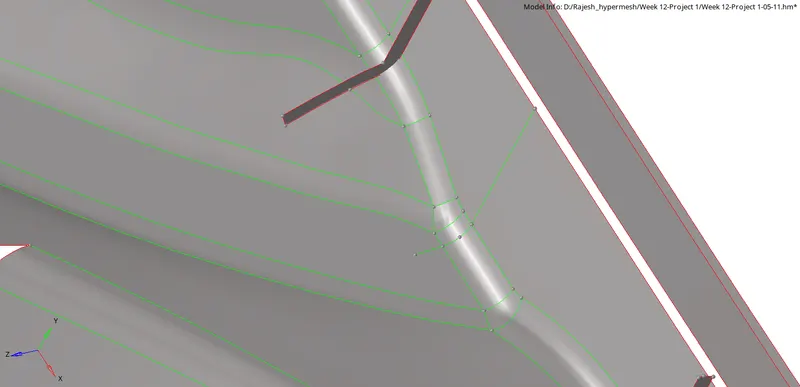
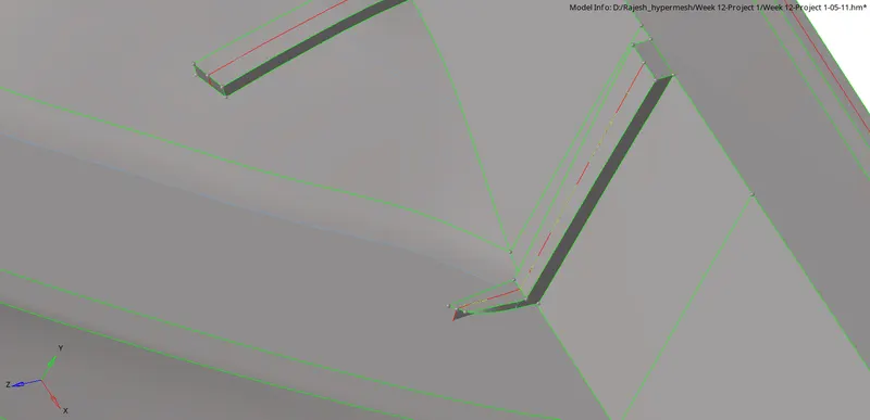
Step 7: Geometry clean up of the mid surface. Divide the surface by creating lines and toggling the unwanted lines.
Geom>Quick edit(F11)


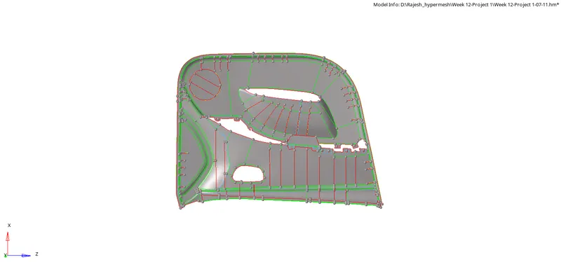
Step 8: Create a 2D shell mesh on each surface with target Element Length as 4mm and solve for the quality criteria.
Quality criteria:
| S.N | Quality Criteria | Value |
| 1 | Aspect Ratio | 5 |
| 2 | Skewness | 45 |
| 3 | Warping | 15 |
| 4 | Taper | 0.5 |
| 5 | Min. Length | 2mm |
| 6 | Max. Length | 6mm |
| 7 | Min angle Quad | 45 |
| 8 | Max angle Quad | 135 |
| 9 | Min angle Tria | 20 |
| 10 | Max angle Tria | 120 |
| 10 | Tria % | 10 |
To create proper node connectivity between the ribs and the surface perpendicular to it, we need to use the imprint option.
2D>Mesh edit>Imprint>create


In the imprint option, change the source to comps to node list and elems.
- Change both to destination.
- Giver the number of layers and assign a value (it will make the connectivity between the nodes and re-mesh the elements up to the number of elements layers which we give).
- Check for the auto-detect box
- Give the target element size and hit create.
- Select the elements adjacent to the ribs and the surrounding as per the number layers entered.
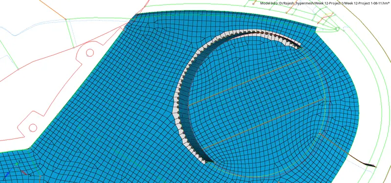
After meshing the entire model.
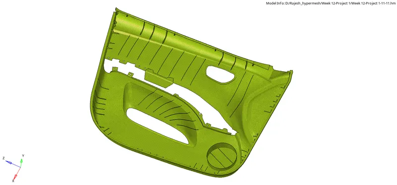
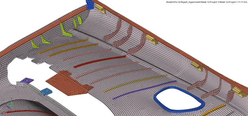
Step 9: Create the different component as per the thickness and organise the elements into the respective component.
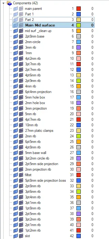
Step 10: Assign the thickness and material to the given component for the post-processing.
To check the thickness we need to change the visual setting to the 3D element size.

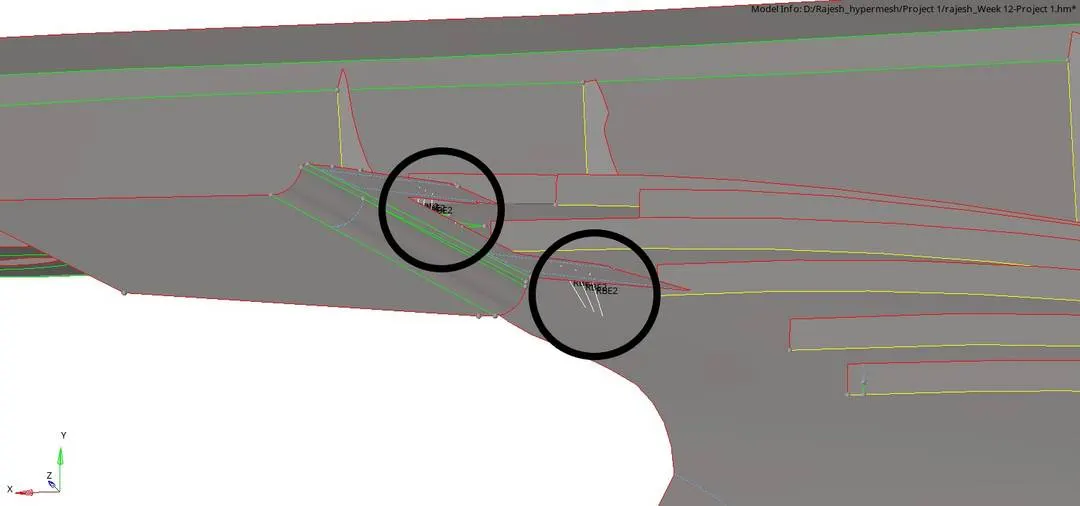
Step 11: Create rigid between the two components.
1D>rigids>create
- Select the node on the opposite component to create rigid elements.


CONCLUSION: Learn to create 2D shell mesh and extract the mid surface of the plastic component using OptiStruct profile-Hypermesh.