2D element Meshing of Automobile part "Hood" using Hypermesh
WEEK 6 CHALLENGE
Extraction the Mid-surface and Meshing the component using Hypermesh
AIM: To extract of mid surface and advance meshing of Automobile's front Hood panel with manual geometry clean up.
BRIEF: Hood is also known as ENCON, serves as an access panel to the engine compartment of an automobile. It consists of the outer and inner panel to meet various design requirements and safety of the passenger. There are following safety requirements taken into consideration of the design of the hood.
- Pedestrian safety.
- Vehicle quality.
- Occupant safety.
- Styling.
- Manufacturability.
Hood is also known as Bonnet. It is the front portion of an automobile. It is used to decorate the car and it is designed aerodynamically to reduce the air effect. The bonnet is generally used to give access to the engine, radiator and many other parts. Hemming is the important term in the design methodology of the hood design.
Hemming: It is a metalworking process in which a sheet metal edge is rolled over into itself. This process ensures both inner and outer panels are interlocked together. Corner relief must be provided to avoid local stress generation and tearing sheet metal.
There are 5 components in this model to be mesh. Hypermesh is used to create 2D shell mesh for pre-processing. It used to create the mid surface of the component which has a thickness less than 6mm and shell mesh is done on the mid surface. The following are the components which have to be mesh.
- inner_extract_body1
- outer_extract_body1
- hinge_reinforcement_extract_body1
- hinge_reinforcement_extract_body2
- latch_reinforcement_extract_body1
PROCEDURE:
The procedure is the same for all the component. The critical criteria for this design are as follows:
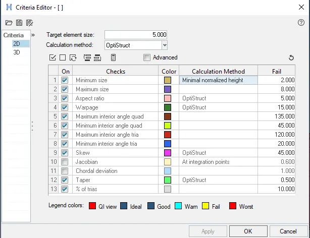
Step 1: Import the step file.
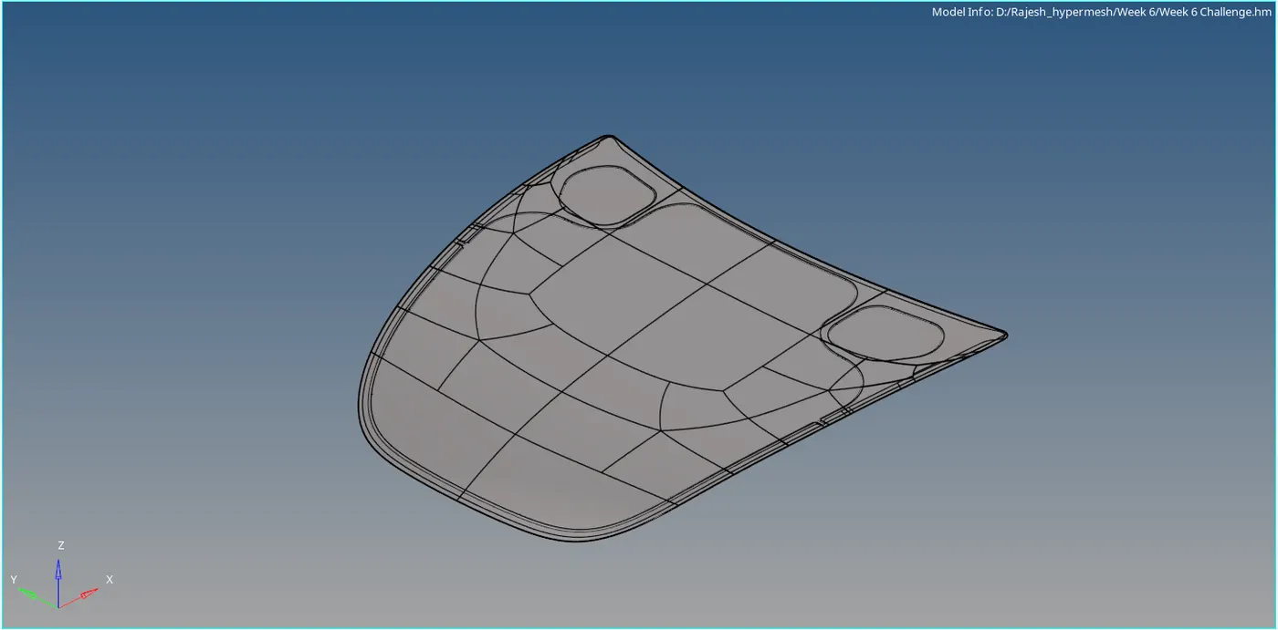
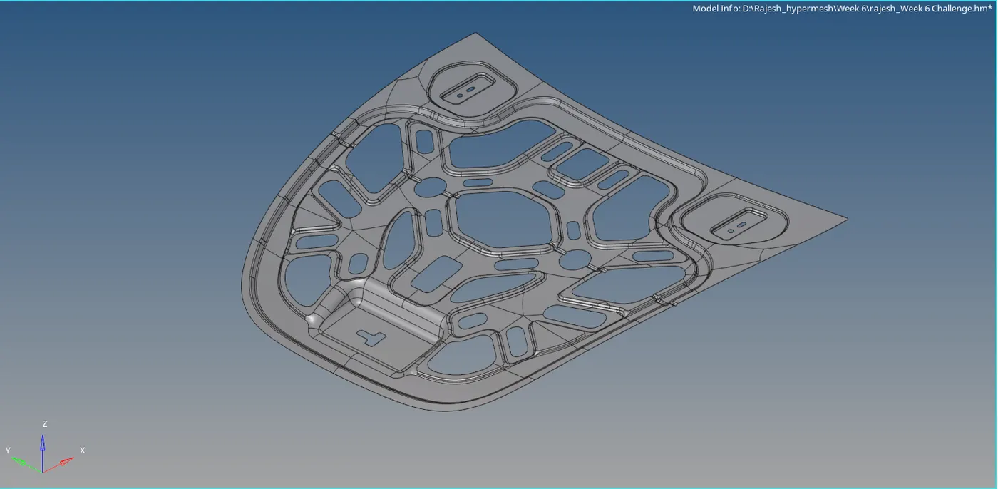
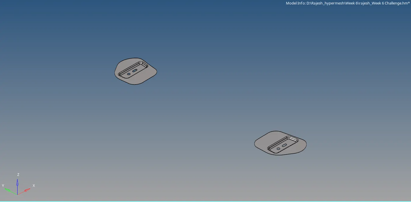
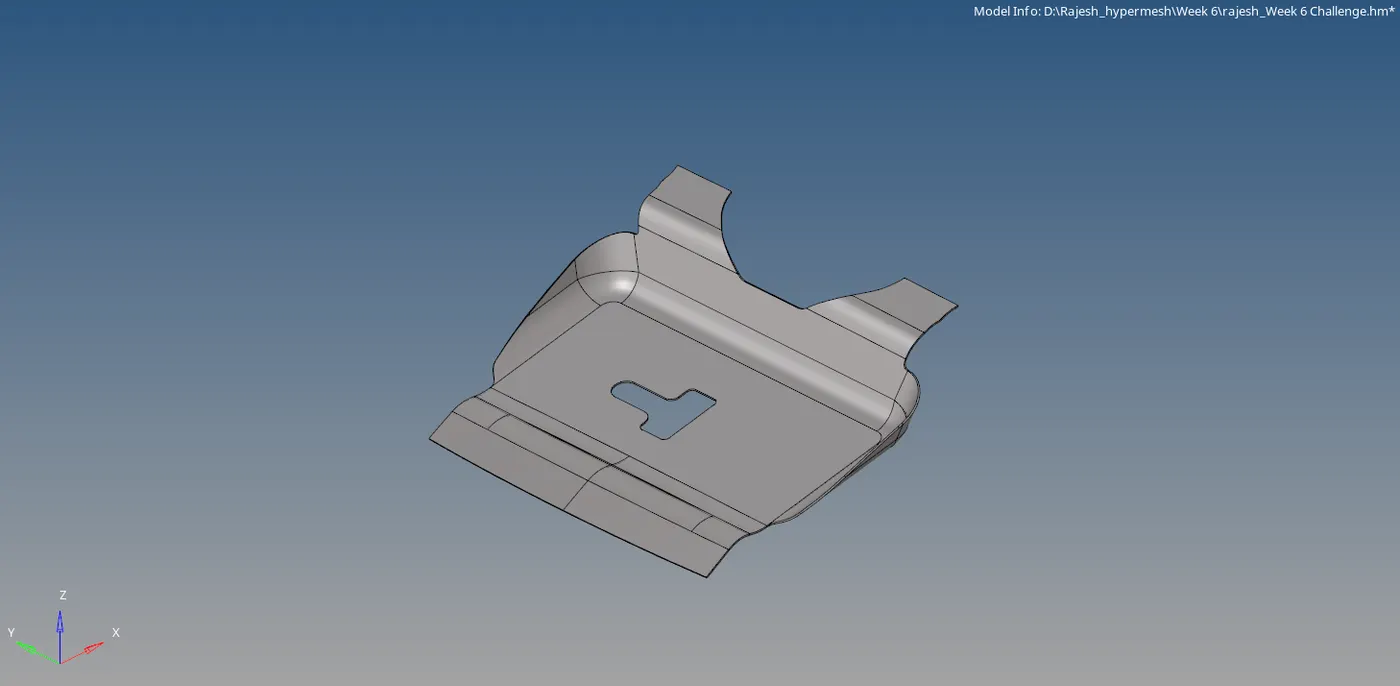
Step 2: Inspect the model for any missing or duplicate surface and also check for free edges and deformation. (For easy finding, change to topology mode & make it wireframe).
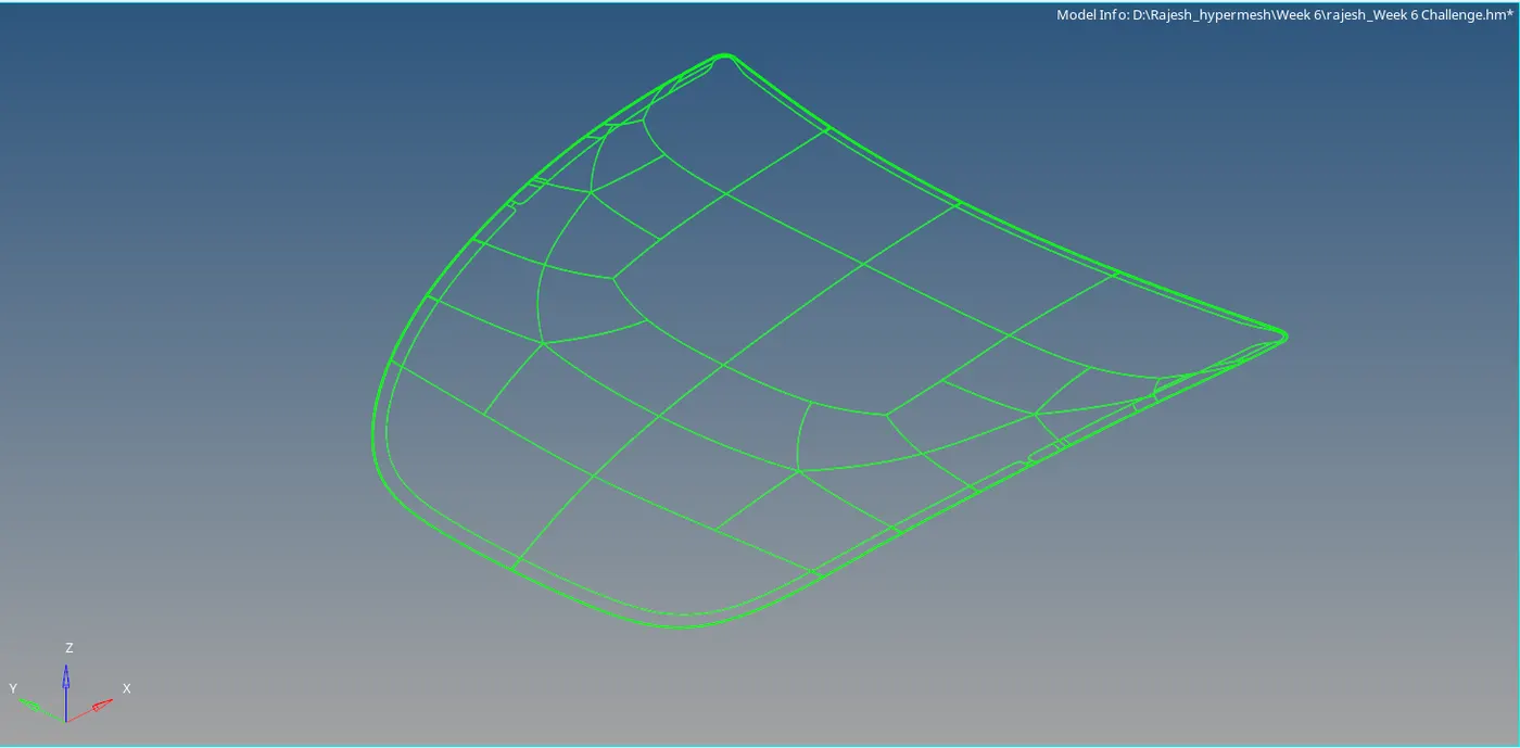
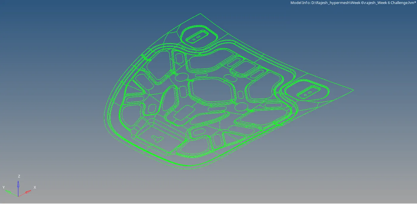
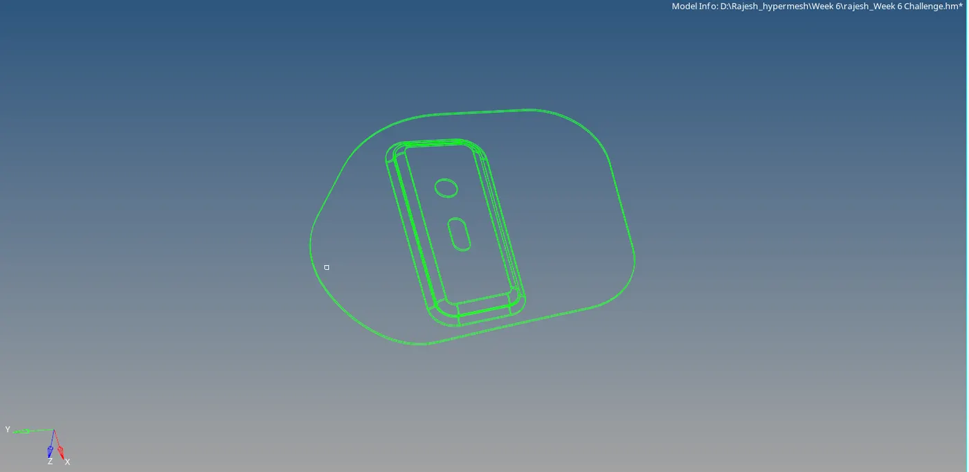
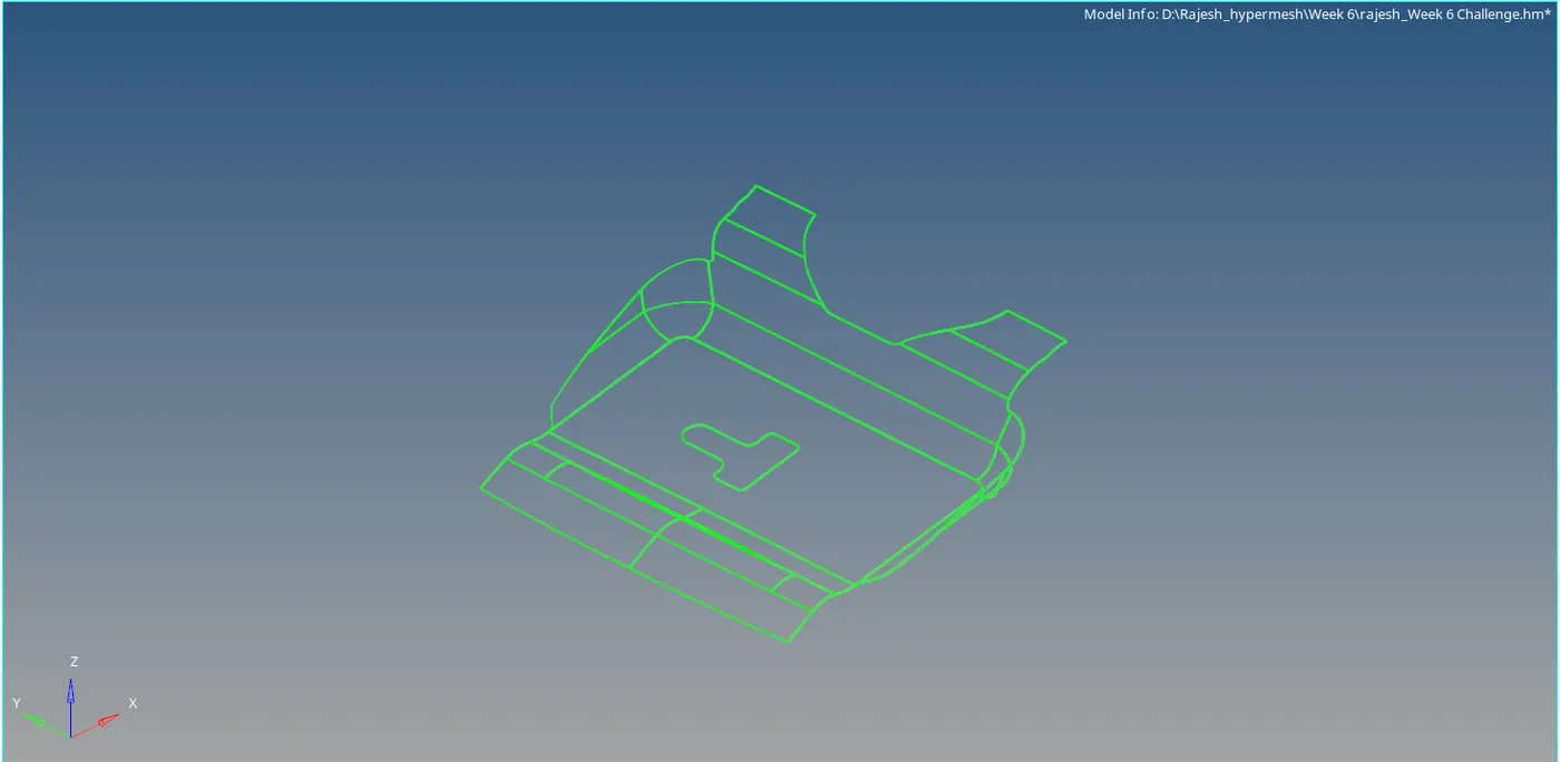
Step 3: Extract the mid surface for each component. We select skin offset for this component as it which result in better accuracy.
Geom>Midsurface>Extract
Mid surface type:
(I) offset+ planes + sweep: The places where a piece of the plane or a piece of a sweep surface can be used as a middle surface.
(II) offset + planes: the places in the model where a piece of the plane can be used as a middle surface.
(III) offset: Create pieces of the middle surface by offsetting the model's side surfaces towards the middle. This is the traditional way of extracting mid surface in hypermesh.
(IV) skin offset: This method automatically detects the two largest faces on the model, detects the thickness, and then creates the middle surface by offsetting one of the faces towards the other one by half of the thickness. This is the quickest method for creating a mid surface.

Step 4: Geometry clean. Use the quick edit tool to do the manual geometry cleanup of the component. Toggle the lines for better meshing and good feature collection.
Geom>Quick edit(F11-shortcut)>toggle edge
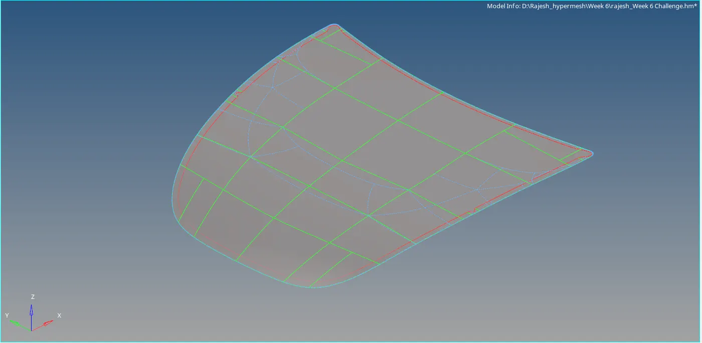
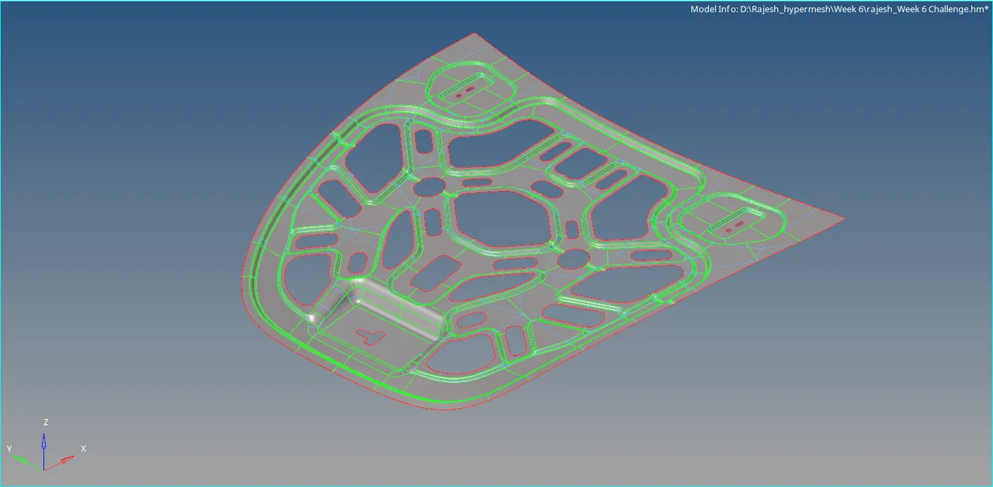
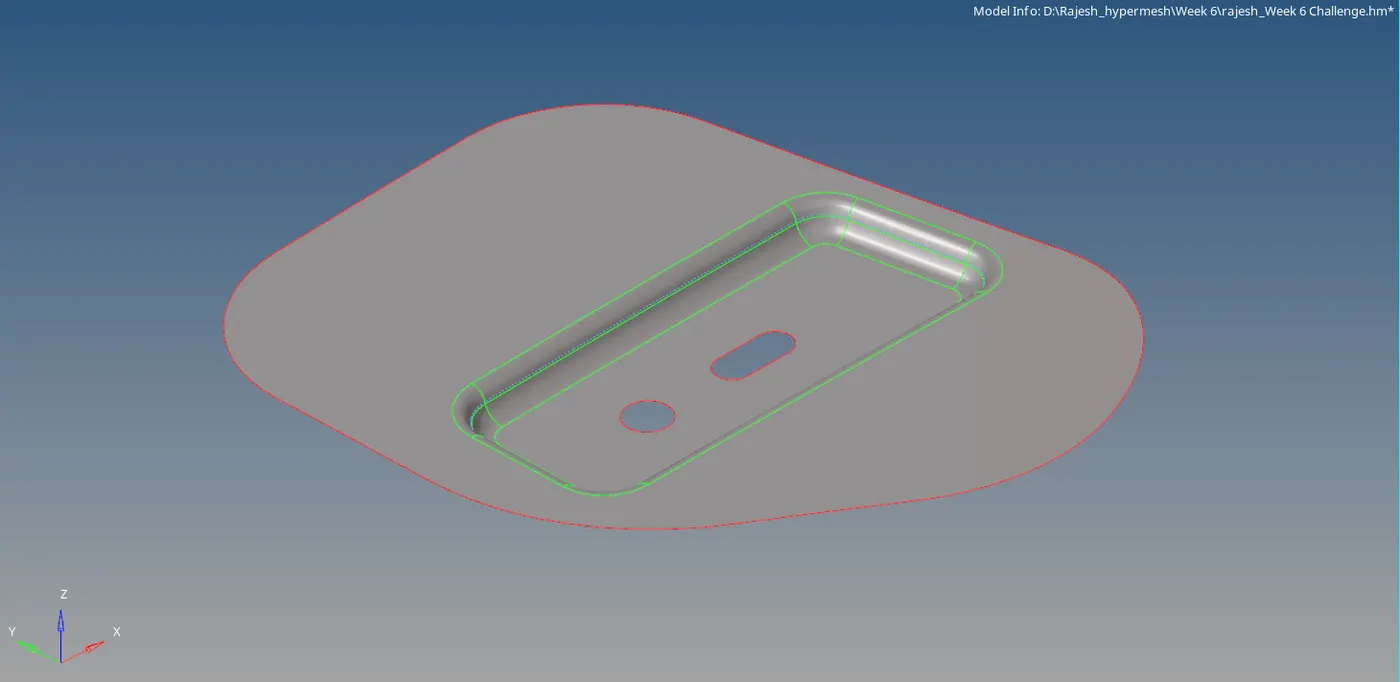
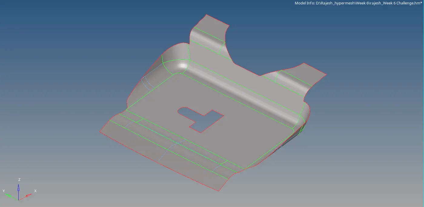
Step 5: Meshing. Use automesh to mesh the respective surface according to a component which is being meshed. I used the mix element type with the target element size as 5mm.
Note: Always keep the component in "make current" before meshing.
2D>automesh>create.

Things to check:
- Create mid lines or divide the surface into multiple small areas for good mesh flow.
- Re-mesh the areas for better mesh flow and use the below rules for trai management.
For re-meshing, change to elem mode and select the particular sets of the element to re-mesh. (Tip: always select box type selection for better control on element management and select the region associate with the free edge). - Check for symmetry in the component, so that we can create an element on one side and reflect the same as we can save a massive amount of time in the process.
- Tools>reflect>select the element> N1,N2,N3,B>reflect.
N1, N2, N3 defines the plane and B defines the base point from where the component is symmetry.
Trai management:
- No trais in corners or edge
- No opposite trai
- No back to back tria
- No trai in fillet or hemmings
- No rotational quats
- No trais should share a boundary line with the feature line
- Connectivity between elements
- Split and perform mesh
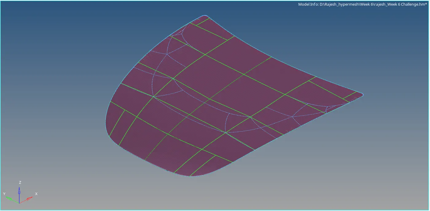
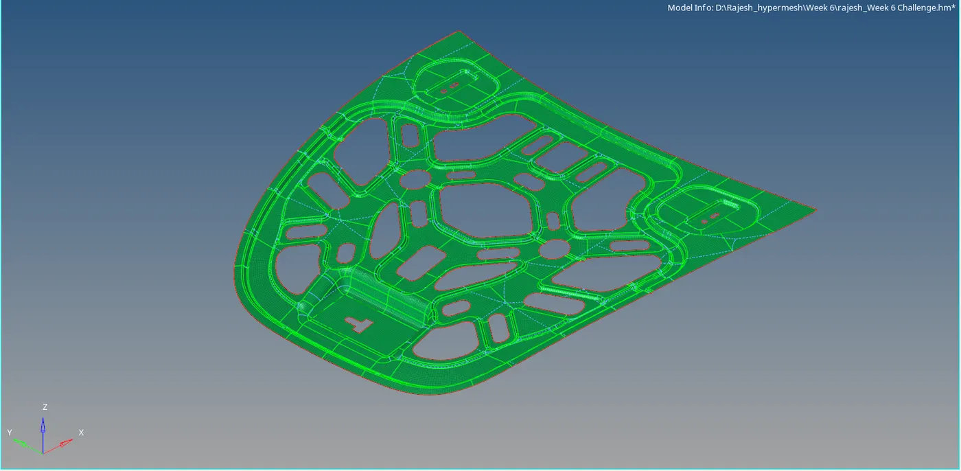
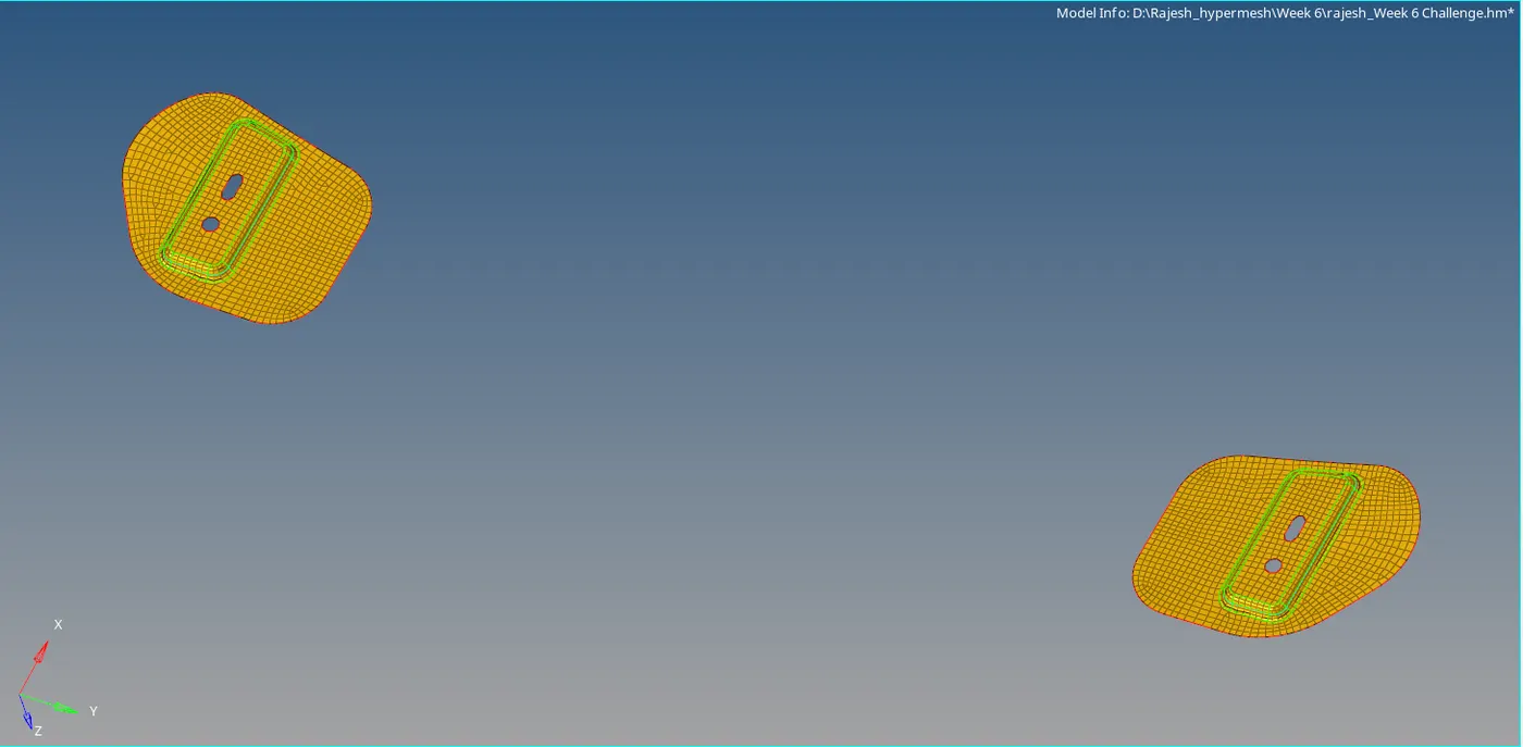
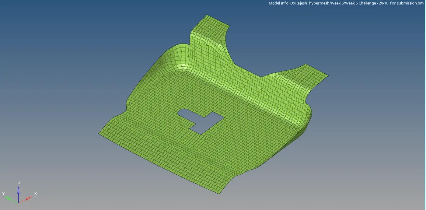
Step 6:Check for quality criteria and minimize the errors using the above criteria.
Step 7: Use the smooth option to smoothing the mesh flow over the region.
Shortcut: Shift+F12
CONCLUSION: Learn about the automesh, manual geometry cleanup and tria management rules for better mesh flow and how to select the mid-surface option based on the type of component by checking the thickness over the component.