CONNECTIONS FOR FRAME ASSEMBLY
AIM: To mesh the frame assembly and assemble the components with suitable connectors
PROCEDURE:
- Import file to hyper work
- Delete solid surfaces
- Geometry clean-up
- Defeaturing
- Meshing
- Connections
IMPORT GEOMETRY FILE TO HYPERMESH
Since we are importing a CAD geometry, the format will be either of the 2 industrial standards:
STEP (Standard for the Exchange of Product data).
IGES (Initial Graphics exchange specification).
But here we dont have any . STEP or . IGES file to import
we got here geometry model we can directly import it to hypermesh
For open
Go to File >> Import >> Select geometry >> Open the model >> Click the model >> Import
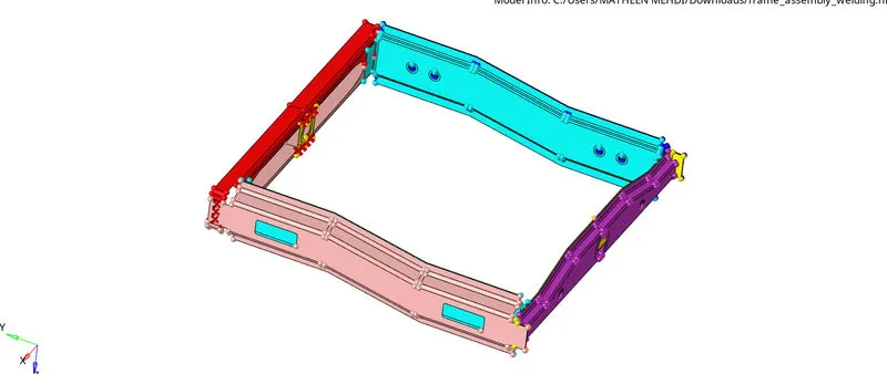
MODEL IMPORTED
DELETE SOLID SURFACES:
Now change the AUTO mode to TOPO mode to see the model imported is in solid are with out solid
Suppose imported model is in solid then we have to delete the solid component
Switch to Topo Mode, the solids will be highlighted in green colour .
Delete [F2] > Solids > Displayed > Delete Entity
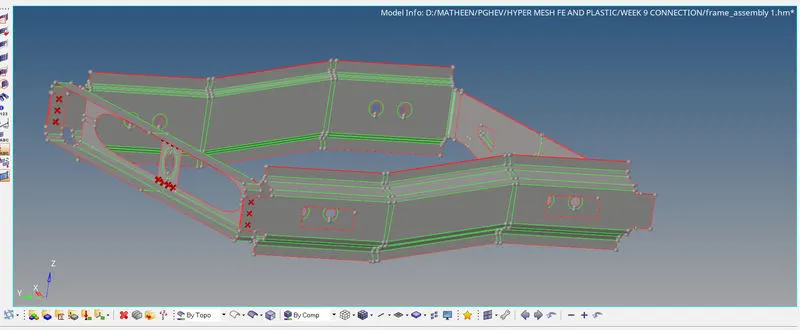
TOPO MODE
GEOMETRY CLEAN UP:
Once the model is imported move to geometry clean up just to check whether there any extra surface or free edges or missing surface will present or not
Here in the above models no errors are present
To check a errors
Go to visualize panel >> Disable shared edges and all except free edges
In this model we dont have any error
But here we have to create a washer split for the hole area to get proper mesh flow and proper connection
for that
Go to Quick edit >> washer solit >> enter offset value as 5mm >> create
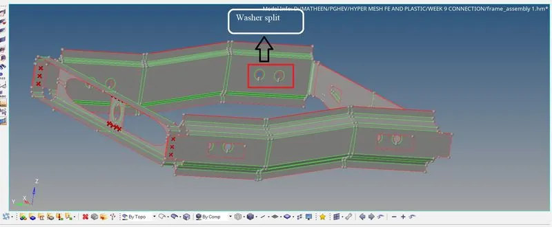
WASHER SPLIT
DEFEATURING:
In hyper mesh, after you mesh a product for any kind of analysis, the end product is a meshed product. Most of the times it so happens that, some small holes or some small fillets or some small radii are left out which are not functional and unnecessary. We need to remove these unwanted features in order to obtain a final correct analysis. The process of removing these unnecessary, non-functional features is called de-featuring.
defeature all unwanted lines which is less than the given minimum length
For defeature
Go to quick edit >> Toggle all unwanted lines
Here in this model we are not considering any quality criteria we are just focusing about connections
MESHING:
FEA stands for the finite element analysis which means that elements are analysed and integrated over a region to derive the final result. so, in a continuous member, which in reality are everything starting from a pin to automotive parts. there are infinite nodes and it’s not possible to solve an infinite equation. so meshing is carried out so that we can desecrating that continuous member into number of finite nodes. and hence go for solving the equations. after that interpolate the results for entire domain.
Rules of mesh :
For better mesh flow we need to fallow some rules :
- Opposite tria's are avoided.
- Flat surface trai's should be avoided by merging them using split.
- Avoid trai's near to hole region.
- Hole feature should be in even numbered.
- Avoid tria's at the perimeter line.
- Avoid zig-zag mesh flow.
- Avoid rotating quads.
- Divides the large surface into small parts using split for meshing.
- Defeature the area which are going to fail the quality criteria
Mesh the given components with a given target element size
Now mesh the component
Go to geometry page >> Select 2D >> Select auto mesh >> Select surface >> Create
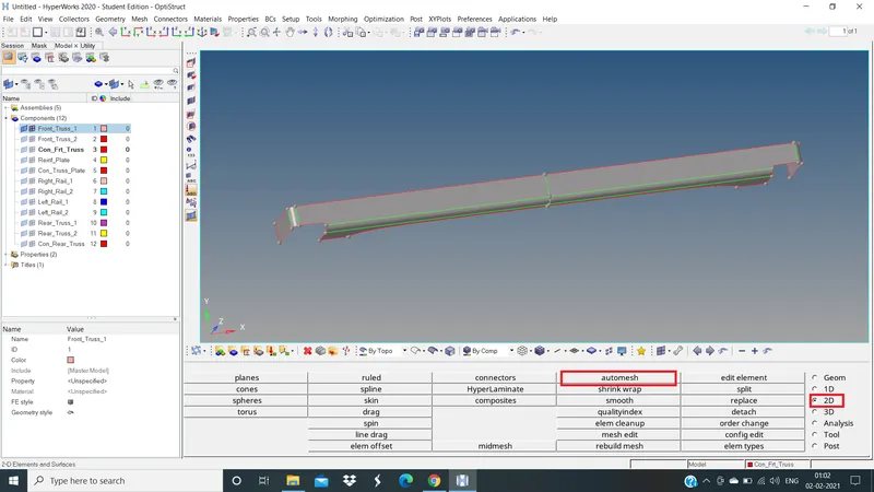
AUTOMESH COMMAND
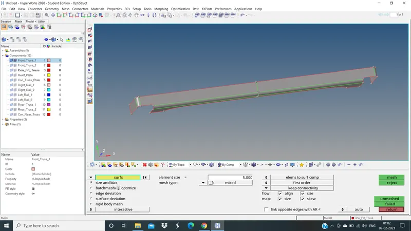
SELECTING SURFACE TO MESH
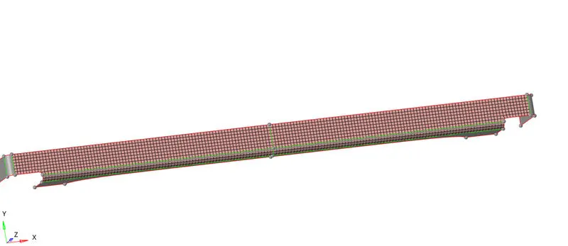
MESHED SURFACE BY SURFACE
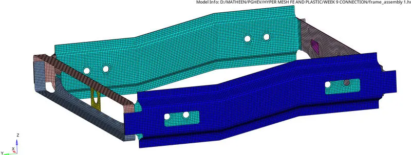
MESHED GIVEN COMPONENT
CONNECTIONS:
What are Connectors?
Connectors are geometric entities, which are primarily used to represent the CAD geometric connection in terms of FEA. Connections can be created as a spot-weld, seam-weld, adhesive, bolts and masses. A realized connector will be considered as the successful representation of a CAD model in preprocessing and the connecting parts can be considered as connected.
States of Connectors:
There are three different states in the connector's realization. They are
- Realized Connector
- Unrealized connectors
- Failed connectors
State 1: Realized connectors
Successful creation of connectors will be represented in Green colour as shown below:
State 2: Unrealized connectors
Unrealized connector will be represented in Yellow colour as shown below:
State 3: Failed connectors
Failed connectors connector will be represented in Red colour as shown below:
Now we are going to create some connectors and we look into the possible way to realize the connections
1. Right_Rail_2 & Front_truss_1:- Seam-Quad(angled+capped+L)
2. Left_Rail_2 & Front_truss_1:- Quad elements
3. Front_truss_2, Front_truss_1 & Right_Rail_1:- Spot weld with 3 Layers and 5 mm Diameter
4. Front_truss_2, Front_truss_1 & Left_Rail_1:- Hexa (Adhesive)
5. Rear_truss_2 & Right_Rail_2:- Bolt Connector
6. Rear_truss_2 & Left_Rail_2:- Bolt Connector
7. Right_Rail_1 & Right_Rail_2:- Spot-weld with Rigid Elements
8. Left_Rail_1 & Left_Rail_2:- Spot-weld with Spring Elements
9. Rest all the component left Join them with suitable connectors
1. Seam-Quad(angled+capped+L):
Seam Weld:
The process of joining the workpiece which are made of similar or dissimilar materials along a continuous seam is known as Seam weld. In hypermesh, seam panels under connectors will help to represent the Seam weld connection between the components.
- Steps to be followed to create Seam - Quad (angled+Capped+L) Weld:
- Select 2D → Connectors → Seam option.
- Now select the location, where the Weld has to be created, by clicking the “node list”.
- Tick the checkbox of “retain nodes” option, to retain the position of the nodes, while creating and realizing a connector.
- Specify the “spacing” value and select the “comps” option under “connect what”, in order to create the weld between those two components.
- Specify the “tolerance” value, based on the distance between the two components.
- Select the type as “seam-quad (angled+capped+L)”.
- Click on the “create” button, to create the seam weld
2D>> connectors >> Seam >> Location: Node list (Select by path) >> Connect: Comps >> tolerence=10mm >> Type =Seam-Quad(angled+capped+L) >> Quad transition >> Imprint >> Create
NOTE: Imprint used for simple geometry
Weld Angle :Angle between the normal projection of the nodes and slant length of the weld element. It is recommended to define weld angles between 0 and 90 degree.
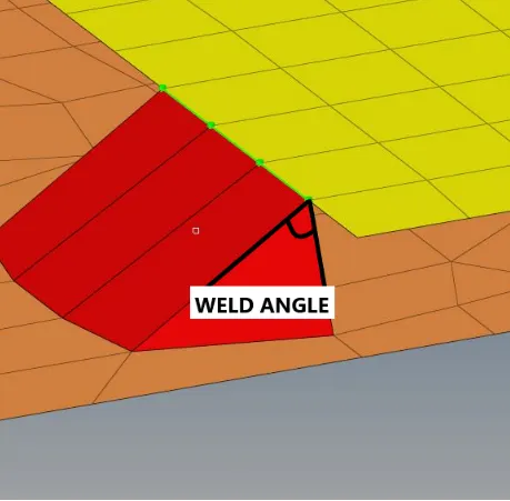
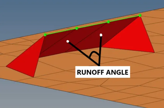
Runoff Angle:Angle between the normal of the first slant weld element and its adjacent weld elements.It is recommended to define weld angles between 0 and 10 degree.
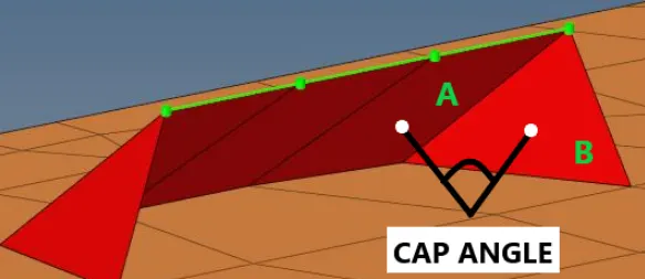
Cap Angle:Angle between the normal of the first slant weld element (A) and its adjacent side element (B). To define seam weld for 0 to 45 degree cap angle, it is recommended to select ≤10 degree and for the 45 - 90 degree cap angle, it is recommended to select ≥75 degree.
Right_Rail_2 & Front_truss_1
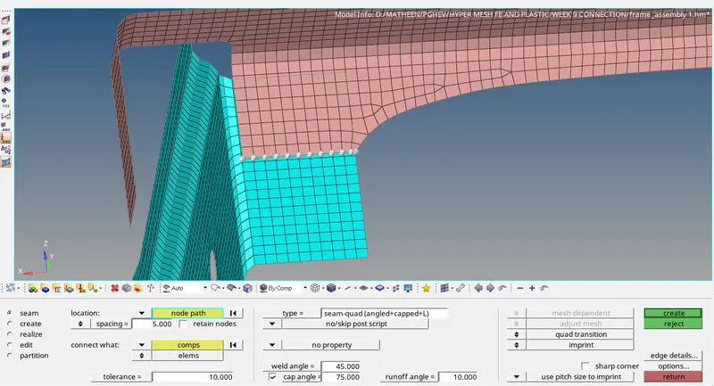
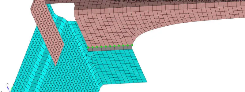
SEAM-QAUD CONNECTION IS REALIZED
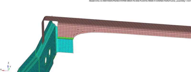
REMESHED FOR BETTER MESH FLOW
2. Quad elements:
Left_Rail_2 & Front_truss_1
Go to 2D >> Connector >> Seam >> Location: Nodelist (Select by path) >> Connect: Comps >> tolerence=10mm >> Type : Quad >> Quad transition >> Imprint >> Create
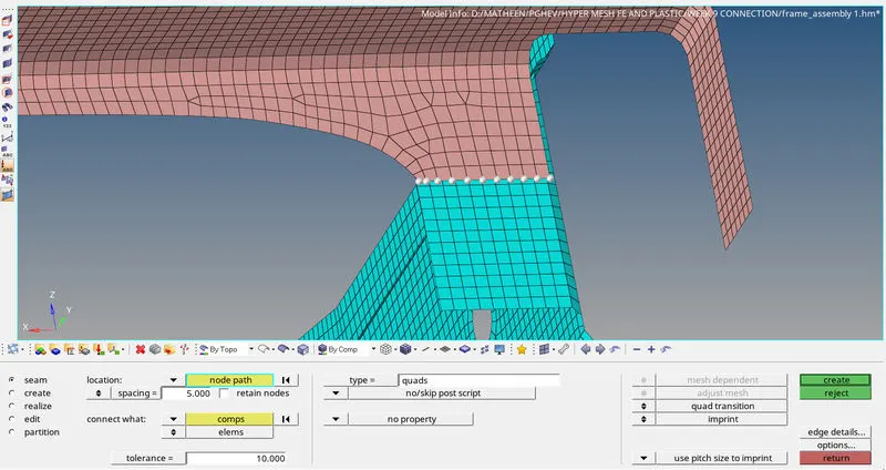
QUAD ELEMENTS
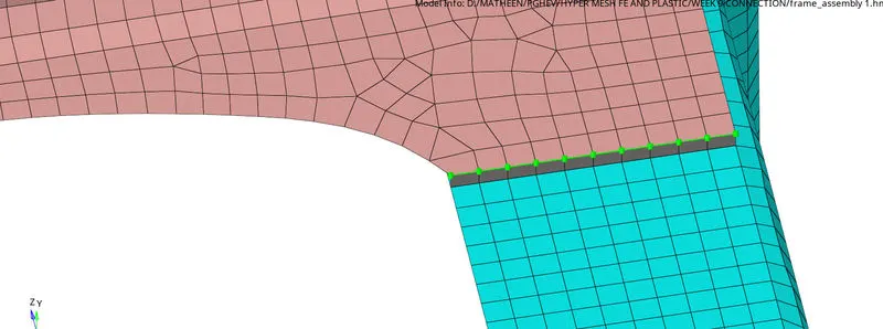
REALIZED
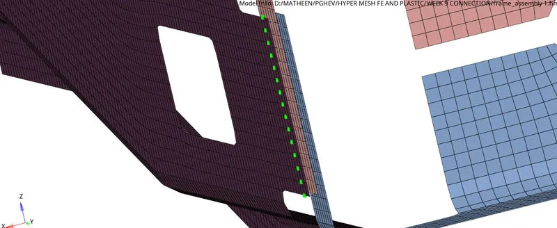
3. Spot weld with 3 Layers and 5 mm Diameter:
Front_truss_2, Front_truss_1 & Right_Rail_1
Go to 2D >> Connector >> Spot >> Location : Nodelist (Select by path) >> Connect : Comps >> Tolerence =10mm >> Type:Weld >> No. of layers =3 >> Diameter=5mm >> Create.
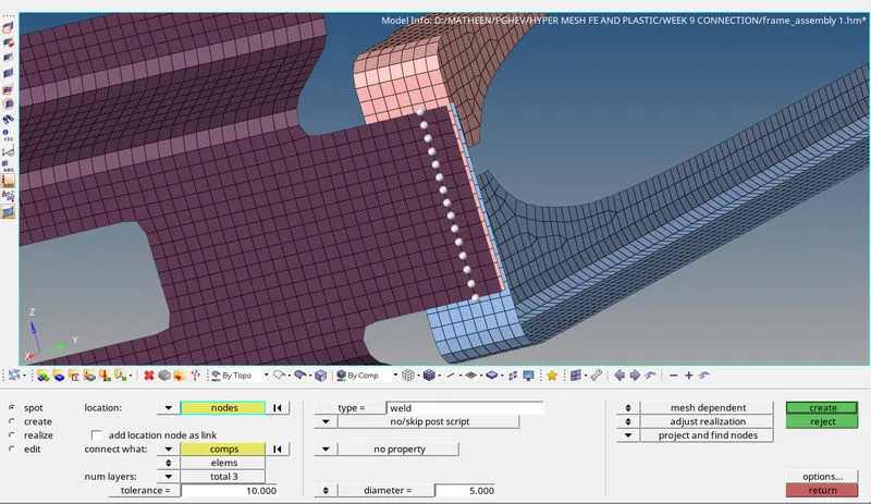
SPOT WELD
REALIZED
4. Hexa (Adhesive)
Front_truss_2, Front_truss_1 & Left_Rail_1
Go to 2D >> Connector >> Seam >> Location : Nodelist >> Connect : Copms >> Tolerence=10mm >> Type :Hexa(Adhensive) >> Strips =1 >> Coats =1 >> Width =1 >> Create
STRIP's known as thicknesss
COAT's known as width
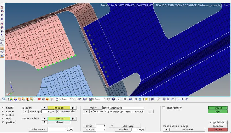
HEXA (ADHENSIVE)
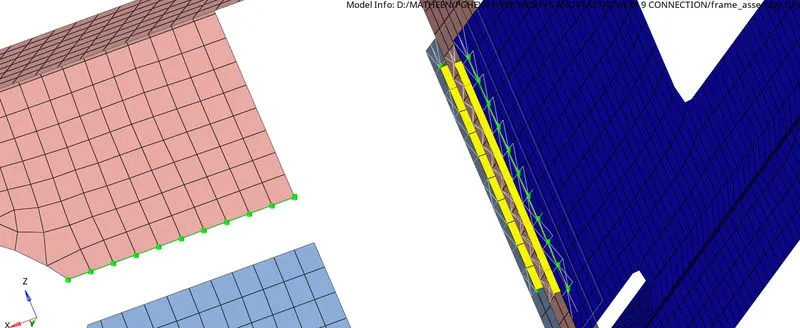
REALIZED
5. BOLT CONNECTOR'S:
Rear_truss_2 & Right_Rail_2
Go to 2d >> Connectors >> Bolt >> Location: Node list >> Connect: Comps >> Tolerence=10mm >> Type: Bolt (General) >> Create hole, If none >> Create
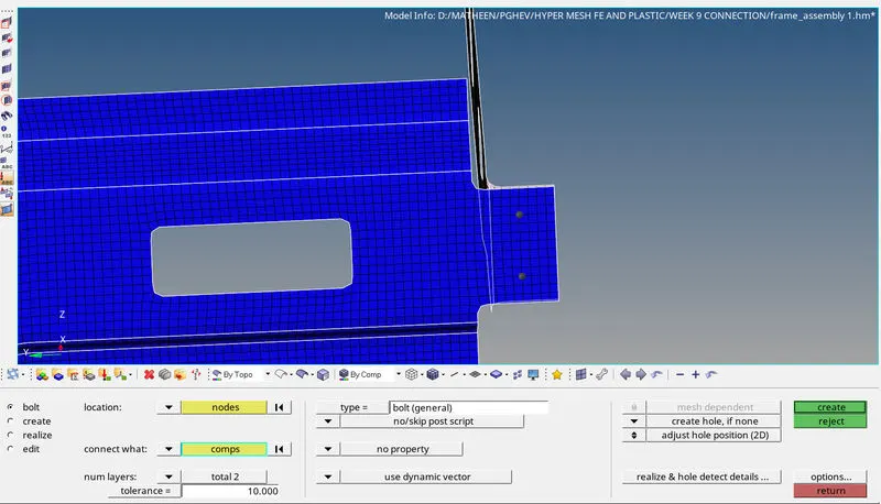
BOLT CONNECTOR
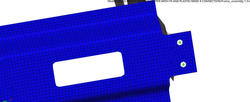
REALIZED
6. Rear_truss_2 & Left_Rail_2 : Same steps to be fallowed as above
7. Spot-weld with Rigid Elements:
Right_Rail_1 & Right_Rail_2
Go to 2D >> Connector >> Spot >> Location : Nodelist (Select by path) >> Connect : Comps >> Tolerence =10mm >> Type : Rigid >> Create
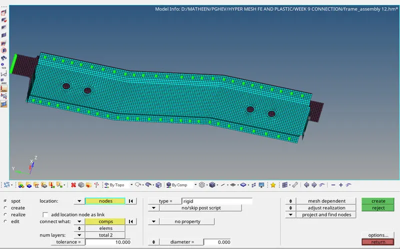
SPOT WELD WITH RIGIT ELEMENTS
8. Spot-weld with Rigid Elements:
Left_Rail_1 & Left_Rail_2
Go to 2D >> Connector >> Spot >> Location : Nodelist (Select by path) >> Connect : Comps >> Tolerence =10mm >> Type : Spring >> Create
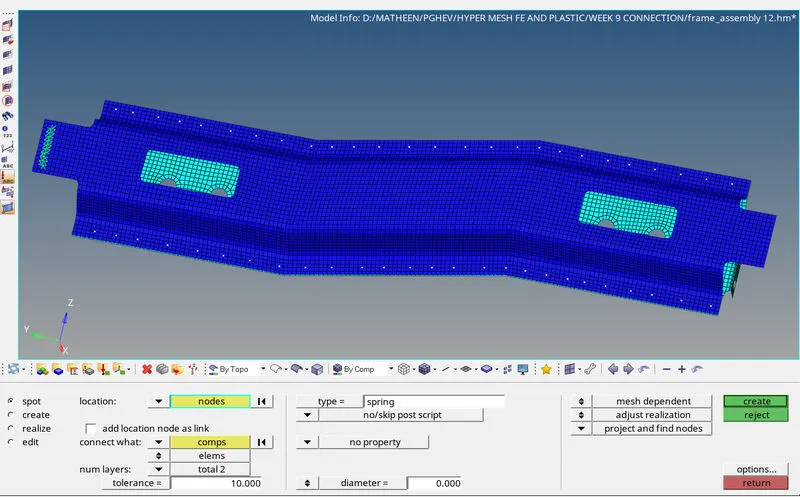
Spot weld with Rigid Elements
LEARNING OUTCOMES:
- Learned how to fix the geometrical errors to clean up the geometry.
- Learned how to create mid surface for each component.
- Learned how to meshed as per the given quality criteria.
- Learned how to reduce opposite tria's and rotating quads.
- Learned how to give connection Seam weld, Spot weld, Bolts etc.. .
RESULT: Given component is meshed with given element size and assemble this component with suitable connectors
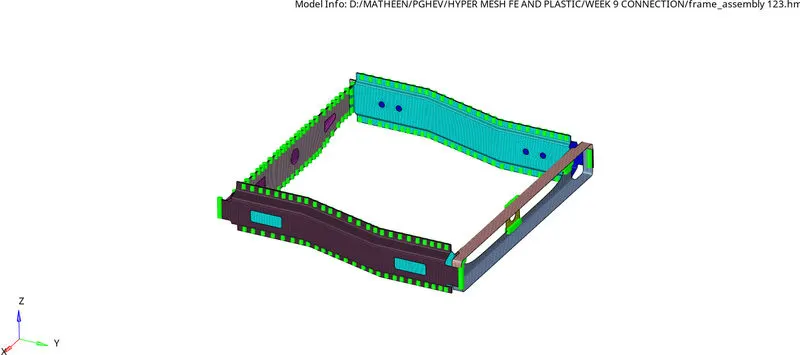
CONCLUSION:
I would like to conclude that here I learned various types of connectors and how to give connection for a given commponents