MORPHING TECHNIQUES BY USING ANSA
MORPHING TECHNIQUES BY USING ANSA
AIM : To perform basic morphing technique for the given CAD model
THEORY : Morphing is a design change terminology or morphing is use to change the design or shape of any component with or without any numerical input's.
EXAMPLE : Honda Brio (Hatch batch version) and Honda AMAZE (Sedan version of Brio) .
PROCEDURE :
STEP 1 : GEOMETRY CLEAN UP
STEP 2 : MORPHING
ADVANTAGE OF MORPHING
DIS ADVANTAGE OF MORPHING
RESULT
LEARNING OUTCOMES
CONCLUSION
In this model we get to know about how a model will be look like when design is change
It's required lot of time effort etc..
Morphing can be done in many ways but here we are using only FREE - FREE morphing method its a basic step of morphing
Here we just morph the given CAD model at any direction we want so that it giving a new shape and new size
So to do that iam importing my given cad model and clean up the geometry then iam going to try out basic morphing techniques in this component
STEP 1 : GEOMETRY CLEAN UP
Import the given CAD model into ANSA
FILE >> OPEN >> CAD MODEL
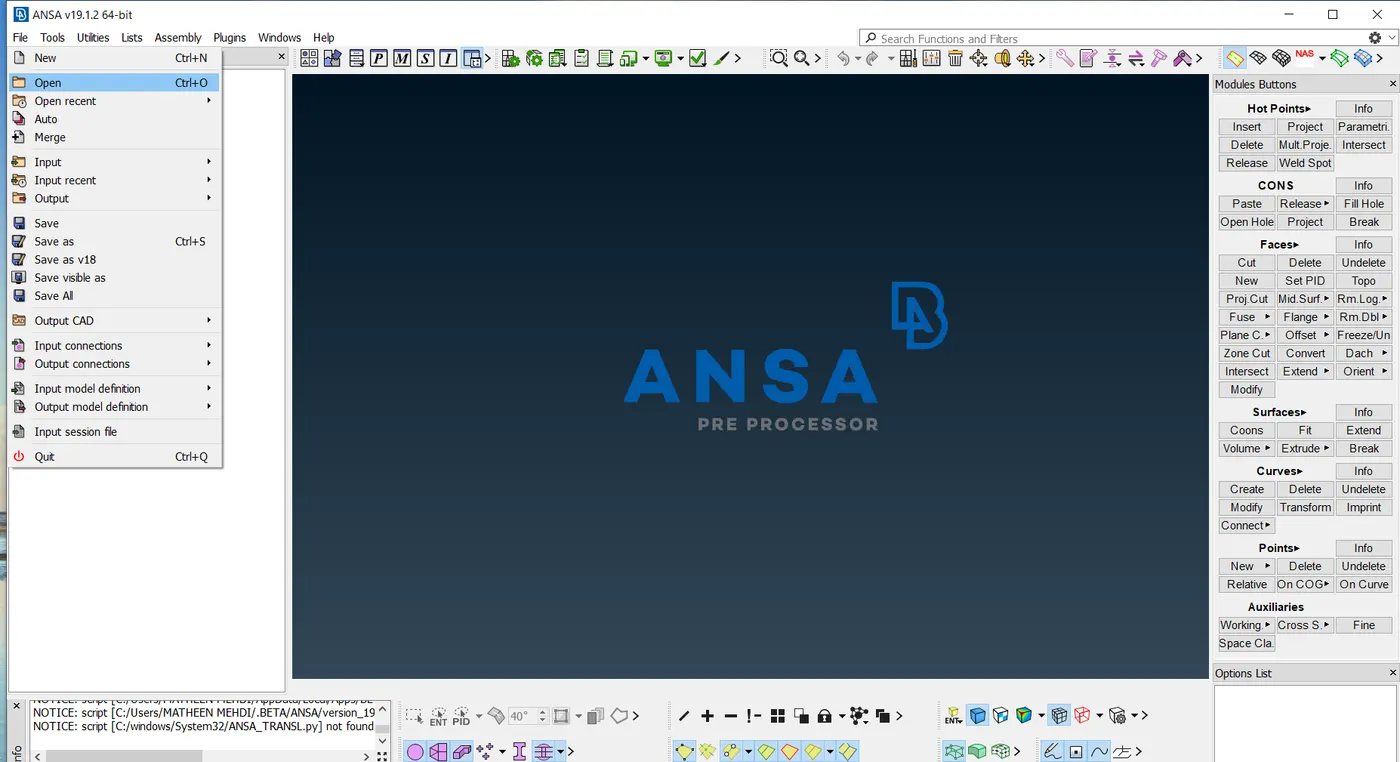
IMPORTING CAD MODEL
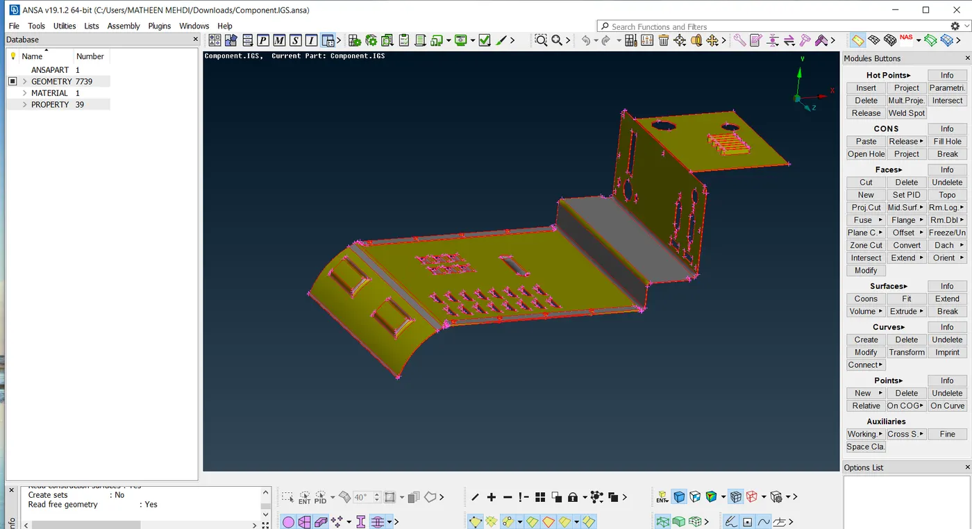
MODEL IS IMPORTED
Now check the model for geometry check on top of commands select geometry check. this displayed some errors of triple cons
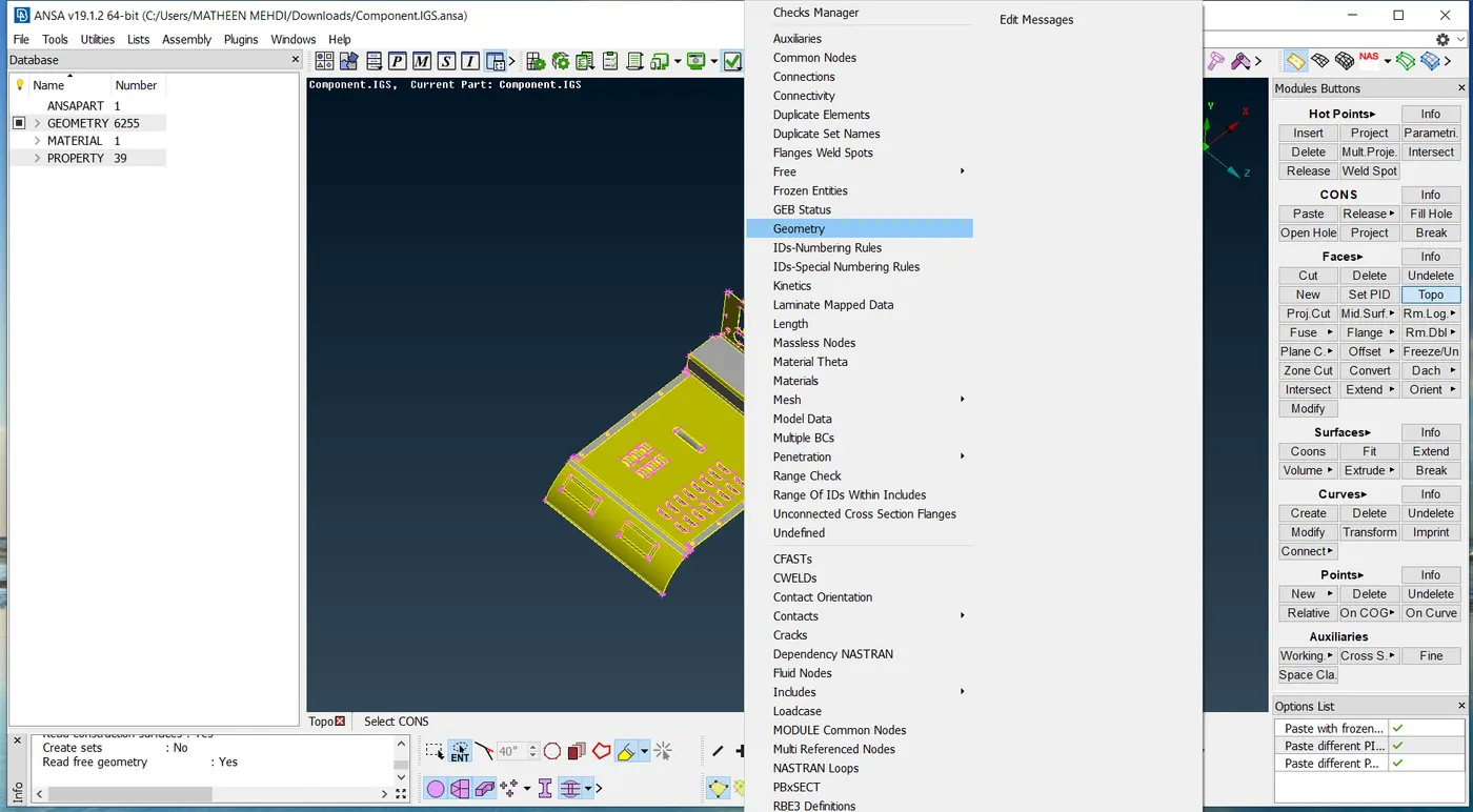
GEOMTERY CHECK
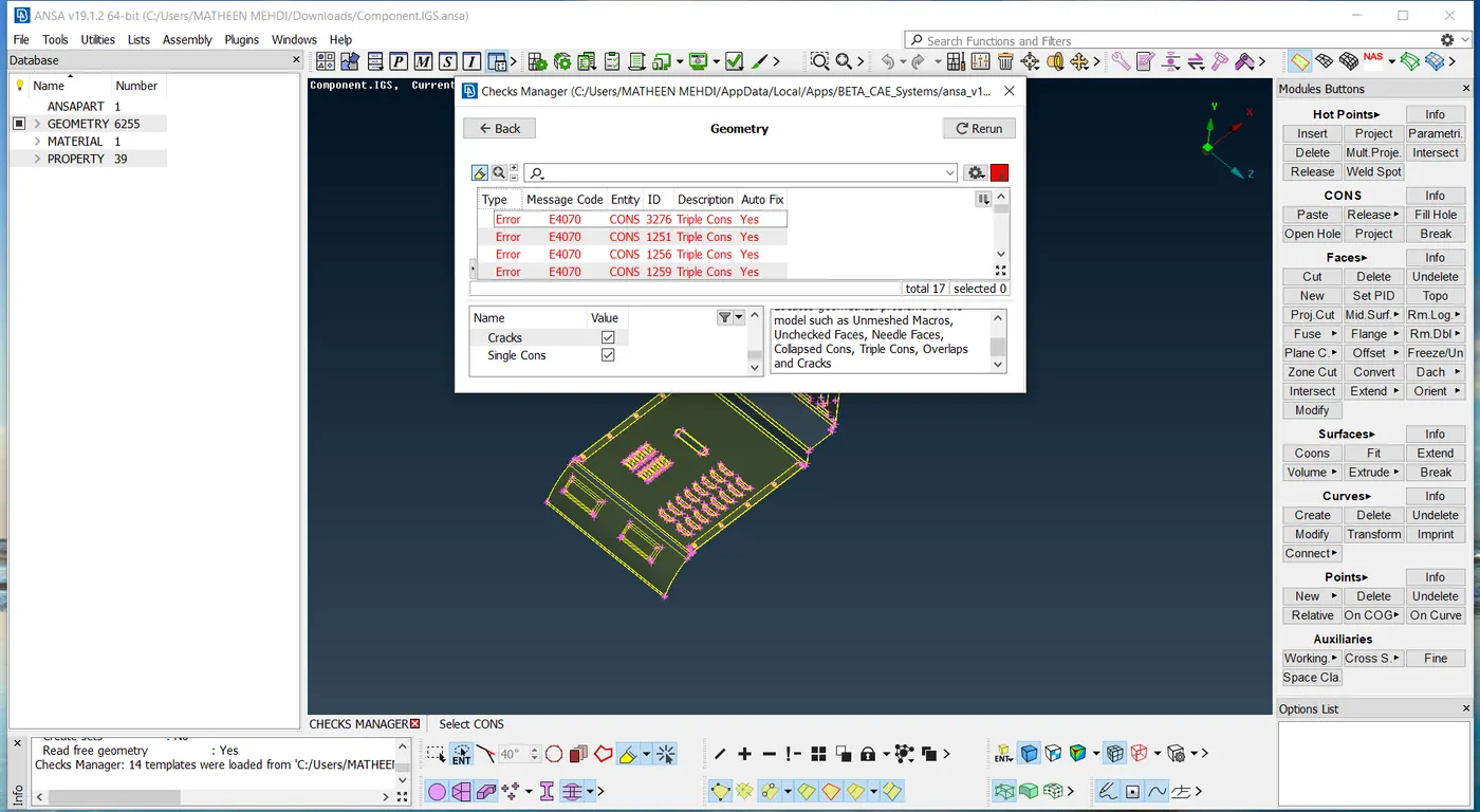
ERROS
Here we need to fix those errors by using contrl A then right click and fix
Still we have some errors of triple cons here we need to fix those errors by manual method by using cons release under topo
TOPO MODE >> CONS >> RELEASE
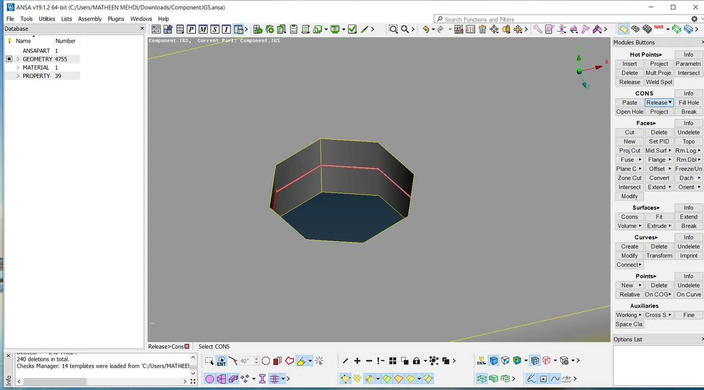
RELEASE OF TRIPLE CON
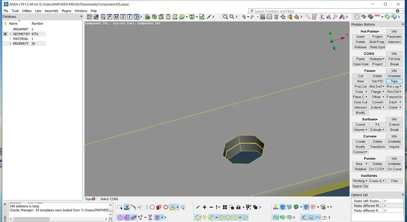
APPLYING TOPO
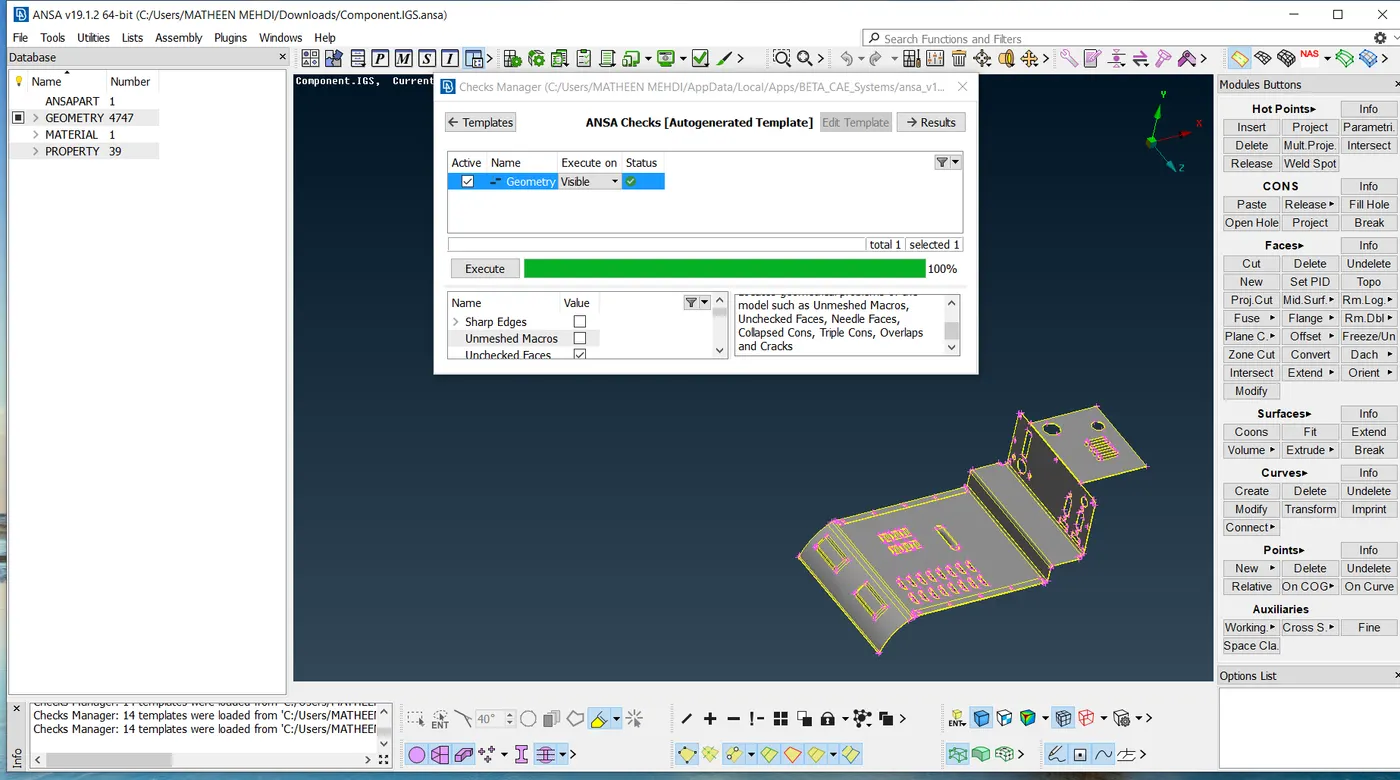
ERROS ARE FIXED
Now the erroe are fixed we can proceed for morph techniques
Before move to morphing mode first set the proper orientation and change the perimeter length to 1mm
MESH MODE >> PERIMETER >> LENGTH >> 1mm
STEP 2 : Morphing
First delete all bolts and nuts
select the face where to morph then goto morph mode
Here we can see boxes under morph module buttons
Select new
Under new the sub option called ortho then select geometry select the face by box selection
MORPH MODE >> BOXES >> NEW >> ORTHO >> GEOMETRY
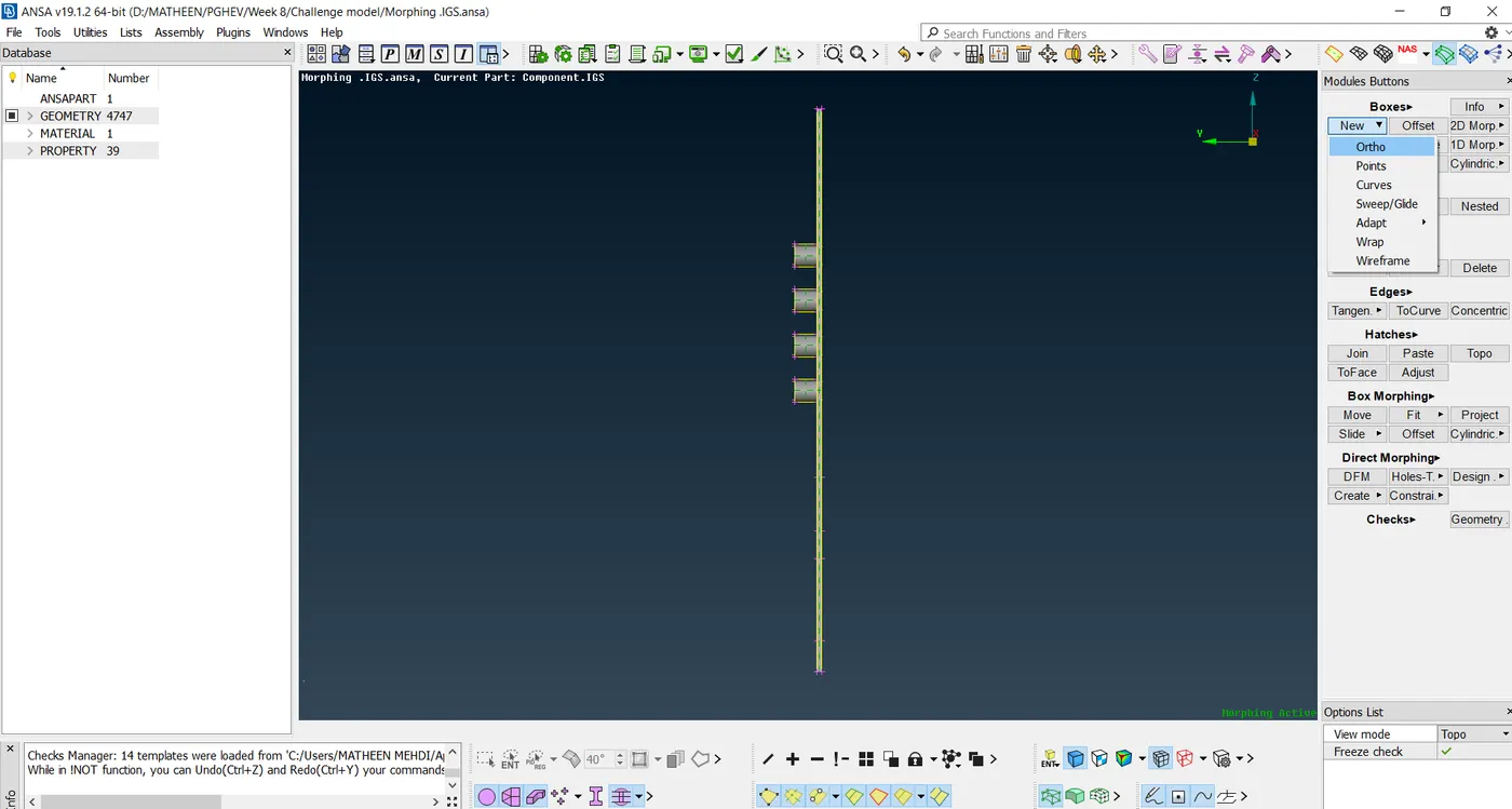
CAD MODEL
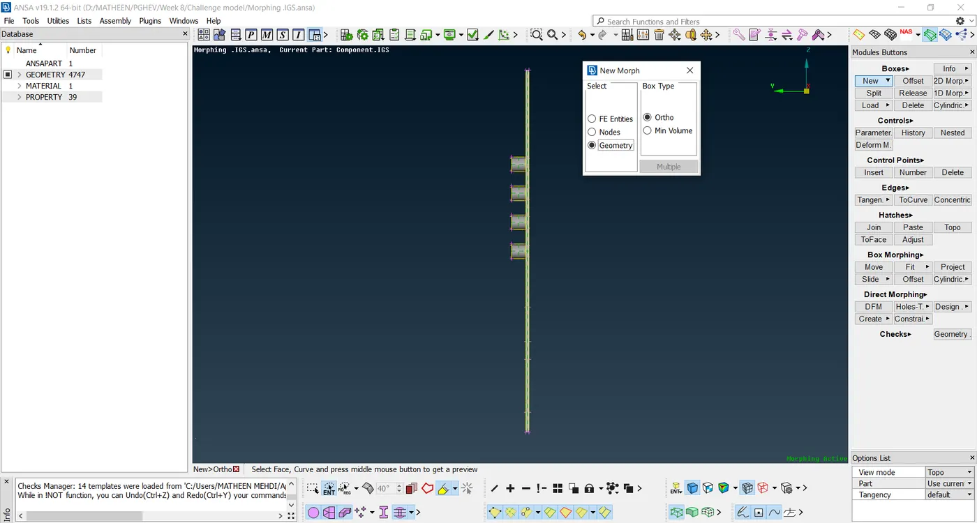
NEW MORPH BY GEOMETRY SELECTION
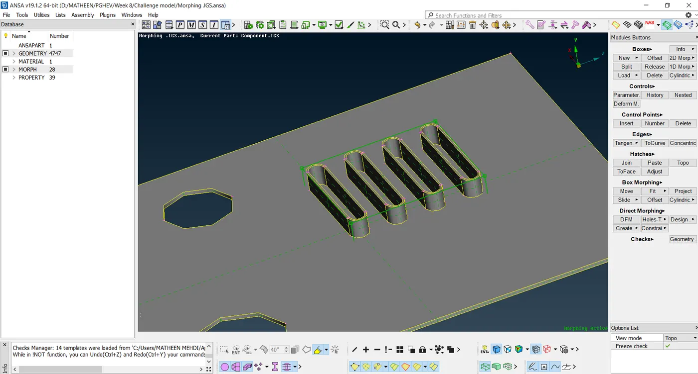
MORPH BOX CREATED
Now i have created a morphing box
This morphing box have control grid so this box move along the control grid only
Control grid can be moved by numerically or by our panel input this based on the global co-ordinate
If you want a loacal co -ordinate can also be made by right clicking in mouse anywhere inside the morph window
Now i want to increase the size of the CAD by specific measurement
Here the intial measurement of CAD is 10mm and plate thickness is 2mm
So now total height of CAD is 12mm
Now change the size of CAD
MORPH MODE >> BOX MORPHING >> MOVE >> SELECT NODES or ENTITIES
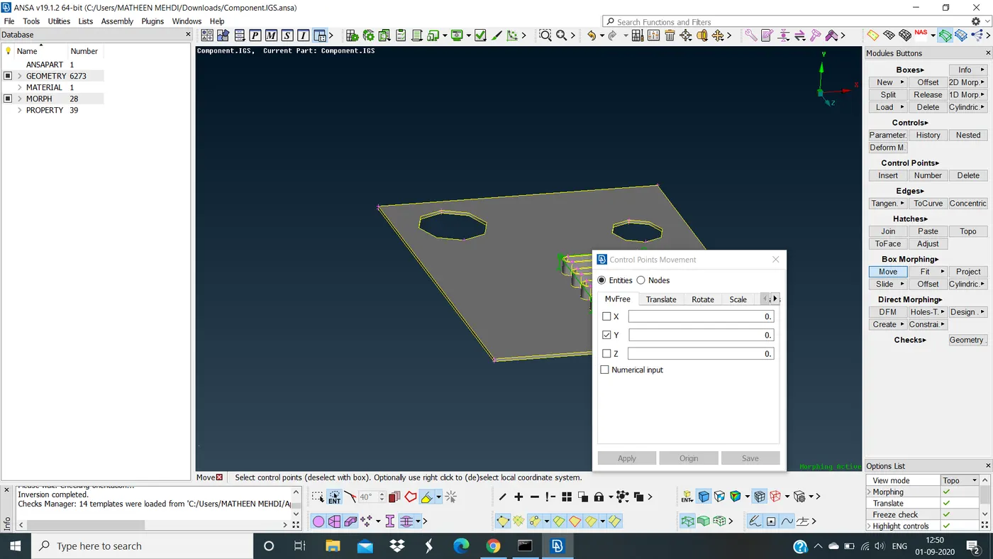
SELECTION OF NODE
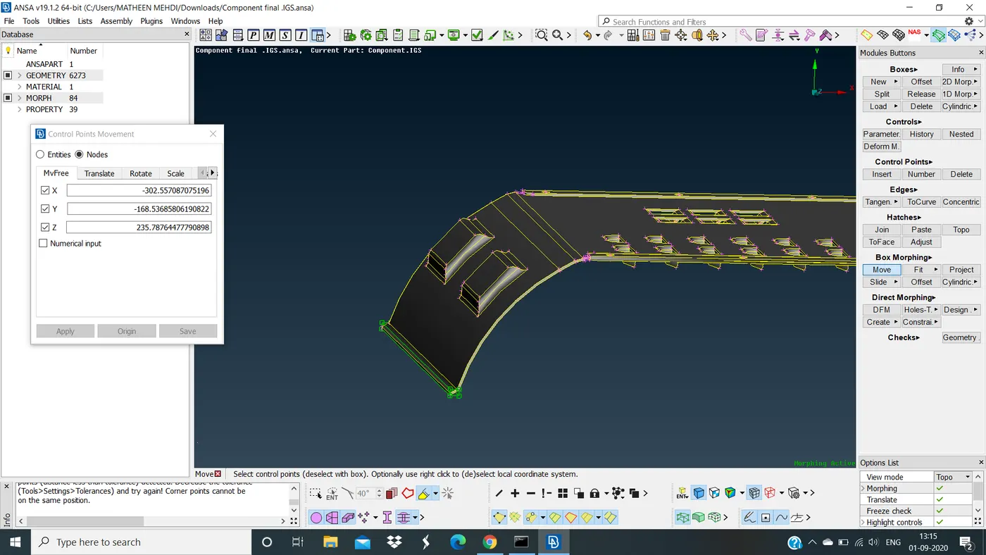
Now i will Reshape my morph by selecting node to move along the Y-direction
Now you can see the size of CAD is increased this will give an idea of how it will look like when its increased
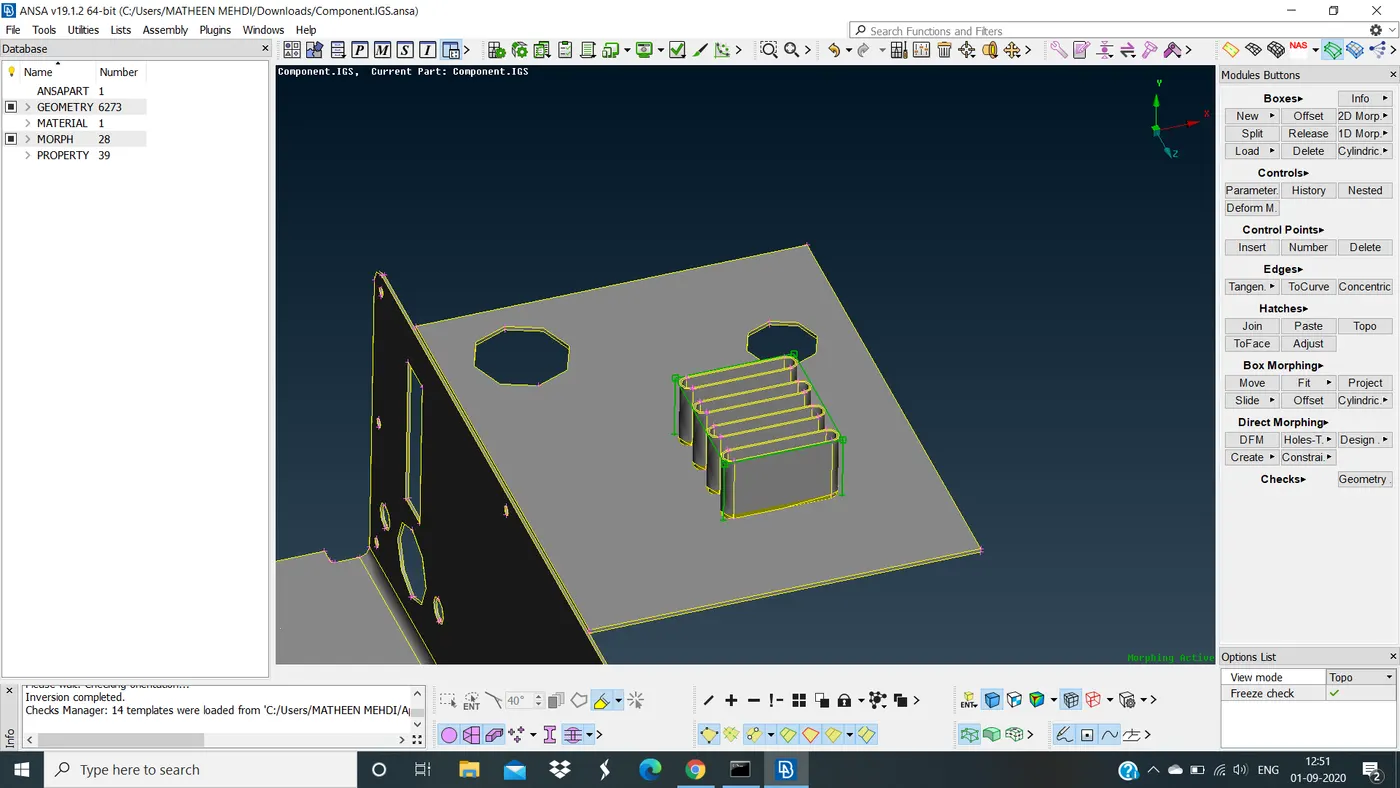
RESHAPE THE SELECTING PART
Morphing might give some distrubance on the CAD model but it will definitely tell you how the component would look like when it has to be morph
Now again i will select new by box selection >> ortho create box and move along nodes that has to be selected
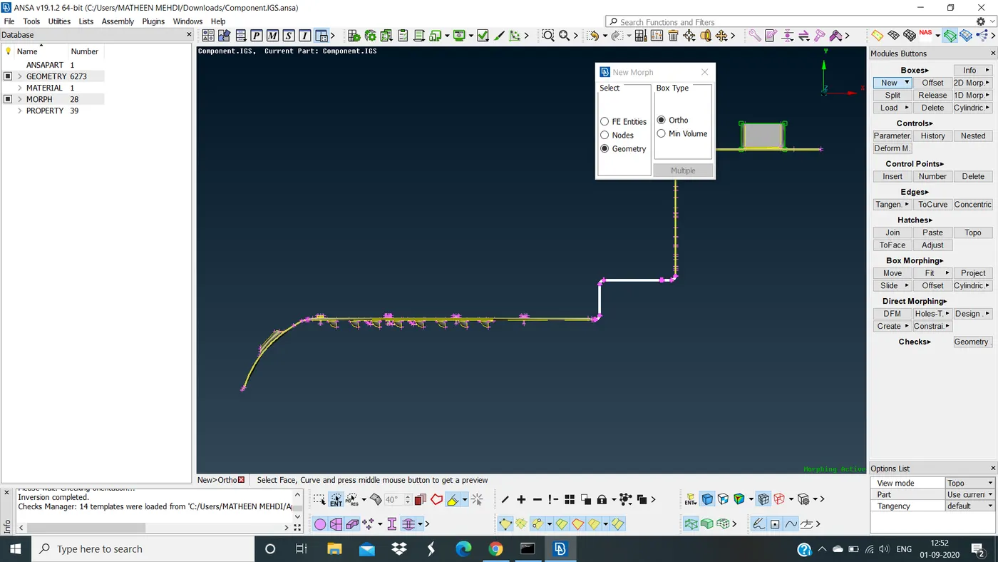
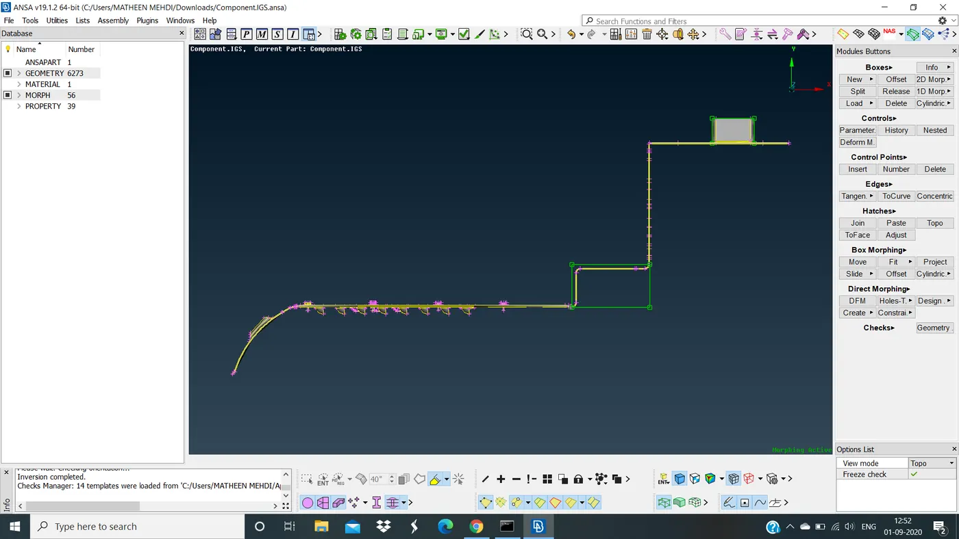
CREATED A MORPH BOX
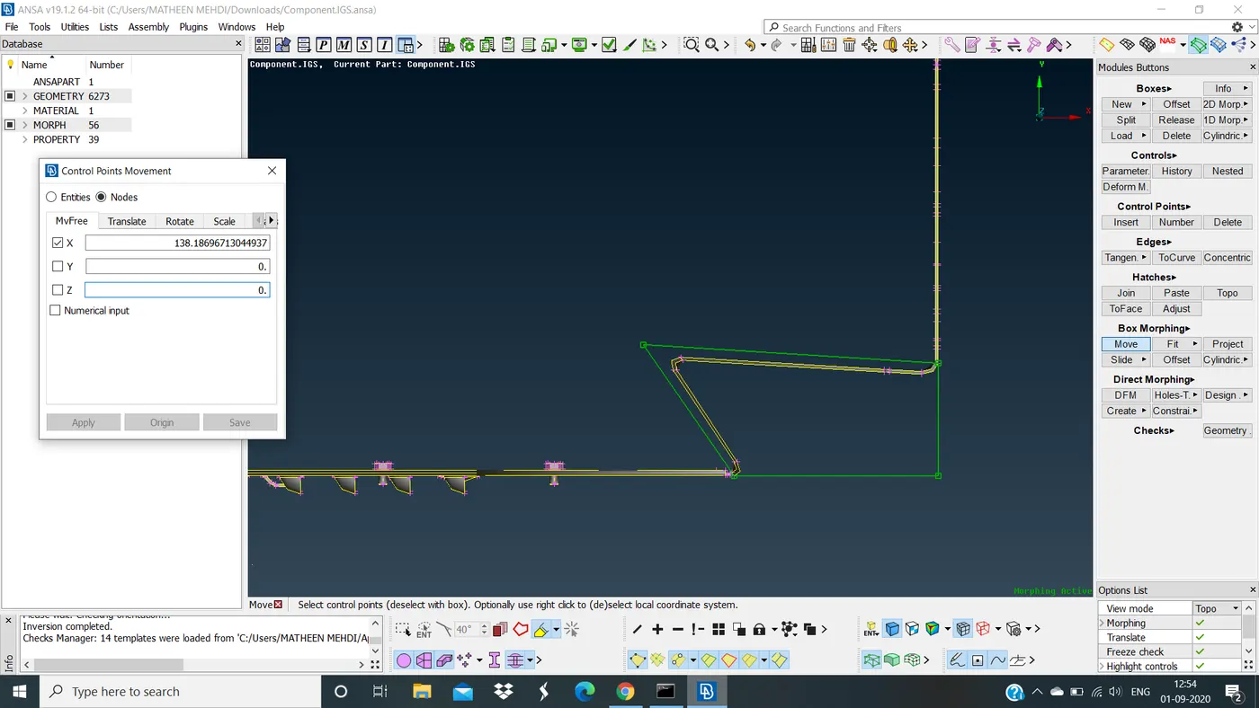
RESHAPE THE SELECTED PART
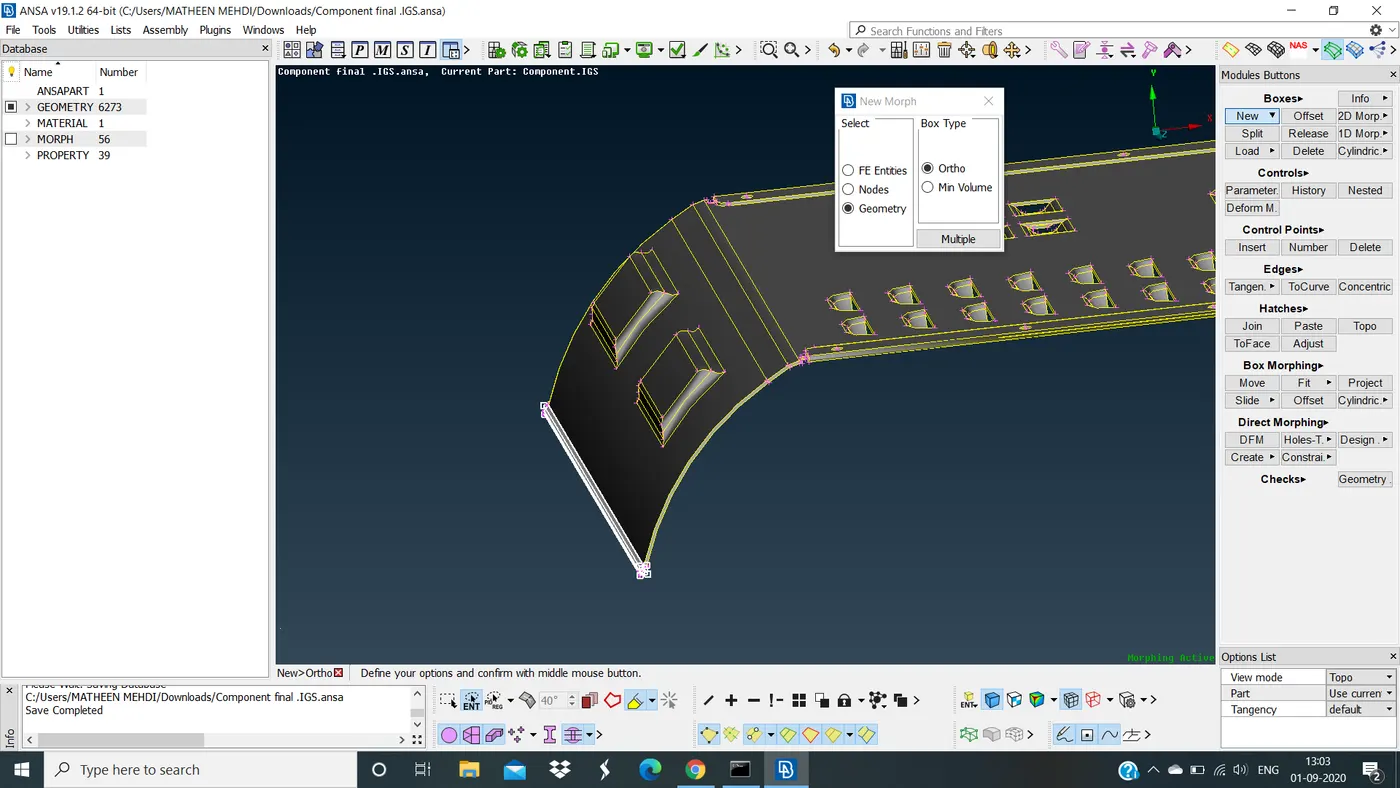
Now again select different face to morph by using morph box here we are selecting full CAD component as a box selecion in which we can project hot points of CAD model to the morph box so it will form a split boxes as shown below
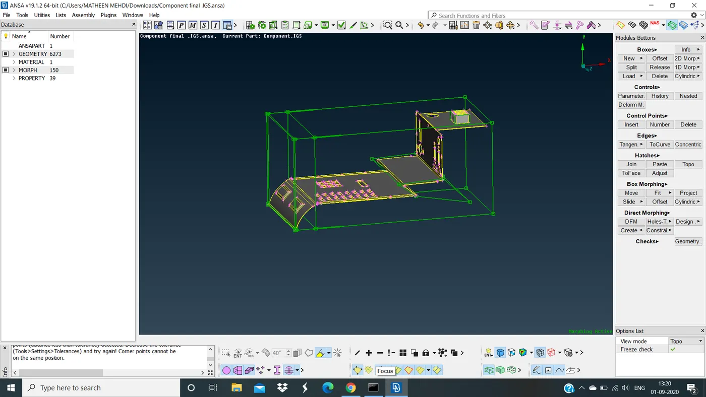
SPLIT BOX WILL CREATE
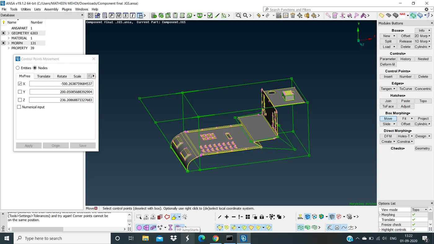
RESHAPE OF SOME MORE COMPONENTS IN THE MODEL
OFFSET :
For offset we need to select the CAD part that have to offset
Select by box selection >> new >> geometry >> set the part >> middle click
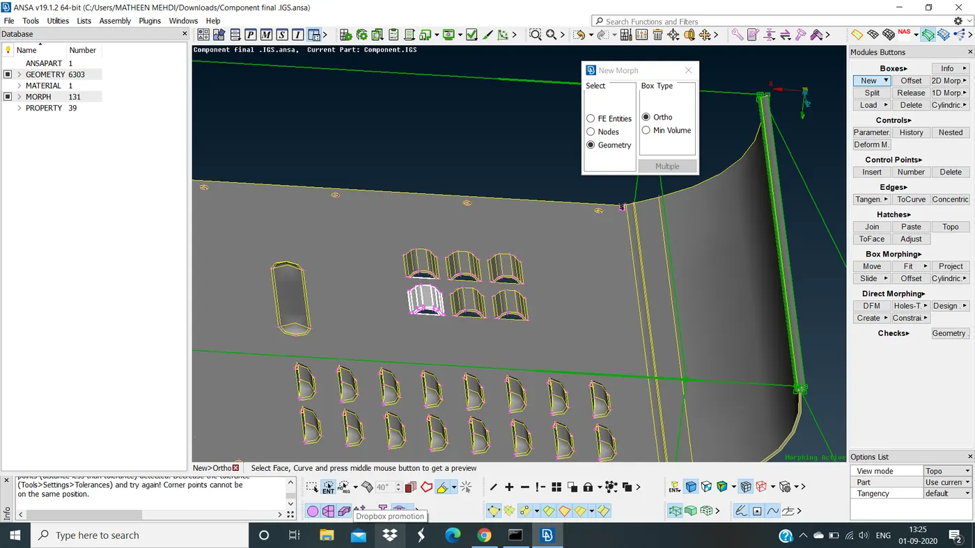
SELECT PART TO OFFSET
Now create a morph box
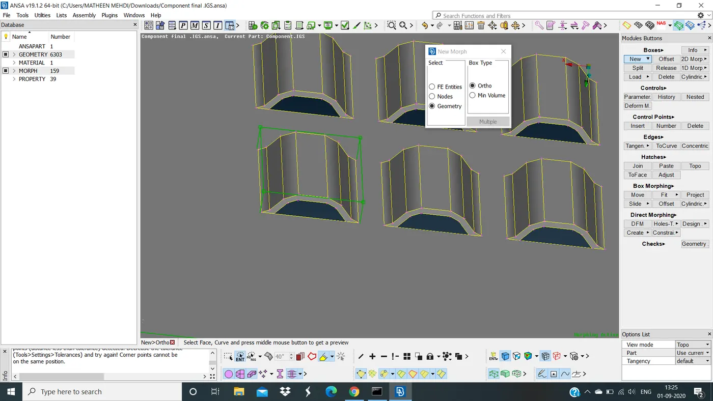
MORPH BOX CREATED
Now goto offset under box morphing give a value and slide the needle as shown in below fig
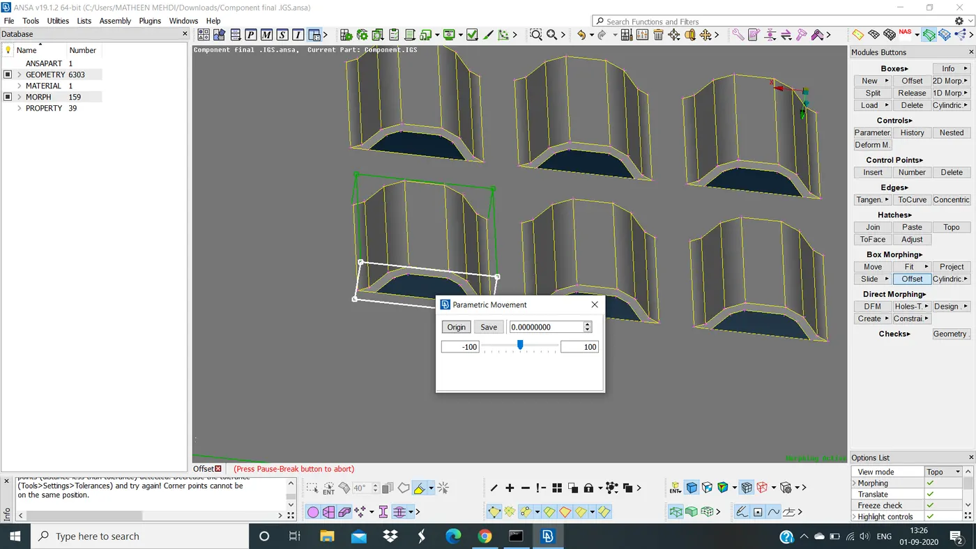
OFFSET PARAMETRIC MOVEMENT TAB
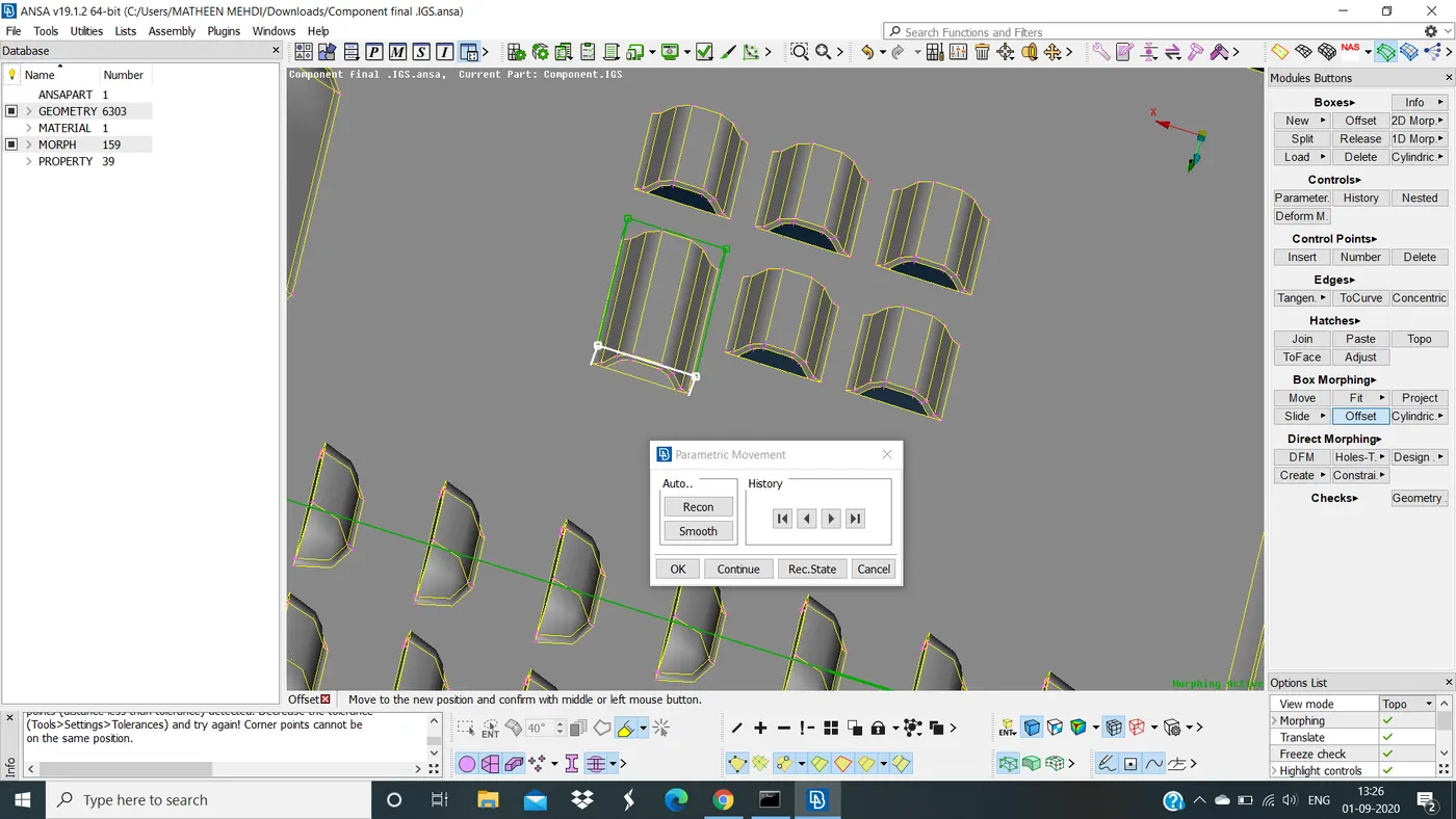
FINAL OFFSET PART
Now select any one identical face in CAD model
Create a morph box to the selected face and move the face
Then reshape that part as shown in fig below
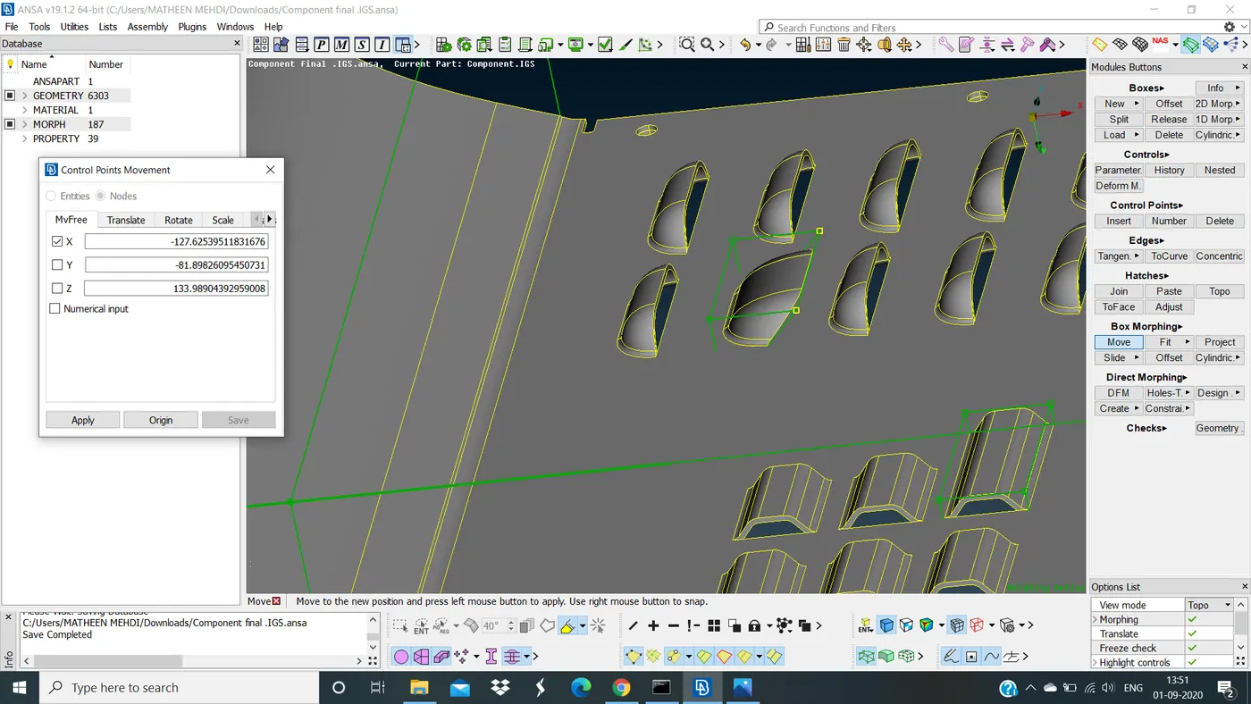
MORPH BOX CREATED
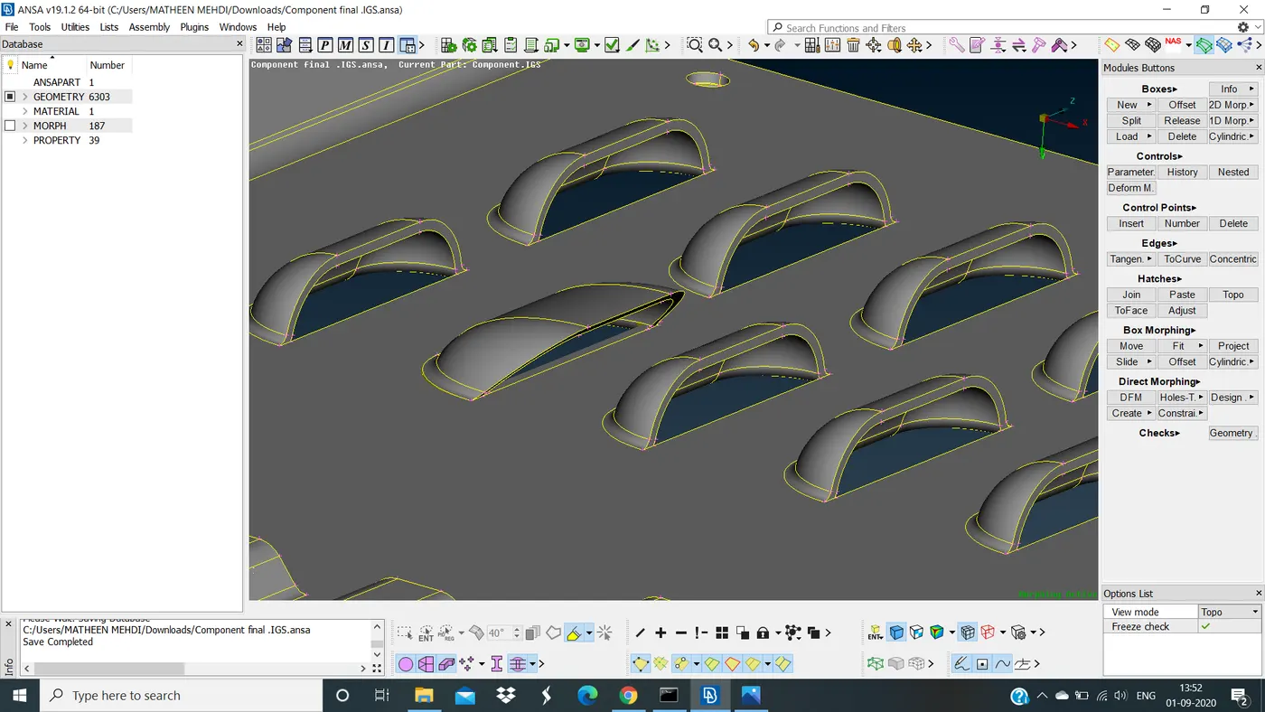
REMESH OF SELECTED IDENTICAL PART
This is easy and simple method
This is one of the method that combination of simple and complex morphing method where introduce to make those design changes for a given model
For this required a lot of knowledge and idea to work on the model
This give an engineer to freedom to change the design upto the extend that he want to be change
In morphing any type of change of shape can be done
ADVANTAGE OF MORPHING :
It can be worl on both CAD and FE model.
DISADVANTAGE OF MORPHING :
It will give some disturbance to the given model.
RESULT : Morphing techniques done for a given CAD model
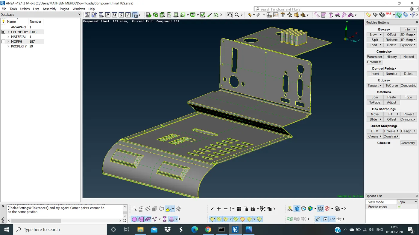
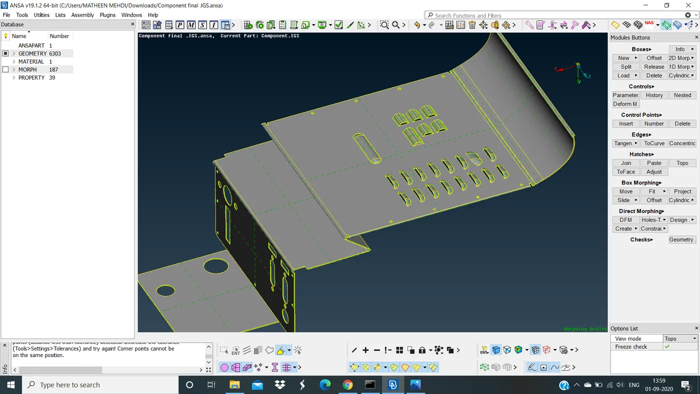
FINAL MORPH MODEL
LEARNING OUTCOMES :
- Learned how to do basic of morphing techniques .
- Learned how to create a morph box .
- Learned how to move morph box by selecting entities or nodes .
- Learned how to change the design of given CAD model .
- Learned how to offset under morph mode .
CONCLUSION :
Successfully performed basic morphing technique for a given CAD model and reshape or change in design has been done.