Week 9 - Challenge 1 - Base Bracket Design
AIM: Create the tooling axis for the given Base Bracket model meeting the requirements of the draft angle and perform the Draft analysis on the model.
- Import CAD file.
- Class A Surface
- Tooling Axis
- Publication
- Free Form Analysis
PROCEDURE
- Import the given BASE BRACKET - IGS file into CATIA V5 and Save it.CATPart.
Class A Surface
The Class A Surface of the BASE BRACKET is defined in the Geometrical Set. 1. Here we can see that the surfaces of the given CLASS A SURFACE are not topologically connected. In order to do that, select the Geometrical Set. 1 and perform a Join operation.
Tooling AXIS
In order to create a Tooling Axis first we have to analyze the given Geometry. The Tooling direction we create determines the clearance on all the faces of the geometry. So that there won’t be any issue while ejecting the part from Core and Cavity. By analyzing the geometry we know that the clearance of tooling direction is on the Z Axis. In order to create a Tooling axis we need a point definition and Axis System. Create a Boundary using the center hole then plot a point and insert an Axis System.
PUBLICATIONS:
Before the Draft Analysis, we have to publish both the CLASS A and Tooling Axis.
After creating the tooling axis and publication creates a class B surface for the given geometry. To create it we need to use different commands like Extract, Surface Untrim, Extrapol, Trim, and Offset based on the geometry.
After creating the class b need to do the class c surface here we need to use the boundary and sweep command. Based on the direction we need to use a sweep. After needs to join Class A and Class C by using the join command. Finally need to trim from class B to join.
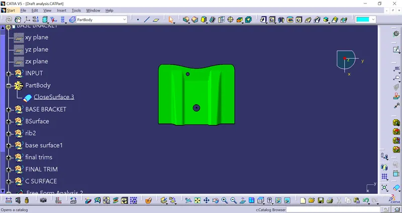
Define part body and generate a close surface.
Free Form Analysis
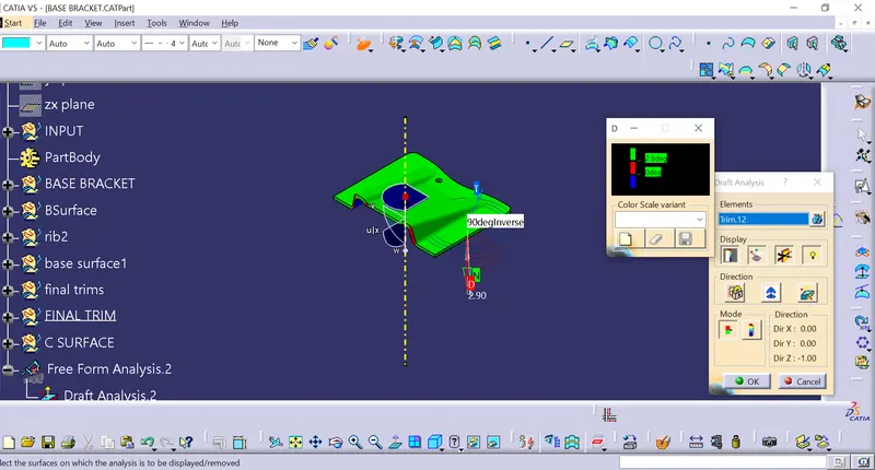
Free-form Analysis is done to ensure the part we drafted is easily removed from the Core and Cavity. In order to do that Go to Insert > Analysis > Feature Draft Analysis. Now Draft Analysis popup appears. There is a direction section that selects the compass to define the draft direction. Drag the compass and place it on the Tooling Axis direction, then lock the draft direction. Now select the Class A Surface which shows the positive and the negative angles in two different colors. Green is the Positive angle and Blue represents the negative angle. The third one is red which represents an angle closer to 0 degrees. The Draft Analysis is performed by specified values. So we have only positive and negative angles with that finally we come to a conclusion that we have a proper tooling direction.