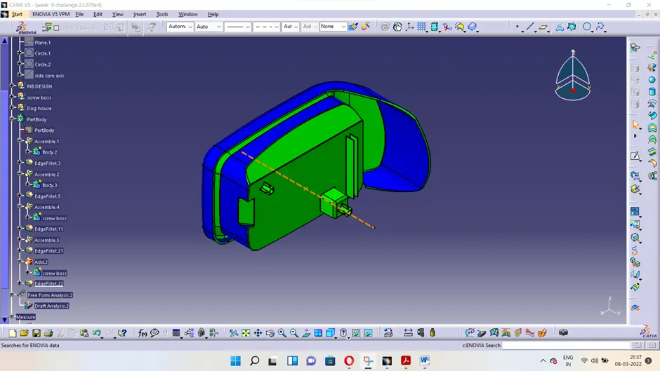
Week 9 - Attachment Feature Creation - Challenge 2
SCREW BOSS AND DOG HOUSE DESIGN FOR COIN HOLDER
Screw Boss Design:
- For screw boss design, extract the bottom surface, take a point at its centre and draw a sketch as shown below for the cylinder part of screw boss.
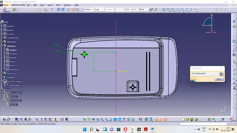
- We have considered a screw boss for M6 screw here. Hence, the hole diameter 5.2 mm. As the screw boss thickness should be about 40% or less than that of the normal wall, we take screw boss outer diameter to be 7.2 mm. (5.2 + 1 + 1)
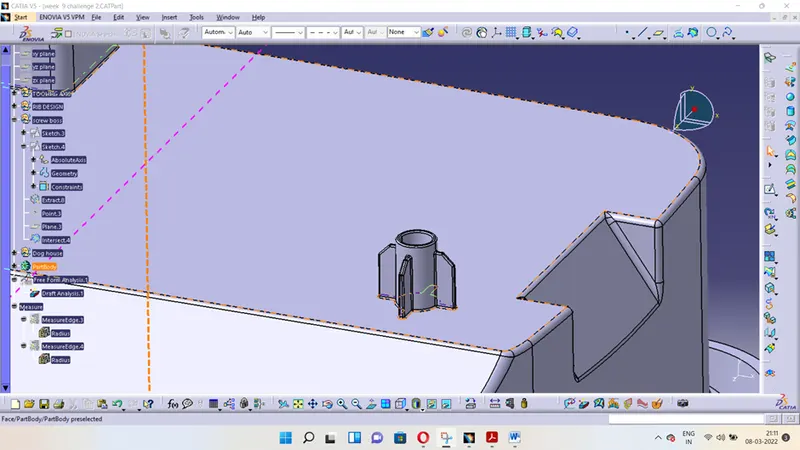
- Then, extrude the cylinder by using Pad command up to 15 mm, as the hole diameter is 5.2 mm and the height to diameter ratio should be 3:1.
- Then we need to draft the inner as well as outer wall with respect to tooling axis. At least 0.5 degree of draft angle should be provided on both the walls.
- After that, for the rib part we can copy and paste the same sketch before and use that to sketch as shown below.
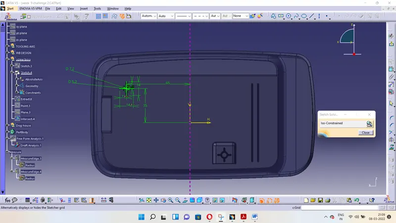
- Using Pad command extrude the sketch and thicken it by 12 mm and then apply draft to all the vertical walls of the ribs as described above for cylindrical walls.
- Now apply fillet of 0.25 mm (which is the maximum allowed radius) to the edges.
Dog House Design:
- For dog house, take a sketch on the bottom surface as shown below.
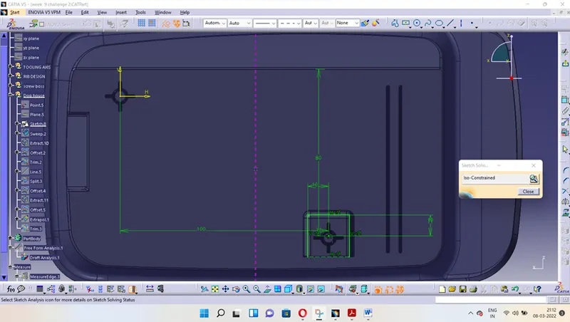
- Now, sweep the sketch with a draft angle of 1.5 degrees along the tooling axis by 21 mm. 1 mm additional for trimming convenience later on. Then offset the base extract upward by 20 mm and trim with the sweep to get trim output as shown below.
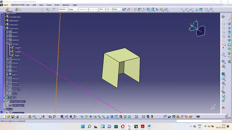
- After that thicken this trim outward using thick surface command by 2 mm.
- Then, use the back vertical wall to offset and split the front section of dog house to get a proper edge.
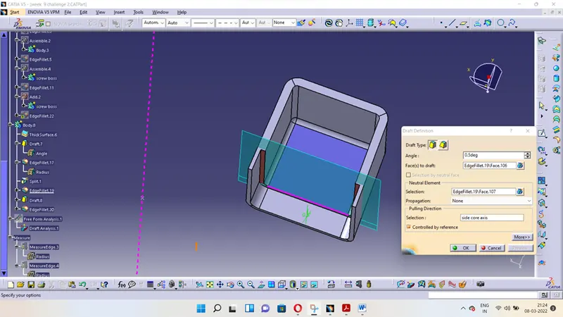
- Now, we need to get the side core tooling axis as the dog house will not be cleared in mold ejection through main tooling axis. Take a point anywhere on the base surface (below the dog house for easier access) and take a line through this point parallel to Z axis.
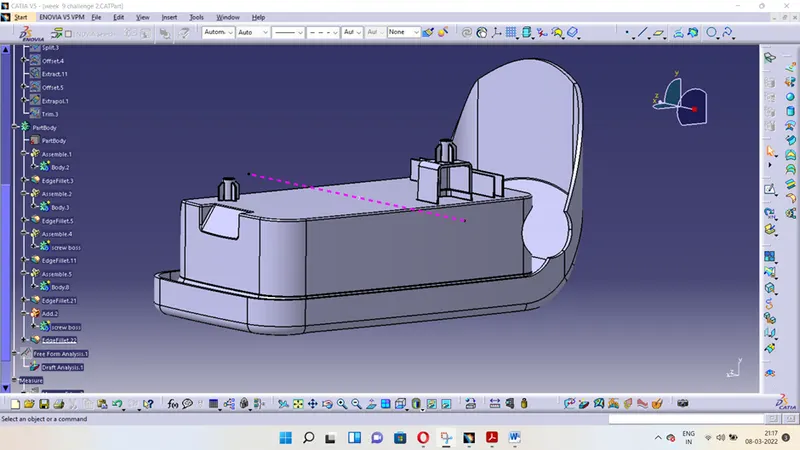
- This will be our side core tooling axis. Now provide draft to the inner walls with respect to this tooling axis as shown below.
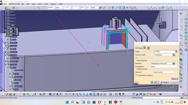
- For the step portion, offset the previous trim outward by 1 mm and the base extract upward by 4 mm. Then trim them to form the output as below.
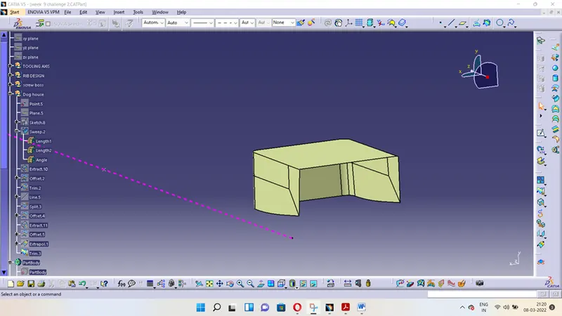
- Now, use this trim to split the thickened solid body to form the dog house step as shown below.
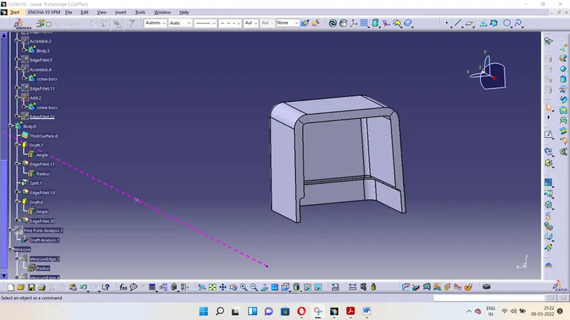
- We can apply fillets to the edges now.
- We need to make sure that the portion below should also be provided draft along the side core tooling axis.
- Then, we can add the part with main body using boolean assemble operation.
- Now, if we want a screw boss on top of the dog house, we can translate the screw boss. Copy and paste the initial screw boss body. Then translate it using Translation command to the appropriate point using coordinate values.
Draft Analysis and Colour Scale Variant (Without Bosses and Doghouse)
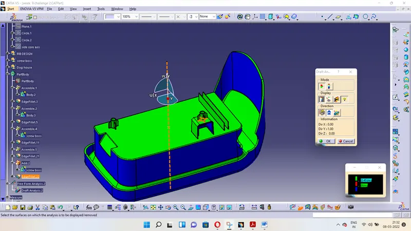
As it can be seen above, the screw boss is easily cleared at 0.45 degrees as the draft angle for screw boss walls is 0.5 degrees.
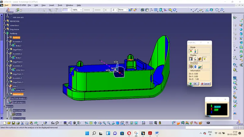
The dog house outer walls are cleared along main tooling axis at 1.45 degrees as we’ve taken draft angle as 1.5 degrees for the dog house outer walls along main tooling axis.
Model different views
Front view
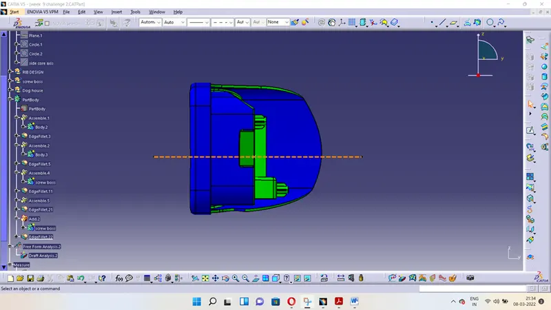
Side view
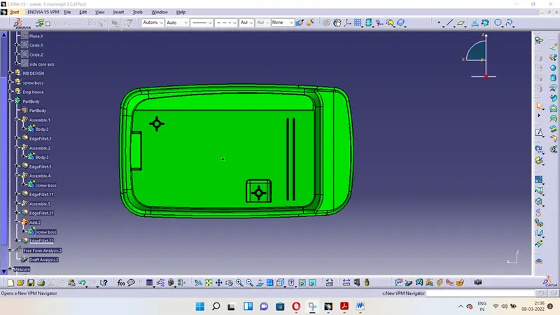
Top view
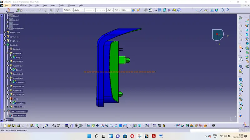
Isometric view