Week 8 - Challenge 2 - Base Bracket Design
AIM:
Create the Base Bracket Plastic component through the given Class-A surface. And perform the Draft analysis on the model.
OBJECTIVES:
To model a base bracket and perform draft analysis on the model.
THEORY:
Draft Analysis:
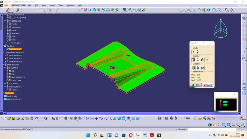
Draft analysis helps to detect if your drafted part is easily removable from the mold (in case of plastic component) or die (in case of sheet metal). All plastic components will have a minimum draft of 0.5 to 3deg. And for automotive sheet metal parts the draft will be 7deg or more. If a mold wall is perpendicular to the part ejection, there is ample friction or interference between the mold and the part which will not allow one to release from the other. This is why design engineers give a minimum draft to the part.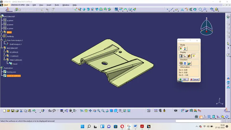
Mode:
- The mode option let you to choose between quick analysis and full analysis mode.
- In quick mode there are 3 ranges with blue, red and green colors. In case of plastic component we will set the draft angle as 3deg.
Display:
- The first box is to open and close the colour scale dialogue box.
- The second box is the analysis under running point, when activating the checkbox and moves the pointer over the surface. This option enables you to perform a local analysis. Arrows are displayed under the pointer, identifying the normal to the surface at the pointer location (green arrow), the draft direction (red arrow), and the tangent (blue arrow). As you move the pointer over the surface, the display is dynamically updated. Furthermore, circles are displayed indicating the plane tangent to the surface at this point. The displayed value indicates the angle between the draft direction and the tangent to the surface at the current point.
- Click the No Highlight Representations button to set the display option of highlight effect sources as "on/off". When checked "On" the surfaces are selected but they will not be seen in the specification tree.
- Click the Light Effect button and the colours of the analysed elements react to the light source
Direction:
- The first check box is locked direction icon which is used to lock the direction of the compass after selecting the specified direction.
- Click on compass icon to specify the new pulling direction to remove the part.
- Click the Inverse button to automatically reverse the draft direction. When several elements are selected for analysis, the draft direction is inverted for each element when the button is clicked.
Tooling Direction:
The Tooling Direction is basically the direction that the mold pulls apart. The mold is built in two separate pieces, basically. You have a Cavity side and you have the Core side. The Core pulls apart from the Cavity and that's the Dyeline or the Tooling Direction. There are different methods to find out the tooling direction. Here we are using bisecting method to find out tooling direction. We can use any method the ultimate aim is to reduce the cost of manufacturing by reducing the complicity in manufacturing the component.
PROCEDURE:
The procedure is divided into two parts first creating the tooling axis then performing the draft analysis.
Creating tooling axis using bisecting method:
- The first thing to do is finding out the possible tooling direction by visually checking the part. Rotate the part in all direction and find out most suitable direction for tooling. Here in this case viewing from Z direction we can clear the face in tooling.
- Then we create a point on the surface of the part, we can create the point anywhere on the surface but usually we take CG point or take a point near to centre. On this point we put a new axis system.
- Then we are finding out the tooling axis in X direction. For that intersect command is used to get the boundary in X direction or XZ plane.
- Extending the drafted face using a point to point line command. Then using bisecting line command bisects both extended line to get tooling axis in X direction.
- Since in Y direction there is no wall to create bisects. We finalise the tooling axis in X direction as main tooling axis.
Performing the draft analysis:
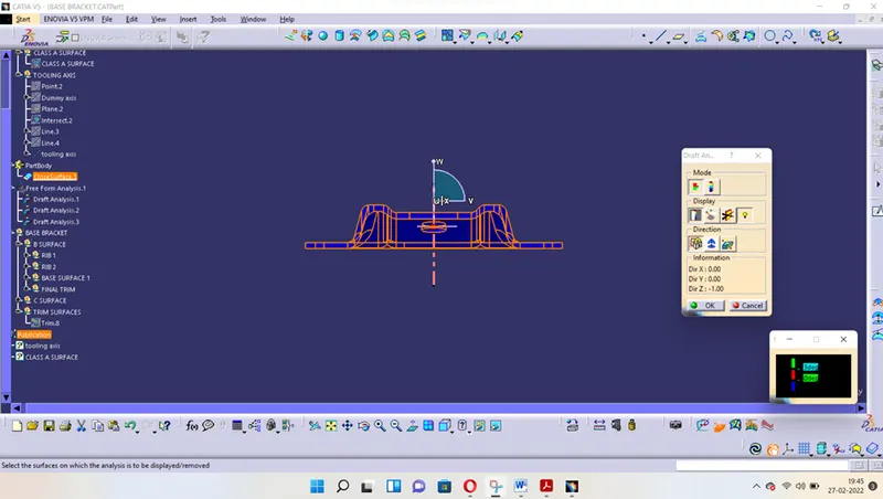
- Open Feature draft analysis option from Insert > Analysis > Feature draft analysis.
- A new window pops up by default it will be in quick analysis mode. Change the range to 2.9deg.
- Next you have to position the compass on the tooling axis by dragging the compass from top right corner of the working area. The W axis of the compass should be inline with the axis.
- Then you have to define the compass by click on compass icon on the draft analysis window. Then lock the positon of the compass by clicking the lock icon.
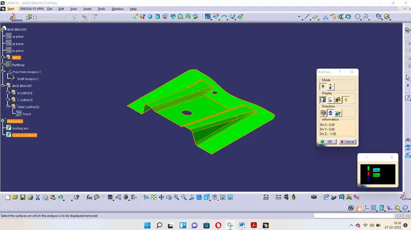
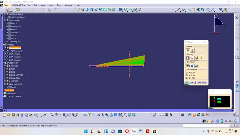
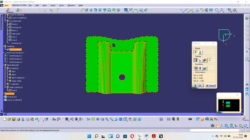
- After that select the surface and the whole surface will shows a color range. For a good draft make the surface fully green.
RESULT FOR DRAFT ANALYSIS:
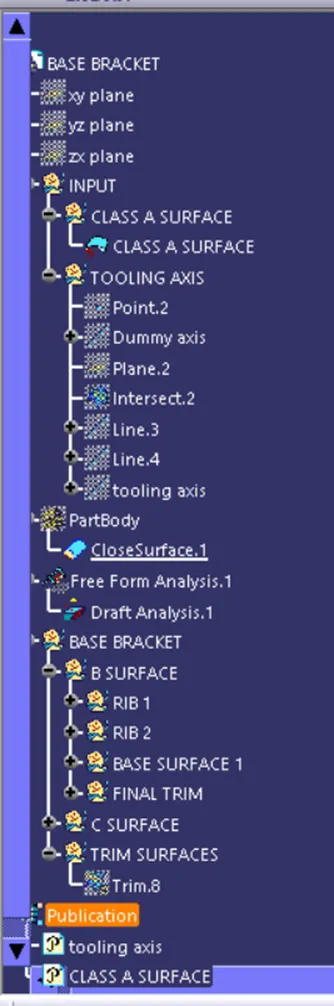
FEATURE TREE:
Front view
Side view
Top view
Isometric view