Advanced Sheet Metal Design Using NX Cad Challenge_2_Box Assembly
Box Assembly Design Using Nx Cad
Objective:-
To design a Box assembly using Siemens NX sheet metal application.
Introduction:-
- SIEMENS NX : NX formerly known as "unigraphics" is an advanced high-end CAD/CAM/CAE, which has been owned since 2007 by Siemens PLM Software.
- SHEET METAL DESIGN:NX sheet metal Design provides the design professional with a complete set of tools to efficiently create and manage sheet metal parts based on the knowledge of material properties and manufacturing processes. NX sheet metal design tools incorporate material and bending information enabling the model to represent both the formed component and flattened blank shapes.
Design Methodology
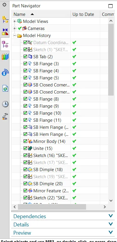
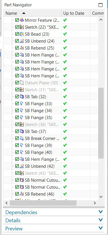
- STEP I : Base was created using Tab command.
- STEP 2 : Walls were created using Flange command.
- STEP 3 : Corners were closed using Close corner feature.
- STEP 4 : Used Flange and Hem flange feature to lock the walls.
- STEP 5 : Whole box was created using Mirror feature command.
- STEP 6 : Unite the two bodies.
- STEP 7 : Create a profile on the side walls.
- STEP 8 : Created a Dimple using the previous profile.
- STEP 9 : Using the mirror feature copied the dimple on the opposite side.
- STEP 10 : Created a emboss on the base using dimple feature.
- STEP 11 : Unbend and Rebend the box.
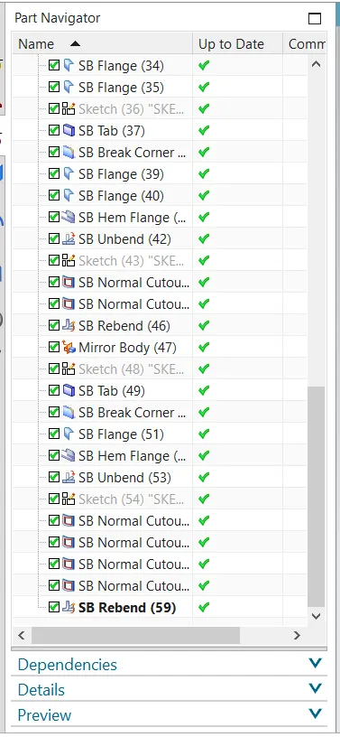
- STEP 12 : Four beads were created on the base using Bead and Mirror feature.
- STEP 13 : Created hem flange on the top of walls on all four sides.
- STEP 14 : Box cover was created using tab command.
- STEP 15 : Flange was created on one side of the box cover.
- STEP 16 : Tab was used to create base for the hinge.
- STEP 17 : Using flange, Hem flange normal cut out hinge was creation the side wall.
- STEP 18 : Using mirror feature another hinge was created.
- STEP 19 : Similarly another hinge was created on the box cover.
- STEP 20 : Changed the colour of the box and cover.
- END
Description:
Box:
STEP 1:
Start NX CAD. Then set the global parameters as per requirements.
Menu-->Preferences-->Sheet metal
STEP 2:
Design a base sketch for box and create a base with Tab option
TAB: A tab is used to form a base of the model along the planar face with respective thicknesses. A sketch with single or multiple closed profiles can be formed as a base
STEP 3:
Use the Flange option to form the side bodies of the box.
FLANGE: The flange feature creates a flat bent profile at an angle to a planar face.
STEP 4:
Then apply a closed corner at the adjacent bends for both sides.
CORNER: The corner feature helps to close a corner where two adjacent bends meet.
STEP 5:
After closing the corner, use Hem Flange to create a ‘U’ profile which self-lock s the sheet metal after bending.
HEM FLANGE: Hem Flange is used to modify the model by folding the edge of the sheet metal flange over onto itself.
STEP 6:
Now mirror the body to form a replicate of the existing body.
MIRROR: Mirror feature mirrors the selected face or body across the selected planes or line.
STEP 7:
Now unite the two bodies (Existing body & Mirrored Body).
UNITE: Unite features used to unite the selected bodies into a single body.
STEP 8:
Now create a sketch and make a dimple on the front & bottom side of the box and mirror it on the backside.
DIMPLE: Dimple is one of the punching processes which is used to raise an area of the model perpendicular to the face where contour sketch is drawn.
STEP 9:
After that, create a sketch for creating beads. Then select the bead option with a circular cross-section and give proper radius and depth and mirror it to make it four beads at the bottom.
BEADS: Beads are used to lift a material along the contour of the sketch.
STEP 10:
Then use hem flange at top edges to create a ‘U’ shaped corners which neglect the sharp edges and create a smooth & safer edge.
HEM FLANGE: Hem Flange is used to modify the model by folding the edge of the sheet metal flange over onto itself.
Lid:
STEP 11:
Create a datum plane at resp distance. Then design a base sketch for the lid and create a base with Tab option.
STEP 12:
Use Flange to create the bends in the lid which seats on the sides of the box.
Hinge:
STEP 13:
Using the right side face of the box as a reference, create a base for the hinge using a Tab option.
STEP 14:
Use break corner option on the hinge base to avoid the sharp edge.
STEP 15:
Then using the flange and hem flange, create a circular profile with the dia where the hinge rod gets inserted to lock.
STEP 16:
After creating flange, unbend the profile with the use of the Unbend option.
UNBEND: This feature is simply used to flatten the bent profile.
STEP 17:
Create a sketch that has to be cut out from the profile with Normal Cutout.
NORMAL CUTOUT: A cutout profile is used to remove the material from the base.
STEP 18:
Then rebend the model & mirror it to get the best view of the model with the replication of the existing body.
REBEND: Rebend is used to restore the model to its bent state.
STEP 19:
Repeat the same steps for mating hinge by taking the top side of the lid as a reference for creating a tab.
Different Views of the model:
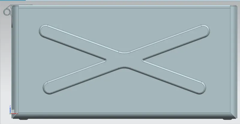
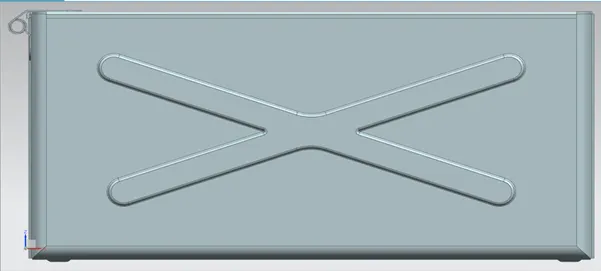
1)Front View:-
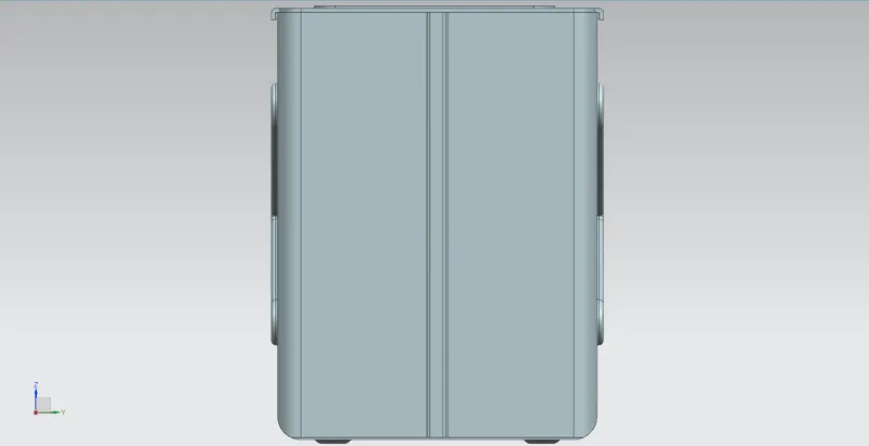
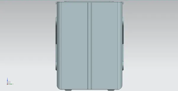
2)Side View:-
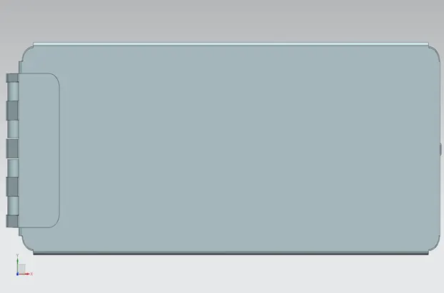
3)Top View:-
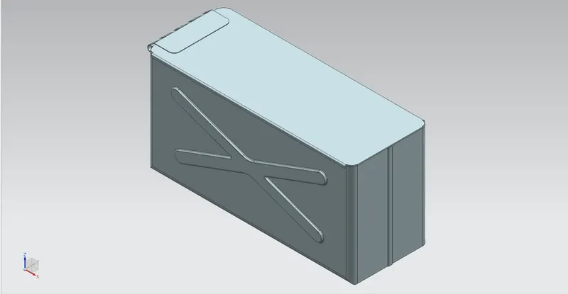
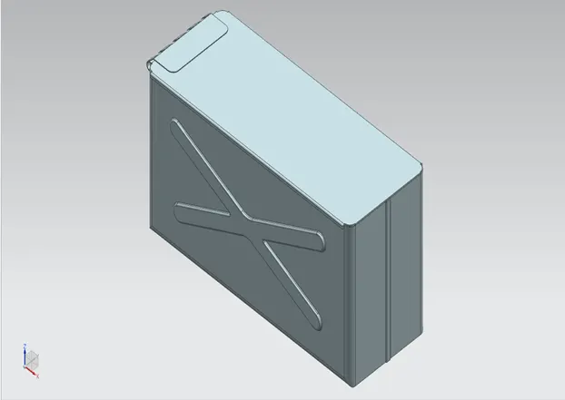
4)Isometric View:-
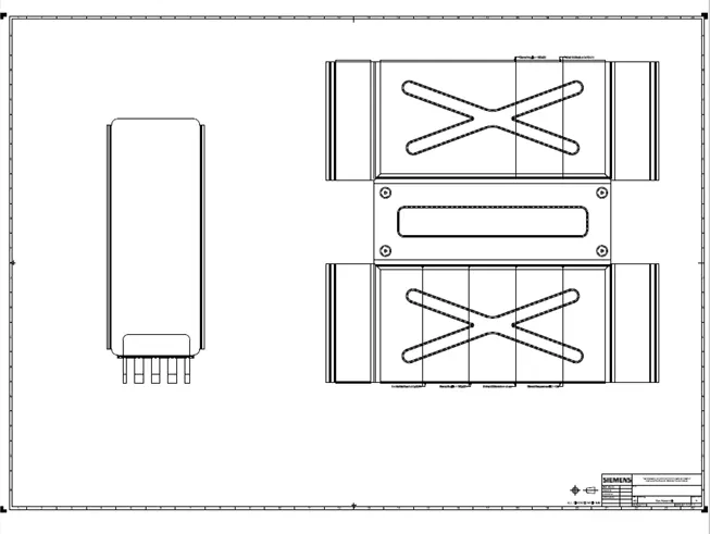
Drawing Sheet:-
CONCLUSION:
Thus the Box Assembly has been designed with the use of NX CAD tool and learned about features involved in creating the sheet metal model.