Door Arm Rest Week 8 Challenge
DESIGN OF DOOR ARM REST
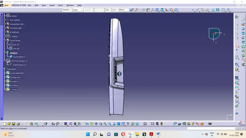
AIM: to design arm rest model from the provided class-A surface.
THEORY:
CLASS-A SURFACE: a surface made by the designer which is given as an input to the plastic modeller to work on. It is aesthetic surface and the outer most surface.
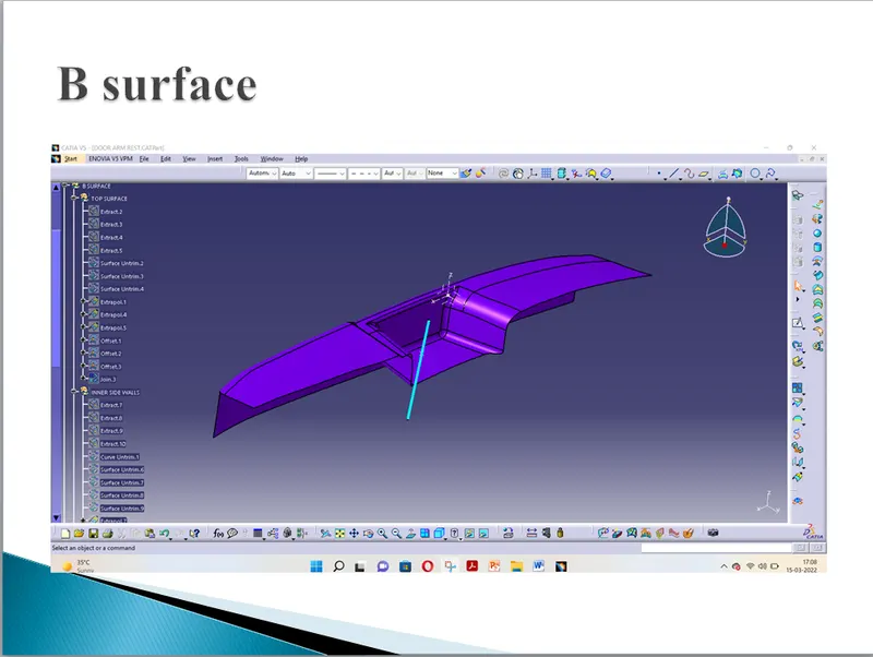
CLASS-B SURFACE: a surface below a certain thickness from the class-A surface is class-B surface. This is the surface that contains engineering aspects of a model.
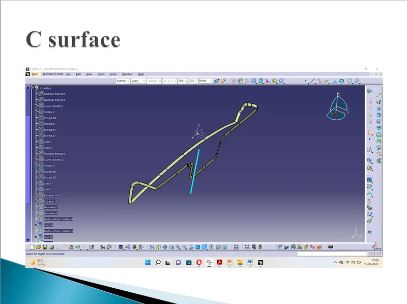
CLASS-C SURFACE: a surface that joins class-A and class-B surfaces is class-C surface.
Following tools were used to make the model:
- Extract
- Un-trim
- Trim
- Extrapolate
- Offset
- Edge fillet
- Boundary
- Sweep
- Join
- Close (part design)
APPROACH:
MAKING TOOLING AXIS AND DRAFT ANALYSIS REPORT:
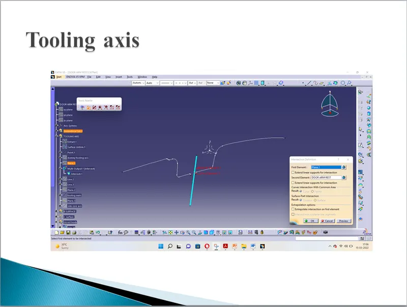
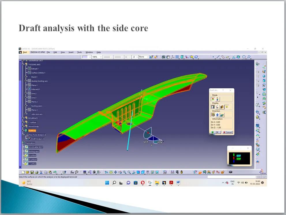
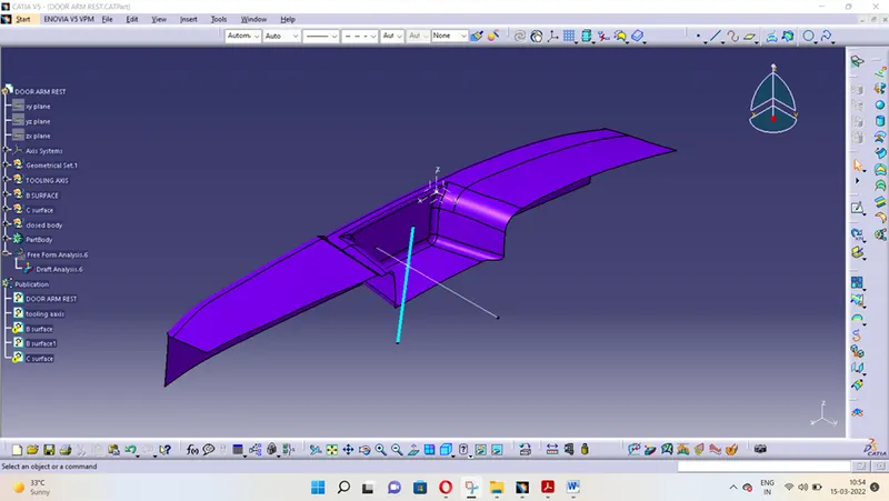
Tooling axis is required because it is the primary requirement in the draft analysis where we can see if our model will be ejected properly or not. This axis is nothing but the direction of ejection of component or the axis of movement of core and cavity. In a simple model, only one tooling axis is enough to clear the model. But as the component becomes complex, we have to give more tooling axis for side core so that every face of the component clears the analysis.
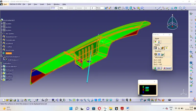
- First make a tooling axis in the z direction.
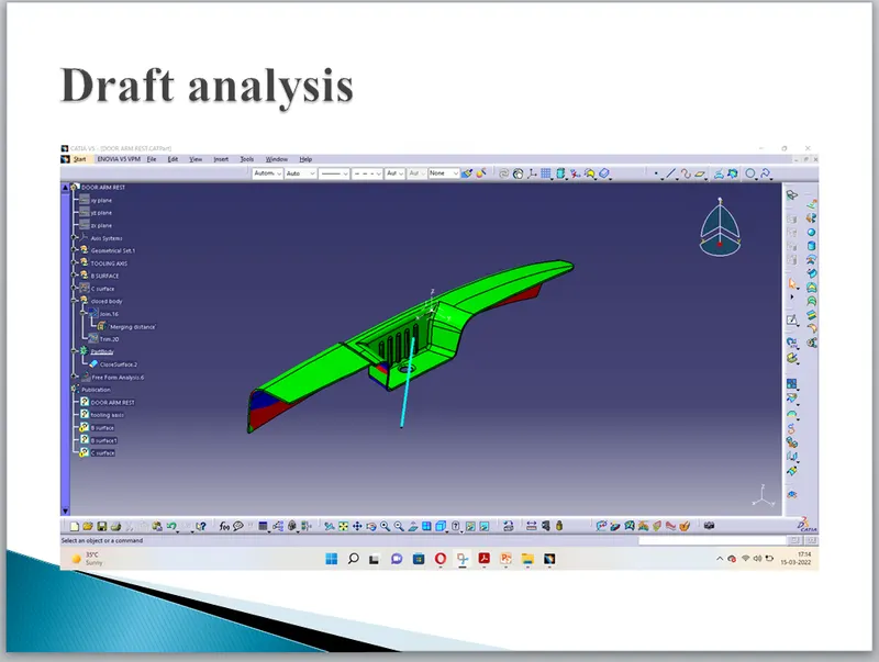
- Go to draft analysis and run analysis on it. As we observed that few of the faces which should have been in green are not in green.
- So we modify the compass which will show the result on the component as it will change its colour.
- Once the required faces are green, we will lock the position of the compass and then change the direction of the tooling axis to that of the compass direction.
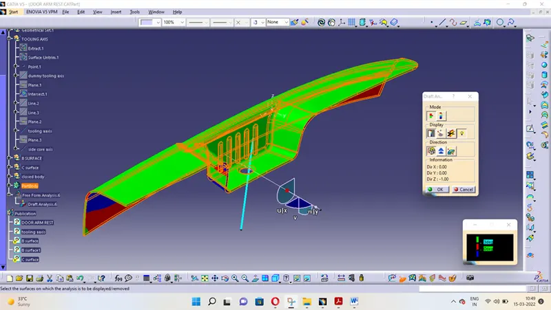
- But still we have not got the entire model in green colour. Few faces of the pocket are not green.
- So we will have to give a new tooling axis which will clear these faces. As shown in the figure.
- We will modify this axis like the previous axis till we get our required results.
CREATING CLASS-B SURFACES:
- The basic approach is to be decided by observing the model. Here we can divide the model in three parts like shown in the pictures. Then only surface remains, is the slant surface which we will deal in a different manner.
- First extract the surfaces marked 2 in the picture and name them first half. Extrapolate them and offset them so that they intersect each other.
- Trim them together and give the fillet according to the fillet on class-A.
- Similarly do it for second half which is marked 1 on the images.
- Now if we see them together we can see a gap between them. This has to be filled by the slant surface but as it is not present we have to approach it in a different manner.
- First create on the intersection point of the fillets and make a slant line there. Make sure it is tangent to the lines representing fillets. This slant line will be our slant surface.
- Extract the boundary of the fillet and smoothen it. Later use this sketch and curve to make a sweep surface.
- There is a small surface on that path on the top side. Extract it and un-trim it. Split it with a line and use the sweep surface and this surface to create a blend between them.
- Later offset that surface. And trim first half, second half and this surface together.
- Now we will do our traditional process of extracting, extrapolating, un-trimming, offsetting and trimming those together to make pocket.
- Once the pocket is complete, we will trim it and the earlier trim together to get class-B surface.
CREATING CLASS-C SURFACES:
- It is complicated to make C surfaces in this model because of the curves and also because of the vertical and horizontal faces present in it. So we break the component and make it one by one and later join it together.
- First make the surface for back surface as it is pretty simple. Extract the boundary and use smooth curve. Sweep it with the surface at 90deg.
- Then start making the vertical surfaces on the top of the component.
- Extract the boundary one by one and use smoothen curve and different surfaces using draft direction.
- For the curved region we will use multi-section solid tool.
- Split the surfaces with the slant lines so that we get a good output. Use the MSS tool and using proper guidelines and proper support, create the surface at the curved portion.
- Repeat the same procedure for every curved portion.
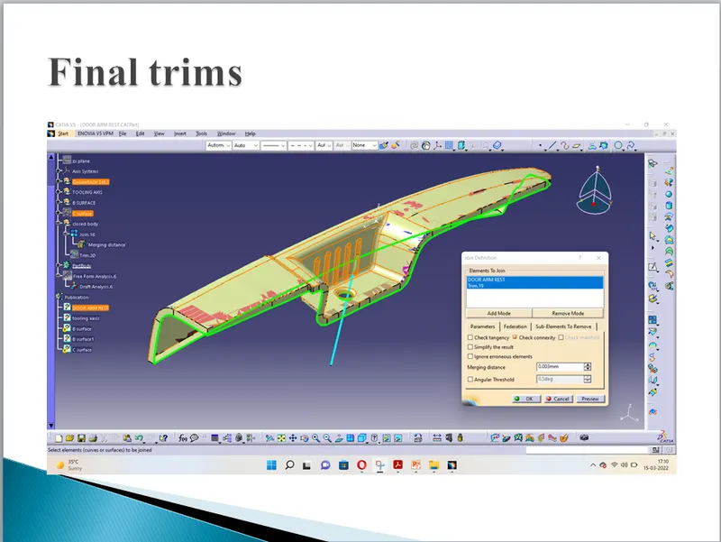
- Later join everything together and to class-A surface.
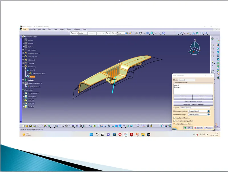
- Trim it with class-B surface to get the surface model.
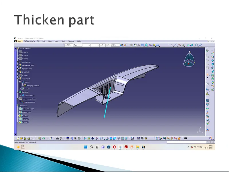
- Close the surface model in the part design workbench.
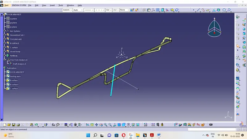
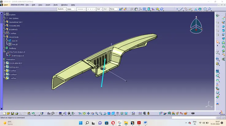
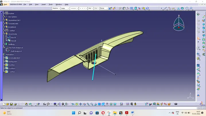
IMAGES OF THE COMPONENT
Isometric view
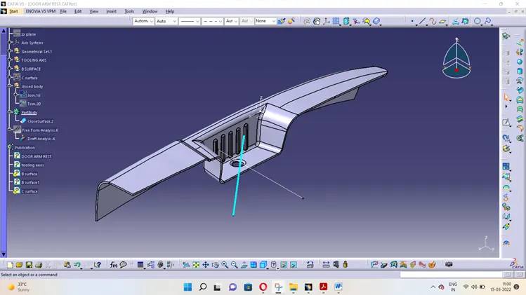
Front view
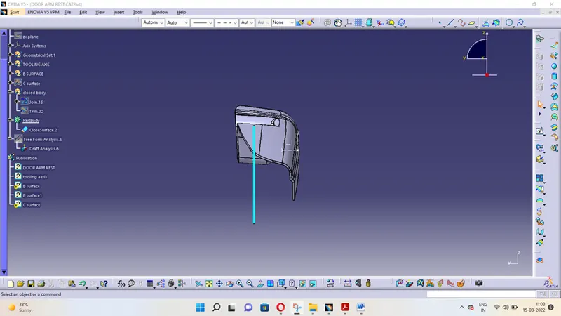
Side view
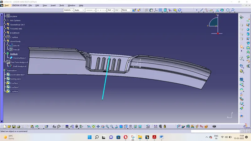
Top view