Week 9 - Attachment Feature Creation - Challenge 2
Attachment Feature Creation - Challenge 2
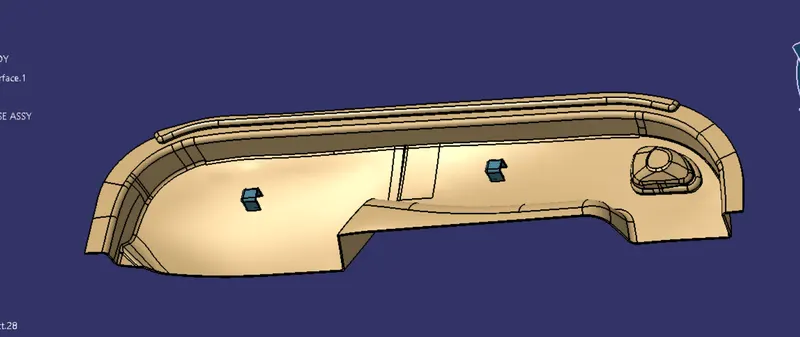
Create the Dog House for the Door Trim considering the design rules mentioned in the video. Consider the thickness of the part to be 2.5 mm.
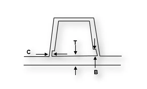
"C" is where the doghouse contacts the backside of the surface
-
Doghouse wall thickness at the intersection of the part wall ( C ) should be 40% or less than the main wall stock ( T ).
-
The height of ( B ) should be between 3.0 – 6.0 mm
AIM:
- To Create the Door Trim Component from the given Class-A surface.
- To Create the tooling axis for the given Class-A Surface meeting the requirements of the draft angle.
- To Create Class B and Class C Surface.
- To Join Class A, Class B, and Class C Surfaces.
- To Attach B-side Features in the component.
- To perform the Draft analysis on the model.
DESCRIPTION:
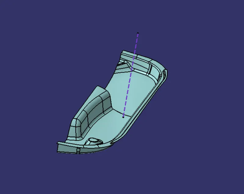
1. CREATING TOOLING AXIS -
- Check for gaps between surfaces for that click on join and then preview.
- If there's any gap between the surfaces join them with a maximum tolerance of 0.003 mm.
DRAFT ANALYSIS
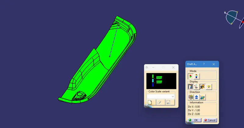
Draft analysis is a method used in design to check whether the component created in CAD is manufacturable based on the draft condition applied. The main reason behind the draft analysis is the part manufactured should be easily removed from the mold. It also gives an idea of the draft angle from the tooling direction. Here we are providing a tooling direction to eject the component easily from the tool. The ideal draft angle given in automotive industries for plastic components is 3 degrees.
Some of the components where draft analysis is done are the hood, fenders, roof, side doors, etc.
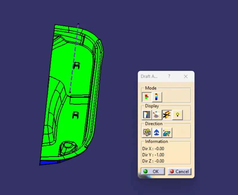
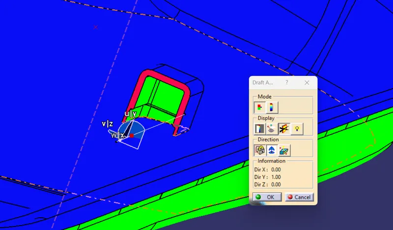
The draft analysis is an essential tool as it helps the user to analyze the draft on various surfaces, the draft analysis in CATIA uses color codes for the identification of the draft. Each color has its meaning for the minimum draft negative draft and under draft.
The draft analysis toolbar provides two modes for analysis of the draft, first is the quick analysis which has three colors for analyzing GREEN, RED, AND BLUE on the other hand other option is the complete analysis mode which enables a few more details into the draft and is used in the complex components like the instrument panel, etc. In the above challenge, we have used the quick analysis made for analyzing the draft here. Now, bring the compass and align it with the tooling axis and click the lock button in the dialog box.
4. CREATING CLASS B SURFACE
- Extract the surfaces from class A using multiple extracts and untrim them.
- Use Extrapolate to make sure that all the untrims are properly intersected to trim and offset the surfaces to 2.5 mm to create the thickness.
- Trim the extra surfaces using the trim command.
- Insert them into the new geometrical set and name them with respective part names.
- Apply fillets to the model after creating the entire surface.
- If the edges are outside the fillet value will be added to the thickness of the component and if the edges are inside, the fillet value will be subtracted from the thickness of the component, for instance, the thickness of the component Is 2.5mm.
- Perform trims one at a time so that it will be clear to understand.
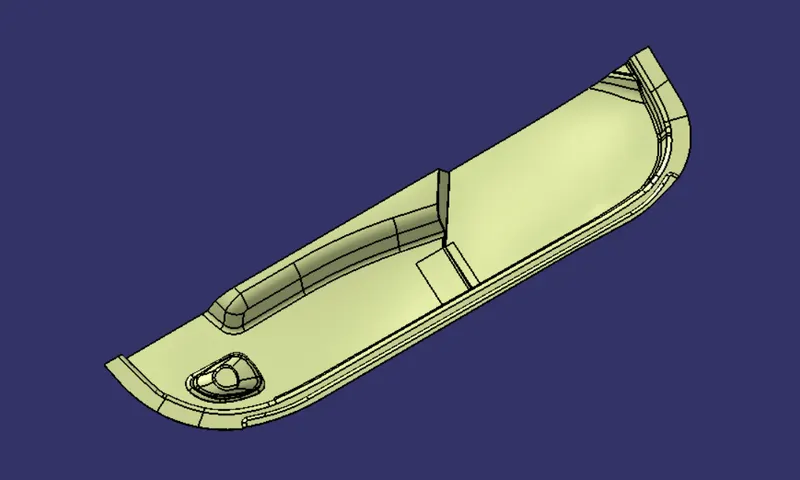
5. CREATING CLASS C SURFACE
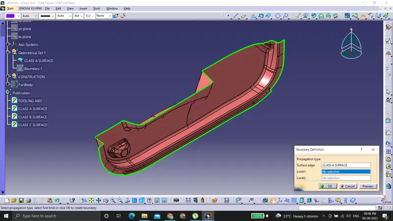
- Extract the boundary from the class A surface using the boundary command.
- Using a disassembly tool to divide the boundary as the boundary contains domains.
- Use sweep command > choose profile type line > subtype as with draft direction > choose guide curve and draft direction > draft angle as 3 degrees> preview.
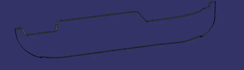
- After getting C Surface then trim the output with the class B surface to get the final output.
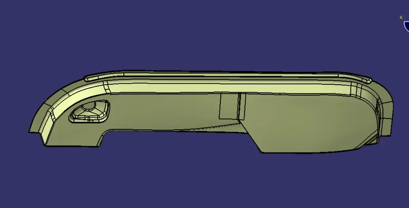
- Join trim with Class A surface
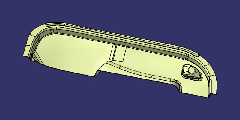
- Now open the part design workbench and use a close body surface to create a solid component.
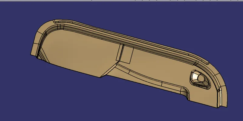
6. B SIDE FEATURES CREATION
DOG HOUSE CREATION
The dog house is an engineering feature used in the plastic trim design. Dog houses are used as a supporting feature. Sometimes other engineering features like snaps; locators, etc. are mounded on them to increase their strength.
The doghouse is created by following the design rules.
The nominal wall thickness guide range is from 0.75 mm to 3 mm for reinforced materials and 0.5 mm to 5 mm for unreinforced materials.
Related Courses
WALL THICKNESS (W) = 0.70 (NOMINAL THICKNESS OF PLASTIC MATERIAL)
This process is usually done by Thicken surface command.
- Sketch Used For DOG HOUSE Creation
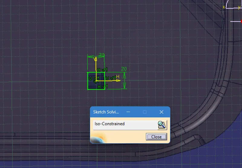
The fillets and the draft are given as per the design rules.
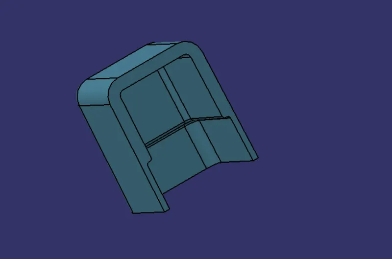
An important thing while designing a doghouse is to maintain 40% less thickness than the wall thickness (T) at the area of the intersection to avoid sink marks. So, a C shape is formed at the intersection.
This can be made using the split command to remove the solid at the intersection.
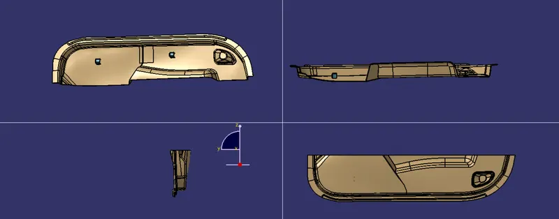
Views:-