Attachment Feature - Ribs on Coin Holder using CATIA V5.
AIM: Create the rib for the Centre console Coin Holder considering the Design Rules.
OBJECTIVES:
- Create a Rib for the Coin Holder following Design Rules for Rib creation.
- Use Positioned sketches and the Sketches should be Iso-Constrained.
- To ensure proper tree structure is followed.
- Geometrical sets should have a proper name based on the sketches present inside of them.
- All the sketches should be created under the geometrical set.
- A detailed report should be done explaining the draft analysis and the tooling axis creation.
- An explanation should be given on the way of creating the tooling axis, particularly the Bisecting method.
THEORY:
- Draft Analysis:
Draft analysis helps to detect if your drafted part is easily removable from the mould (in case of plastic component) or die (in case of sheet metal). All plastic components will have a minimum draft of 0.5 to 3deg. And for automotive sheet metal parts, the draft will be 7deg or more. If a mould wall is perpendicular to the part ejection, there is ample friction or interference between the mould and the part which will not allow one to release from the other. This is why design engineers give a minimum draft to the part.
In CATIA V5 the feature draft analysis dialogue box looks like this:
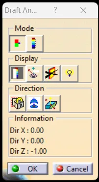
- Mode:
- The mode option let you choose between quick analysis and full analysis mode.
- In quick mode, there are 3 ranges blue, red and green colours. In the case of the plastic component, we will set the draft angle as 3°.
2. Display:
- The first box is to open and close the colour scale dialogue box.
- The second box is the analysis under the running point when activating the checkbOx and moving the pointer over the surface. This option enables you to perform local analysis. Arrows are displayed under the pointer, identifying the normal to the surface at the pointer location (green arrow), the draft direction (red arrow), and the tangent (blue arrow). As you move the pointer over the surface, the display is dynamically updated. Furthermore, circles are displayed indicating the plane is tangent to the surface at this point. The displayed value indicates the angle between the draft direction and the tangent to the surface at the current point.
- Click the No Highlight Representations button to set the display option of highlight effect sources as 'on/off. When checked 'On" the surfaces are selected but they will not be seen in the specification tree.
- Click the Light Effect button and the colours of the analyzed elements react to the light source.
3. Direction:
- The first check box is the locked direction icon which is used to lock the direction of the compass after selecting the specified direction.
- Click on the compass icon to specify the new pulling direction to remove the part.
- Click the Inverse button to automatically reverse the draft direction. When several elements are selected for analysis, the draft direction is inverted for each element when the button is clicked.
- Tooling Direction:
The Tooling Direction is the direction that the mould pulls apart. The mould is built into two separate pieces. You have a Cavity side and you have the Core side. The Core pulls apart from the Cavity and that's the Dyeline or the Tooling Direction. There are different methods to find out the tooling direction. Here we are using bisecting method to find out the tooling direction. We can use any method the ultimate aim is to reduce the cost of manufacturing by reducing the complicity in manufacturing the component.
- Rib Design:
Ribs provide a means to economical stiffness and strength in moulded parts without increasing overall wall thickness.
They also facilitate
- Locating and arresting components of an assembly.
- Providing alignment in mating parts.
- Acting as stops or guides for mechanisms.
This section deals with general guidelines for ribs and part design.
Proper rib design involves five main issues:
- Thickness.
- Height.
- Location.
- Quantity.
- Manufacturability.
Consider these issues carefully when designing ribs.
- Rib Thickness
Thick ribs often cause sink marks and in turn cosmetic problems on the opposite surface of the wall to which they are attached.
The material, rib thickness, surface texture, colour, proximity to a gate, and a variety of processing conditions determine the severity of the sink.
Highly glossy, critical surfaces may require thinner ribs. Placing ribs opposite character marks or steps can hide rib read-through.
Thin-walled parts (<1.5 mm) can often tolerate ribs that are thicker than the percentages in these guidelines. On parts with wall thicknesses that are 1.0 mm or less, the rib thickness should be equal to the wall thickness.
Rib thickness also directly affects mouldability. Very thin ribs can be difficult to fill. Because of flow hesitation, thin ribs near the gate can sometimes be more difficult to fill than those further away.
Flow entering the thin ribs hesitates and freezes while the thicker wall sections fill. Ribs usually project from the main wall in the mould-opening direction and are formed in blind holes in the mould steel. To facilitate part ejection from the mould, ribs generally require at least one-half degree of draft per side. More than 1* of draft per side can lead to excessive rib thickness reduction and filling problems in tall ribs.
Rib Size Generally, taller ribs provide greater support. To avoid mould filling, venting, and ejection problems, standard rules of thumb limit rib height to approximately 5x the rib-base thickness. Because of the required draft for ejection, the tops of tall ribs may become too thin to fill easily.
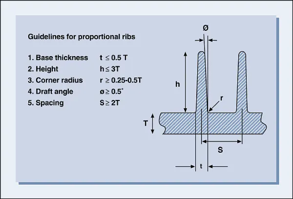
Additionally, very tall ribs are prone to buckling under load. If you encounter one of these conditions, consider designing two or more shorter, thinner ribs to provide the same support with improved mouldability (see figure). Maintain enough space between ribs for adequate mould cooling: for short ribs allow at least two times the wall thickness.
Guidelines for Ribs on Show Surfaces
- Draft.
- Thickness.
- Height.
- Spacing.
- Thickness at Top.
- Optional Radius.
- Design Suggestions.
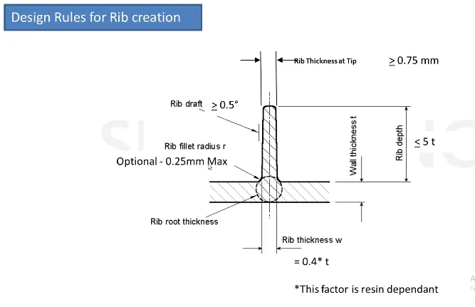
- Rib Draft Angle:
- Determine if the rib is being added to the surface the customer will see.
- Different rule sets for ribs on non-show surfaces versus bosses on show surfaces.
- Draft 0.5 degrees per side minimum.
- It allows the rib to release from the mould.
- Rib Thickness (w):
w=0.4*t
- Measure the base thickness of the rib at the tangent or radius if radii are modelled.
- The larger the area at the base of the rib, the more retained heat.
- The retained heat causes more shrinkage, which causes sinking.
- Rib Thickness at Top:
- Minimum thickness at Rib tip = .75mm
- Rib Fillet Radius (r):
- Optional Rib fillet radius - .25mm maximum.
- Do not want to significantly increase rib thickness.
- Must not violate 40%* thickness requirement.
- Rib Depth:
- Rib Height < 5 x nominal wall thickness.
- Limited by draft and thickness requirements.
- Design Rules for Rib creation:
Design Rules for rib in the Class A surface:
- Draft = 0.5 degrees per side minimum.
- Thickness = Typically 40% wall thickness.
- Height = ≤ 5 x wall thickness.
- Spacing = 3:1 steel height / width ratio maximum.
- Minimum thickness at Tip = .75mm
- Radii = 0.25mm maximum.
- Ribs on the opposite sides of the wall should be offset.
- Ribs should be connected to other structural features where possible.
PROCEDURE:
- Step 1: Determine Tooling Axis and Side Core Axis:
- Extract the base surface of the Coin Holder and place a point in between the Surface > Point definition select surface > Distance = 0mm and place an Axis system on that point.
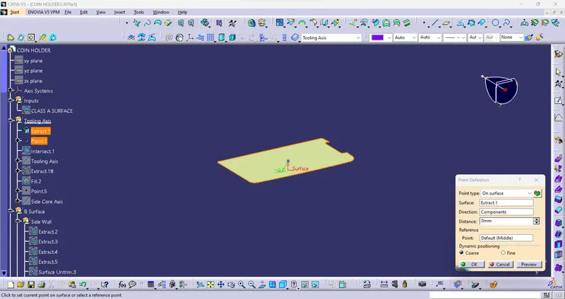
Figure1: Creating a point on the Base Surface.
- With the observation of the Class A Surface, the above which we have created is in the centre of the model and covers major of the parts of the Class A Surface. So we will carry on with the centre point and make a Tooling Axis for the model on the point we have made.
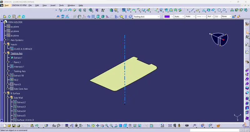
Figure2: The required Tooling Axis for the Coin Holder.
As this model is a little complicated while production we will be requiring a Side Core for this component, hence we will have to make a Side Core Axis.
- The best possible position for the Side Core Axis will be along with the hole in Class A Surface, so let's take the boundary of the hole.
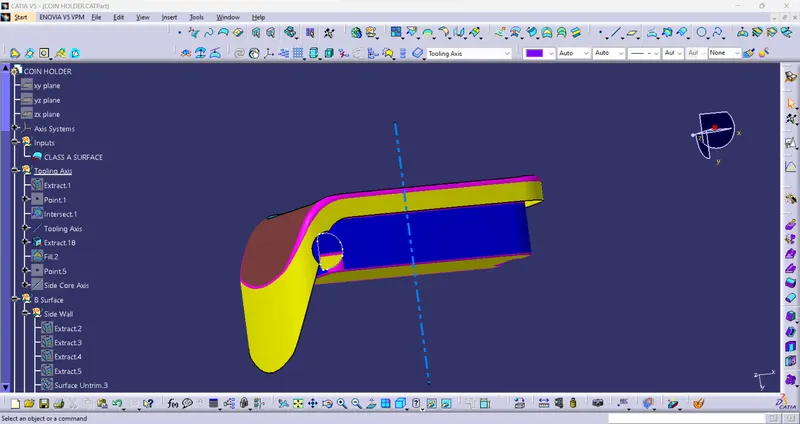
Figure3: Taking the boundary of the hole section in the Coin Holder.
- Now we will fill the boundary of the hole and create a Surface, on the centre of the Surface we will create a point.
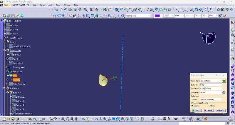
Figure4: Taking the boundary of the hole section in the Coin Holder.
- From this point, we have Created the Surface of the hole part let's make a line which will be our Side Core Axis.
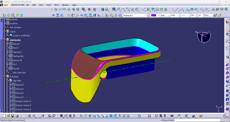
Figure5: The required Side Core Axis for the Coin Holder.
- Now that we have the Tooling Axis and the Side Core Axis, let's publish the Tooling Axis, Side Core Axis and the Class A Surface of the Coin Holder.
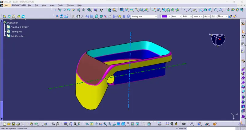
Figure6: Publication of the Tooling Axis, Side Core Axis and the Coin Holder.
Step 2: Creating Ribs for the Coin Holder:
Now we need to create the Ribs on the Base of the Coin Holder Body.
- Let's start by creating a point on the Tooling Axis and Extracting the base of the Coin Holder Body.
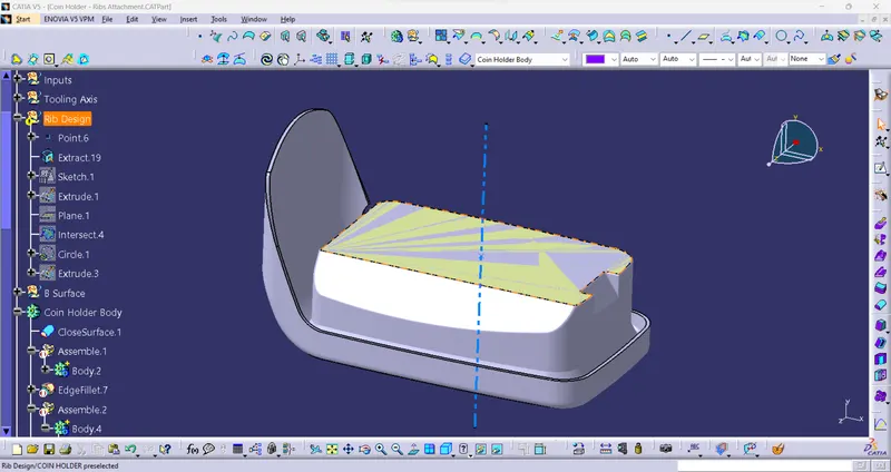
Figure7: Point made on Tooling Axis and Extracted Base.
- Now let's make the sketch required for the creation of the Ribs.
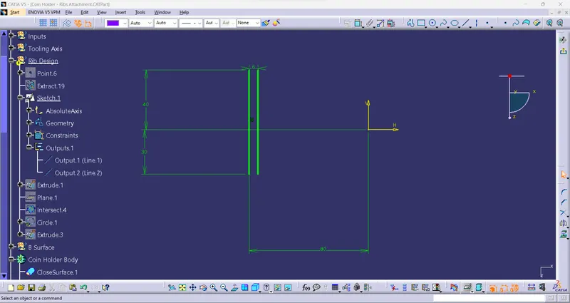
Figure8: Sketch for the creation of Ribs.
- Once we have created the required sketch for the ribs now let's Extrude them so that we can create a solid out of them.
- We will Extrude the sketch to a height of 12.5 mm
- Calculation: 5 x Thickness of the Component which is (5 x 2.5 = 12.5)
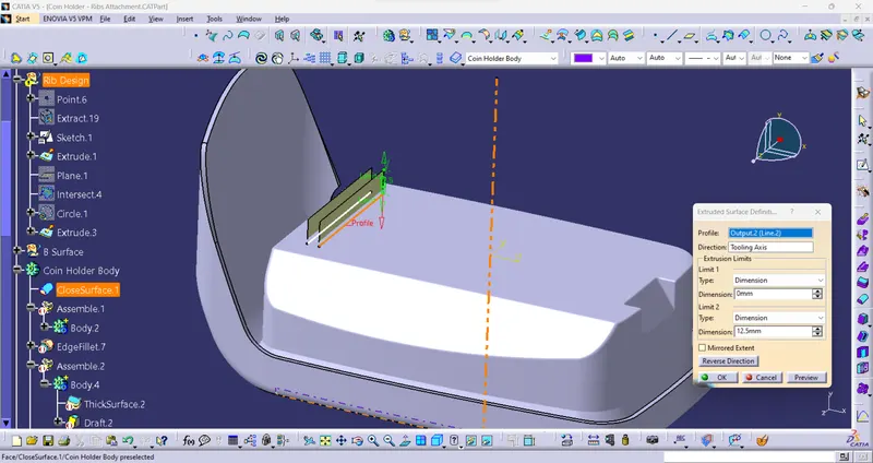
Figure9: Extruding the sketch of Ribs with the calculated values.
- Now let's use the Thick Surface feature from the part design to make a solid body out of the Extrude.
- We will give the thickness of the Ribs as 1mm.
- Calculation: 0.4 x Thickness of the Component which is (0.4 x 2.5 = 1)
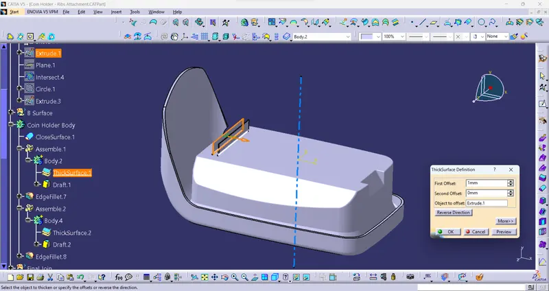
Figure10: Giving Thickness to the Extrude of Ribs with the calculated values.
- Now that we have created the Solid Body of the Ribs we need to give the Draft to it.
- We need to give 0.5 deg draft to 4 sides of the rib.
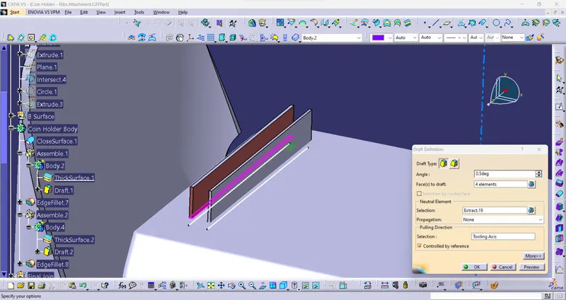
Figure11: Giving Draft to the Solid Body.
- Assemble the Rib Part Body inside the Coin Holder Body and then give Edge Fillet to all faces of the Rib for 0.25mm.
- Note while Creating more than one Rib these steps must be followed:
- Ribs Height/Width (mm)= 3:1
- 12.5/Width = 3
- Width = 12.5/3
- Width = 4.1; (Width should be > 3)
- Here we have taken 5mm width while creating the second rib.
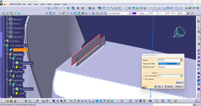
Figure12: Assembling the Rib Body to the Coin Holder Body and giving the required Fillets.
- Now let's create a Plane on the Tooling Axis and see this plane in creating an Intersection between the reference Plane in XY Direction and Coin Holder Body
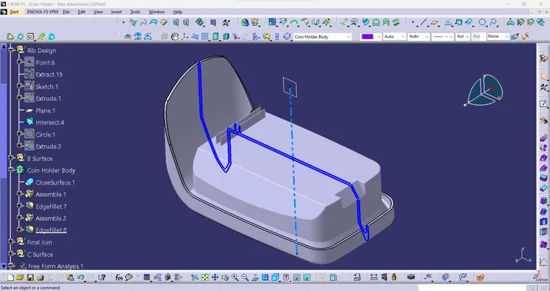
Figure13: Intersection between the Plane and the Coin Holder Body.
- Using the above Intersection let's make some measurements to check that our design is safe according to the Design Rules.
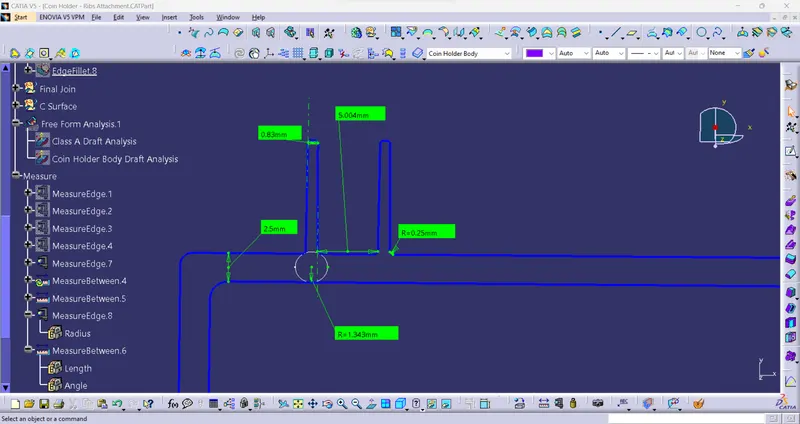
Figure14: Measurements made to cross-check with the Design Rules.
- Step 3: Draft Analysis of the Coin Holder with Ribs :
- Change View Mode Customization to the Material mode for the Draft Analysis.
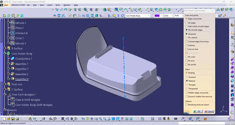
Figure15: Material Mode.
- Go to INSERT > ANALYSIS > FEATURE DRAFT ANALYSIS and move the compass to the Tooling Axis. Change the range to 3°. Apply the settings as shown in Figure 26.
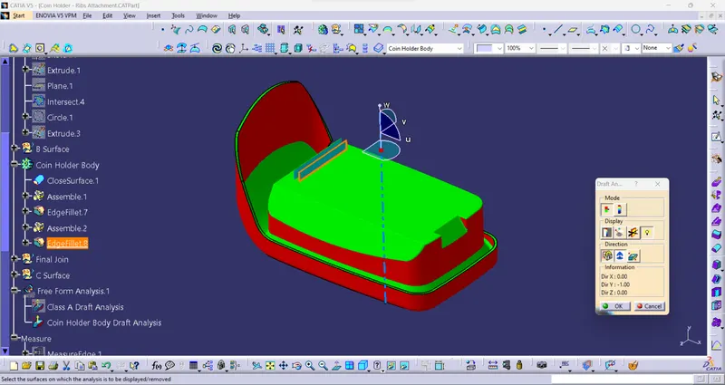
Figure16: Draft Analysis tools Coin Holder Body.
- The Draft Analysis of the Coin Holder is shown below the Component is safe.
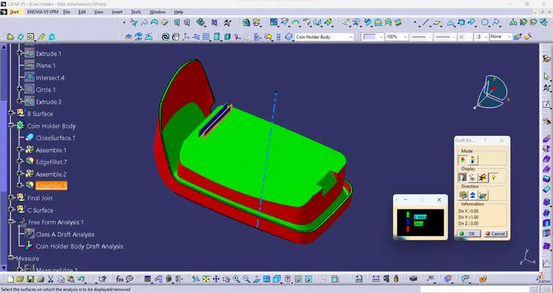
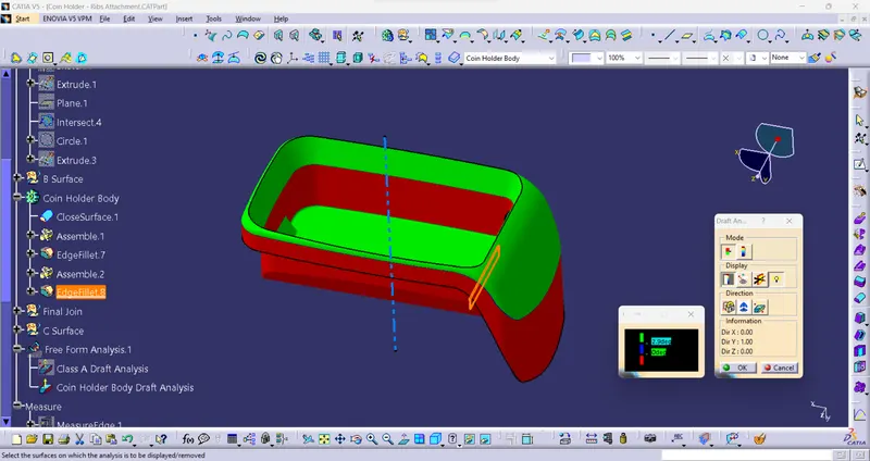
Figure17: Screenshot of Draft Analysis of the Coin Holder Body with Ribs.
- Terms asked to Mention:
- Tree Structure:
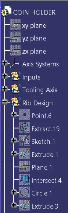
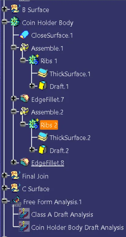
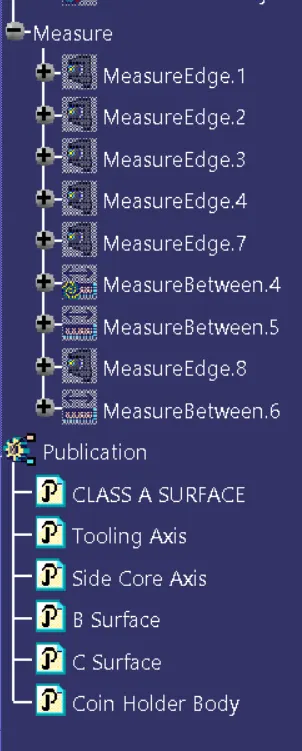
Figure18: Screenshots of Tree Structure of Coin Holder.
- Screenshots of the model with the proper colour code of the draft angle in various orientations (Isometric, Front, Side, and Top View):
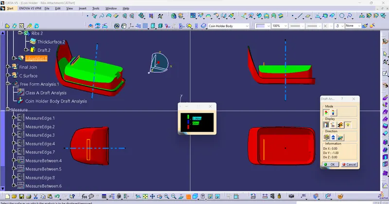
Figure19: Model in Various Views.
RESULT:
- Creation of Tooling Axis and Side Core Axis for the Coin Holder.
Figure20: Result of creating Tooling Axis and Side Core Axis of Coin Holder.
- The Creation of the Ribs for the Coin Holder using the below Calculations.
- Draft = 0.5 degrees per side minimum. | We need to give 0.5 deg draft to 4 sides of the rib.
- Thickness = Typically 40% wall thickness. | Calculation: 0.4 x Thickness of the Component which is (0.4 x 2.5 = 1)
- Height = ≤ 5 x wall thickness. | Calculation: 5 x Thickness of the Component which is (5 x 2.5 = 12.5)
- Spacing = 3:1 steel height / width ratio maximum.
- Minimum thickness at Tip = .75mm
- Radii = 0.25mm maximum. | Edge Fillet to all faces of the Rib for 0.25mm.
- Ribs on the opposite sides of the wall should be offset.
- Ribs should be connected to other structural features where possible.
- Note while Creating more than one Rib these steps must be followed:
- Ribs Height/Width (mm)= 3:1
- 12.5/Width = 3
- Width = 12.5/3
- Width = 4.1; (Width should be > 3)
- Here we have taken 5mm width while creating the second rib.
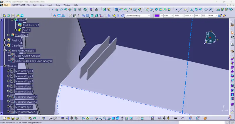
Figure21: Results of the Ribs made for Coin Holder.
- Using the Intersection let's make some measurements to check that our design is safe according to the Design Rules.
Figure22: Result of Design Rules checking.
- The Coin Holder Body with Ribs has passed the Draft analysis test as the draft values of the Coin Holder are less than 3° and the Holder is safe for production.
Figure23: Result of Draft Analysis of Coin Holder Body with Ribs.
CONCLUSION:
Creation of Rib on Coin Holder has been successfully done by following all the Design Rules and the Tooling Axis has been created following OEM Standards.