Week 9 - Attachment Feature Creation - Challenge 1
ATTACHMENT FEATURE CREATION (RIBS) FOR A CENTRE CONSOLE COIN HOLDER USING CATIA v5
Objective
To design ribs for a previously designed model of a centre console coin holder according to proper guidelines required for plastic moulding
INTRODUCTION
Manufacturing process: Injection Molding
Brief about the process
It is a manufacturing process used for the mass production of plastic components. It works by injecting molten material (plastic) into a mold. Under the application of heat and pressure, the material solidifies into the required shape. Once the product cools, it is ejected from the mold with the help of ejector pins.
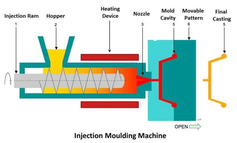
Terms in the injection molding process associated with this project
Draft
To facilitate easy removal of components from the mold, it is necessary to add a taper all along the surface with reference to the tooling direction. This taper is termed as a draft and its value ranges from 0.5 degrees to 3 degrees, with the latter being the most widely accepted norm.
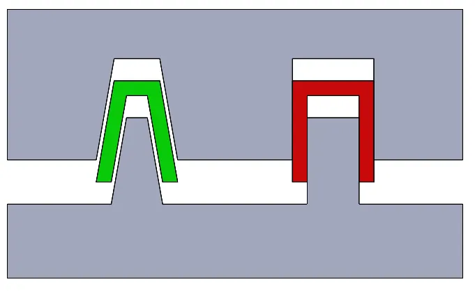
The Draft analysis command in CATIA enables to detect if the drafted part can be removed in an easy manner. This analysis is performed based on colour ranges identifying zones on the analyzed element where the deviation from the draft direction at any point, corresponds to specified values.
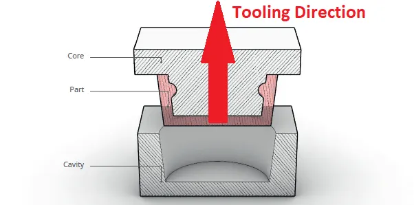
Tooling direction
The direction along which the core pulls apart from the cavity is termed as the Dyeline or the Tooling direction.
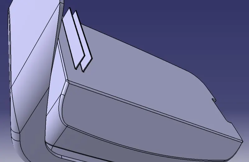
Ribs
Ribs are a feature used in injection moulded plastic parts to provide extra support and strength to the part. They are thin extrusions that run perpendicular from a wall or a plane.
Software : CATIA V5
CATIA (an acronym of Computer Aided Three-dimensional Interactive Application) is a multi platform software suite for CAD, CAM, CAE, PLM and 3D , developed by the French company Dassault Systèmes.
The version of CATIA used for this project is V5. For the target model, the features in the part and surface workbench were extensively used.
Target Model: Coin holder used in automobiles
A coin holder is a plastic component usually found in automobile interiors especially as a part of the door arm rest.
Methodology in CATIA associated with this project
Bisecting line method
Since draft is measured with reference to a tooling axis, the first step after importing the model into CATIA was the creation of a tooling axis. To incorporate for tool clearances due to the presence of tapered surfaces in the part, the bisecting line method was used to create the tooling axis.
After converting the surface into a 2D profile using the Intersection command from the surface workbench, two inclined lines were created using the endpoints of the 2D curves which represented the tapered faces. Using a bisecting line type, a third line was created along the centre point which signified the coincidence of the tapered faces. This line was the required tooling axis for this component.
NOTE: This project did not have features which needed a titled tooling axis and hence the tooling axis was created using a bottom face extract and creating a line through the centre point.
Draft Analysis
The draft analysis command in CATIA helps to detect whether the drafts provided in the model will facilitate easy removal of the component during manufacture.
This analysis is performed based on colour ranges identifying zones on the analyzed element where the deviation from the draft at any point, corresponds to specified values.
- When the draft angle value of the surface is equal or smaller than a graduated value, the color below the graduated value is applied
- When the draft angle value of the surface is greater than the greatest graduated value, the color above this graduated value is applied
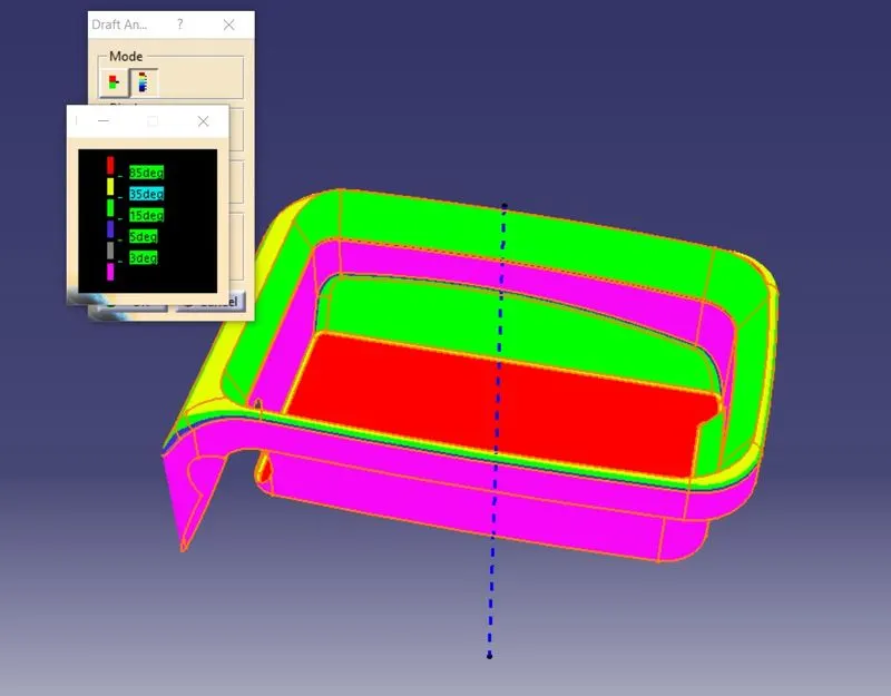
In this project, the required draft for all surfaces were chosen as 3 degrees and hence the quick mode option in draft analysis was chosen which incorporated two different colours for two input values.
DETAILED PROCEDURE
- Create sketches for the rib design
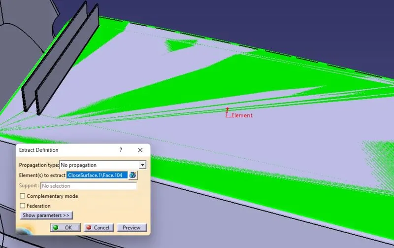
1. Extract the bottom surface to create a positioned sketch for the rib
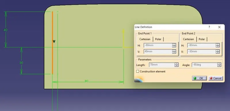
2. Create a positioned sketch for the first rib
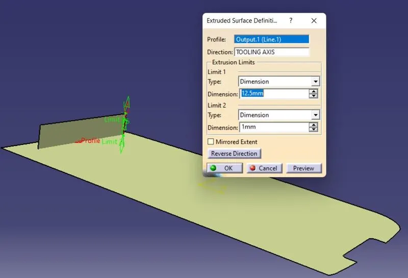
- Extrude the sketches along the tooling direction
1. Determine the height of the extrusion from the proper calculations listed in the DFM guidelines for a rib design in a plastic component: Height of the rib=5* wall thickness
2. In this case, the wall thickness= 2.5mm; Hence the hight of the rib= 5*2.5=12.5mm
3. Add an additional 1mm depth for the extrusion in the opposite direction as well to ensure no gap between the rib and the coin holder
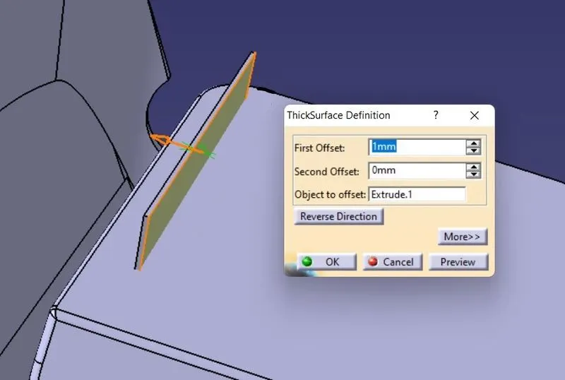
- Thicken the extruded surfaces with an appropriate thickness value to create a solid feature
1. Using the thick surface tool from the part workbench, the extruded surface can be converted into a solid body and later this body can be added to the parent body using the assemble tool
2. The thickness of the rib is determined by the formula: Rib thickness=0.4*wall thickness; in this case, 0.4*0.25mm=1mm
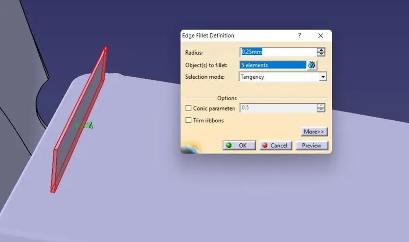
- Add edge fillets according to proper guidelines to refine the design
1. Edge fillets are added to the sharp corners of the rib
2. According to DFM guidelines, the optimal value for rib thickness is 0.25mm
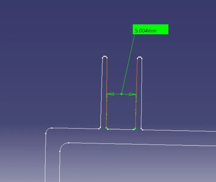
- Create a second rib
1. Create a second rib at an appropriate distance away from the first by repeating the previous steps
2. The optimal distance between ribs, according to DFM guidelines is (2*thickness of wall) which in this case equals to a value equal to or above 2*2.5mm= 5mm
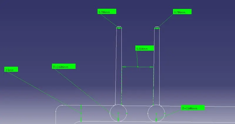
- Ensure proper measurements for the ribs according the DFM guidelines
1. Rib tip thickness=0.75mm (approx.)
2. Rib root thickness= wall thickness (=2.5mm) (Measured by creating a circle using the tritangent option)
3. Distance between ribs= 5mm or above
- Perform draft analysis
1. Perform draft analysis to ensure that the part is manfacturable
2. Observe the results and make modifications if needed
DRAFT ANALYSIS: RESULTS
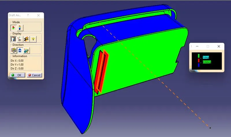
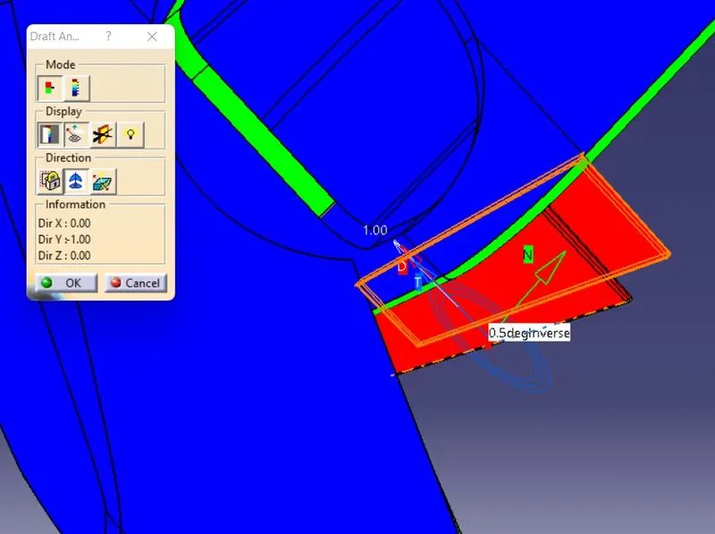
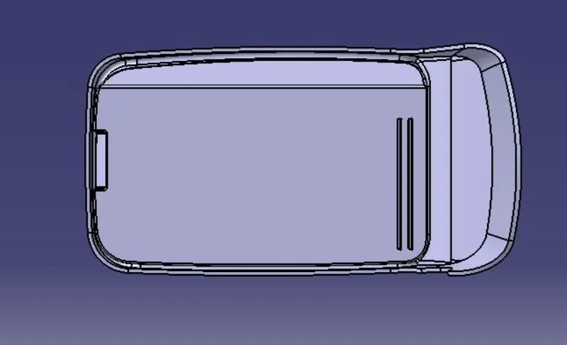
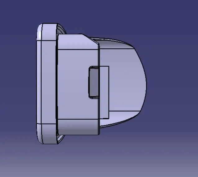
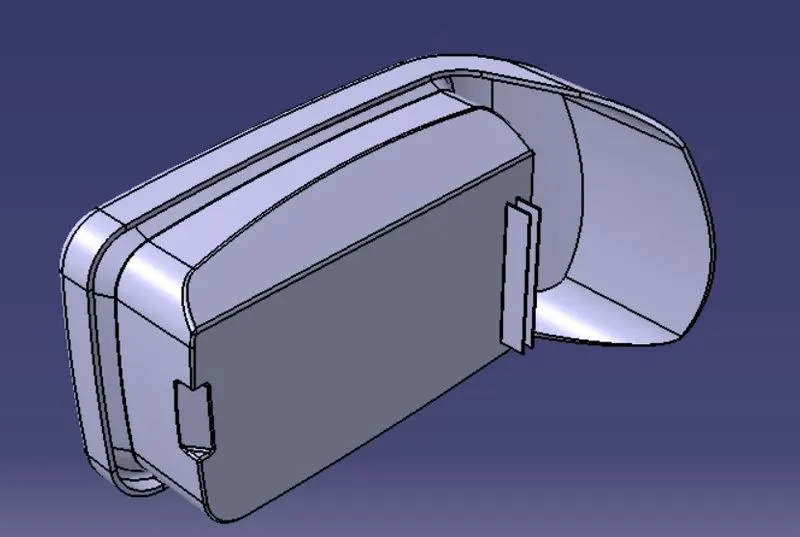
STANDARD VIEWS OF THE SOLID MODEL
TOP VIEW
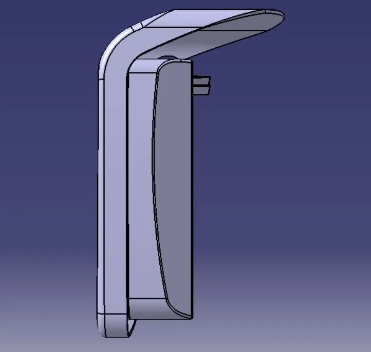
SIDE VIEW
FRONT VIEW
ISOMETRIC VIEW
CONCLUSION
This project imparted a great deal of knowledge regarding the creation of ribs in a plastic component by following proper DFM guidelines. It also clarified the need for attachment features in a plastic component and how it helps the designing process from an economical point of view.