MODELING AND ASSEMBLY OF AN AMERICAN CHOPPER USING SOLIDWORKS
MODELING AND ASSEMBLY OF AN AMERICAN CHOPPER USING SOLIDWORKS
OBJECTIVE
To have a comprehensive understanding of sketching, part modelling and assembly in Solidworks by designing the model for an American Chopper and make it presentable using proper rendering tools and reports.
INTRODUCTION
Software-SolidWorks
Originally developed by an MIT graduate Jon Hirschtick in 1993 and later acquired by a French software corporation, Dassault Systemes SE (abbreviated 3DS), in 1997, Solid Works is a solid modeling computer -aided design (CAD) and computer -aided engineering (CAE) computer program.
It utilizes a parametric feature -based approach. This means that the model can be accessed from any angle since it is dimensioned in a completely 3-D environment. This, in turn, ensures two important principles in designing- repeatability and changeability.
The 2019 version of Solid Works has been used in this project.
Target Model-American Chopper
The name stands originally for the American television show which focussed on the construction of chopper styled motorcycles. A typical chopper bike is characterized by its long fork and radically modified steering angles. The American chopper bikes, known as Orange County Chopper Bikes, are manufactured by Orange County Choppers based on New York and caters according to customer specifications and themes.
The model used for this project has a typical chopper design,single seater, with larger rear wheels, twin cylinder engine, twin exhausts and a long fork. Appropriate materials, decals and lighting has been given towards the end of this project to make the model presentable and realistic.
PROJECT OVERVIEW
Project Outline
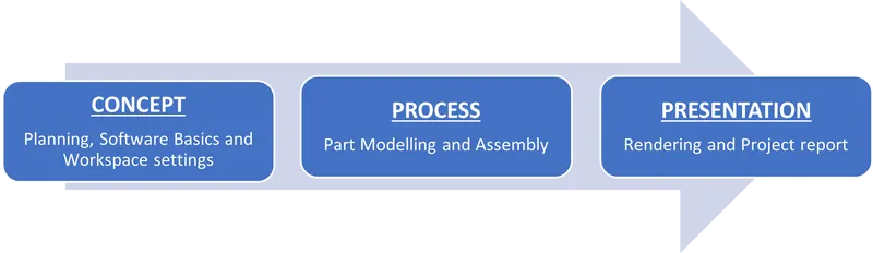
DESIGN OVERVIEW
Design Flowchart

Features and Tools
Sketch
To create basic sketches, the standard options such as line, arc, circle, spline etc were used. Offset, convert, intersection and trim entities options were extensively used to create sketches from existing edges or sketches. The Sketch Block tool was used in the modeling of the chain links. The Sketch Picture option was used to import the 2-D sketch of the chopper to be used as a reference.
Curve
The important tools used in the section includes Projected curve, Split line and Composite curve.
Reference Geometry
Reference Planes were created to aid the modeling process and Reference Axis was used to relate to an existing axis when creating a sketch or revolved geometry.
Solid
The following are the important solid modeling features used in this project:
- Boss/Base: Extrude, Revolve, Sweep, Loft
- Cut: Extrude, Revolve, Sweep
- Pattern/Mirror: Linear, Circular, Curve Driven, Mirror
- Other: Fillet/Round, Chamfer, Shell, Combine, Split, Move/Copy body, Delete/Copy body, Dome
Surface
The following are the important surface modeling tools used in this project:
- Sweep
- Trim
- Boundary Service
- Knit
- Extrude
Design Process
Units
The MMGS unit system has been used in this project.
Workspace setup
For the sake of convenience, a separate template was created with the desired units for modeling. According to purpose and ease of understanding during the assembly phase, the basic planes (Front, Top and Side) were renamed while modeling each part.
A 2-d sketch of the chopper was used, during the design stage of the chassis, for the sake of a proper reference.
A new feature when used for the first time in the modeling process, has been explained in detail, in this report, under the design process explanation of the part in which it was used. Repetitive explanations of the same feature have been avoided.
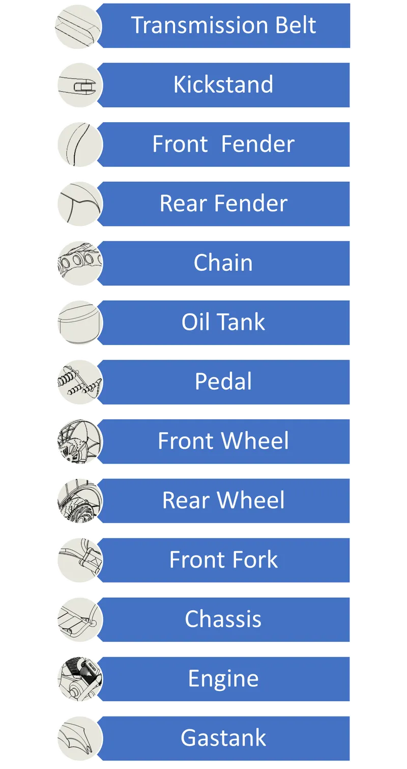
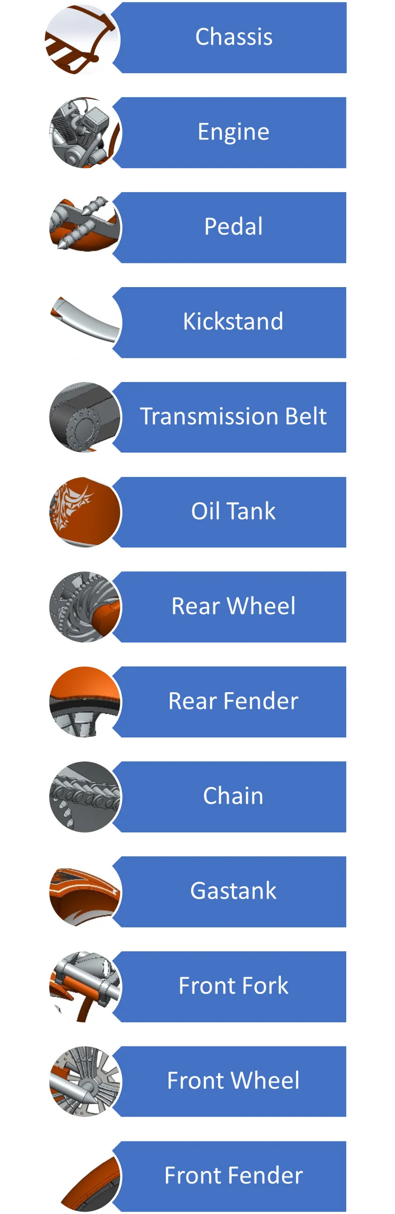
PART MODELING
Transmission Belt
A loop of flexible material, used between parallel shafts in a vehicle, these are used commonly to transmit power or to track relative motion between rotating parts.
The belt was designed using a combination of two sketches with on being drawn using basic line and arc commands and the other being offset from the first. The loop was then extruded into a solid body using the Boss/Base Extrude feature by specifying the appropriate dimension. Owing to sharp edges resulting from extrusions, the Fillet/Round feature was used to smoothen these edges.
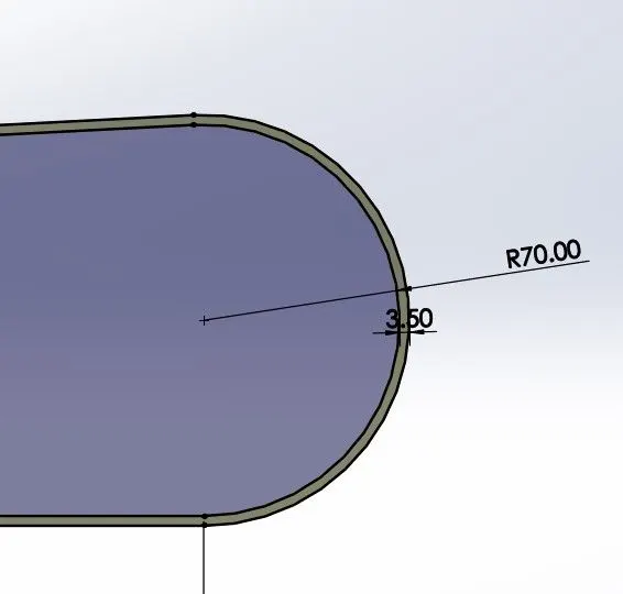
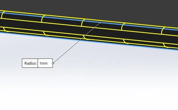
Fig1: Offset Fig2: Fillet feature
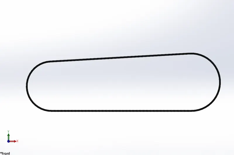
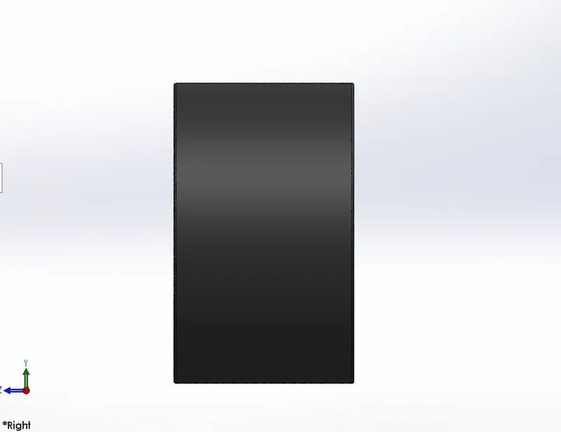
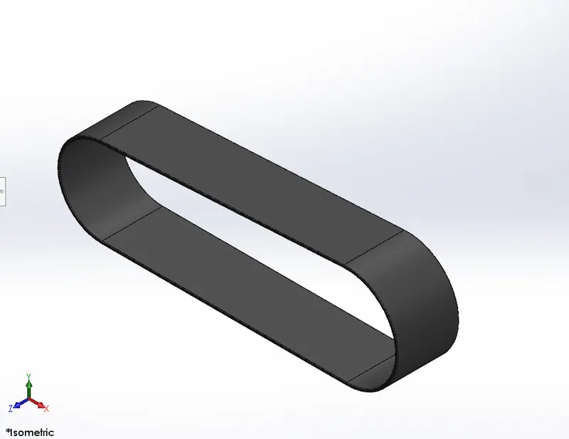
Fig3: Front View Fig4: Side View Fig5: Isometric View
A Matte Rubber appearance was chosen for this part to make it realistic during the rendering.
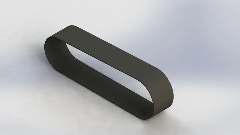
Fig6: Final Render
Kickstand
A kickstand, as the name suggests, is a device which helps to keep the bike upright without the aid of a person. This model has a side stand which is mounted to the bottom left corner of the chassis.
The curved profile of the kickstand was first drawn in a standard plane, using the Spline tool under the sketch menu. Solid Works surfaces are based on a mathematical formulation called NURBS (Non-Uniform Rational B-Spline). It uses weighted points to define a curve. A spline provides greater control over a curve since it provides control handles, which can be properly dimensioned using a combination of magnitude (weight) and direction (angle).
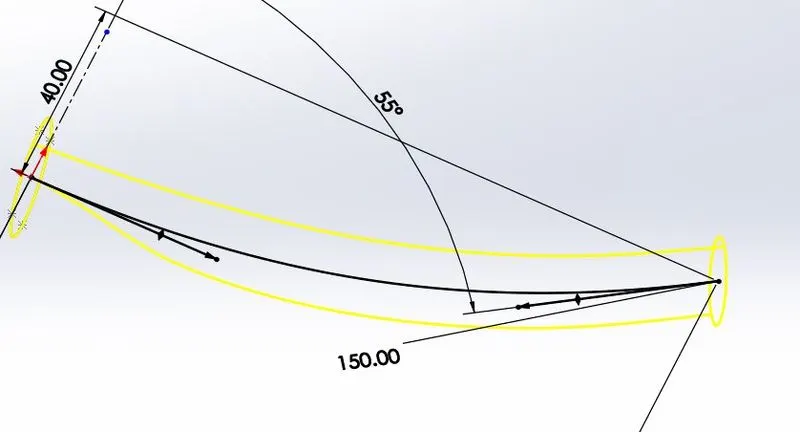
Fig7: Spline
The purpose of the spline was to act as a guide curve between two elliptical profiles drawn at both ends of it. The right end point of the spline was used to create a Reference Plane to draw an ellipse.
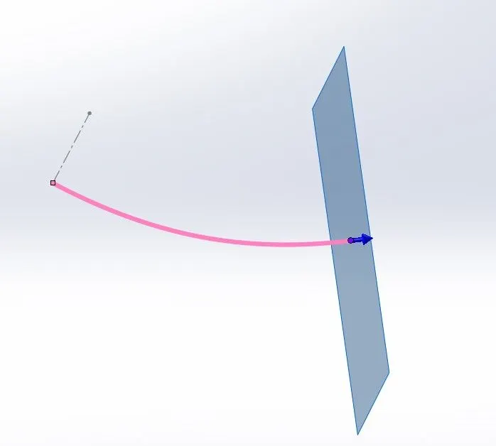
Fig8: Reference Plane
The solid body was then created using the Lofted Boss/Base feature (adds material between two or more profiles to create a solid feature) which used the spline as a guide curve and the elliptical profile as the shape.
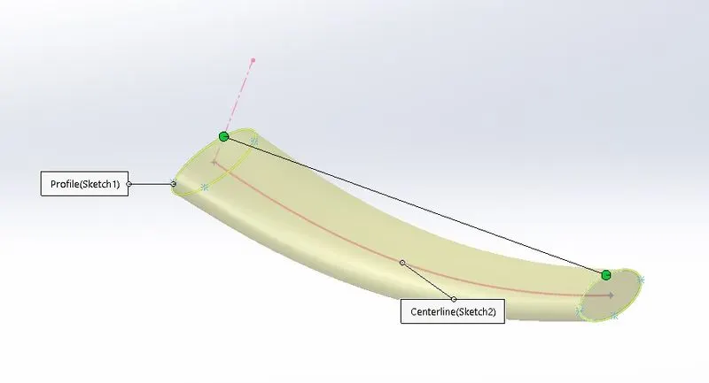
Fig9: Lofted Boss/Base
The ends of the solid body were then capped off using the Dome feature (adds a dome to the planar or non-planar faces of a model).
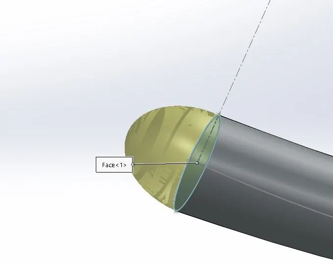
Fig10: Dome
The left dome was then slotted used the Cut Extrude feature (Cuts a solid body by projecting a sketch) to provide the recess for clamping the kickstand on to the chassis.
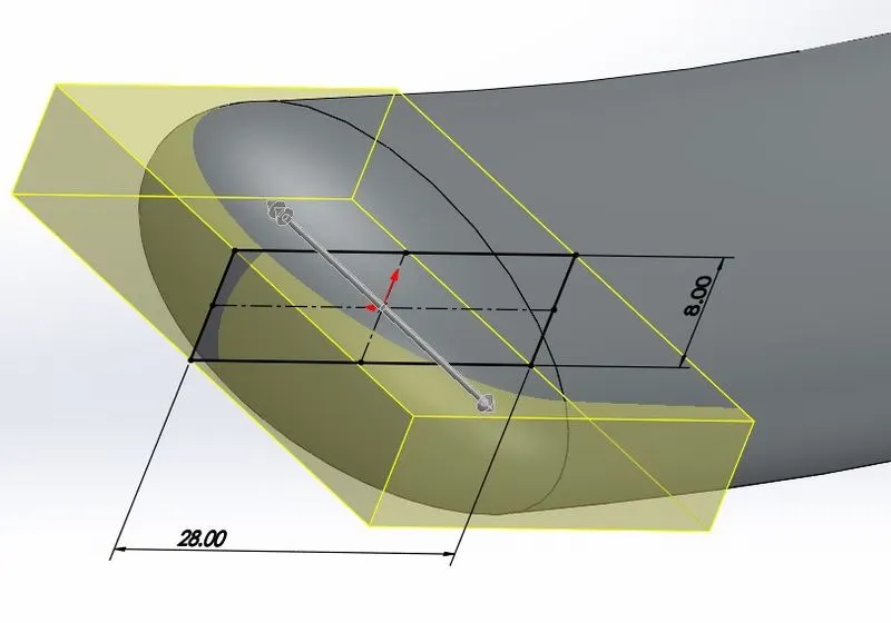
Fig11: Cut Extrude
The right end of the kickstand was split using a line to provide for the flat surface which is a characteristic of kickstand design. For this the Split feature (to create multiple bodies from a single body) was used.
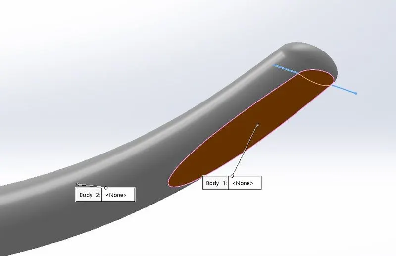
Fig12: Split
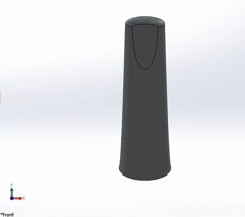
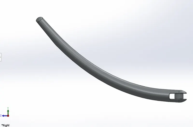
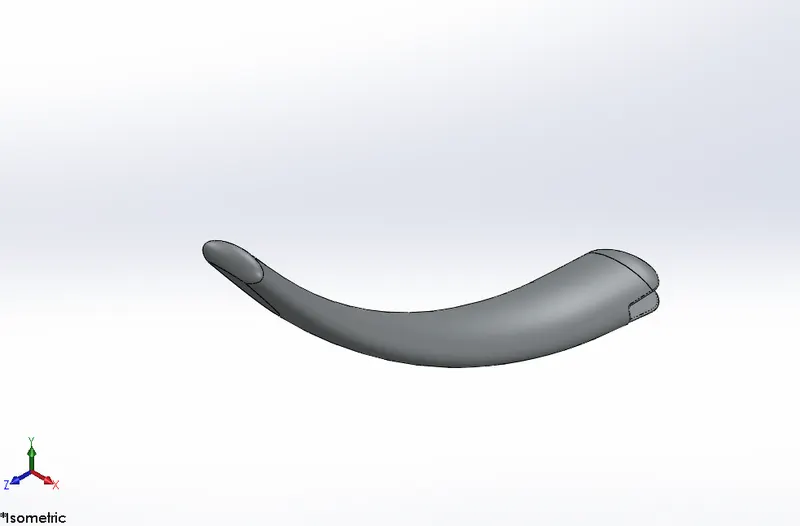
Fig13: Front View Fig14: Side View Fig15: Isometric View
A Chromium plate appearance was chosen for this part.
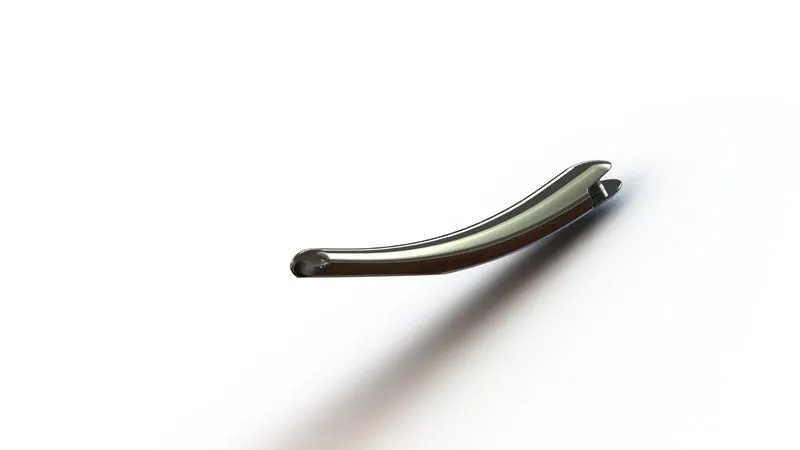
Fig16: Final Render
Front Fender
A fender is a part which incorporates the wheel well in a bike and helps prevent dirt and sand from flying out of the spinning wheel.
The curved portion of the fender was made using the Revolve Boss/Base feature (revolves a sketch or contour around an axis to create a solid feature).

Fig17: Revolve Boss/Base
Proper fillets were then added to smoothen the edges.
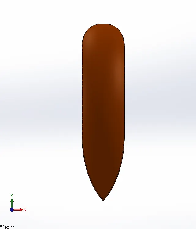
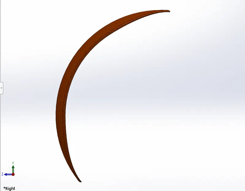
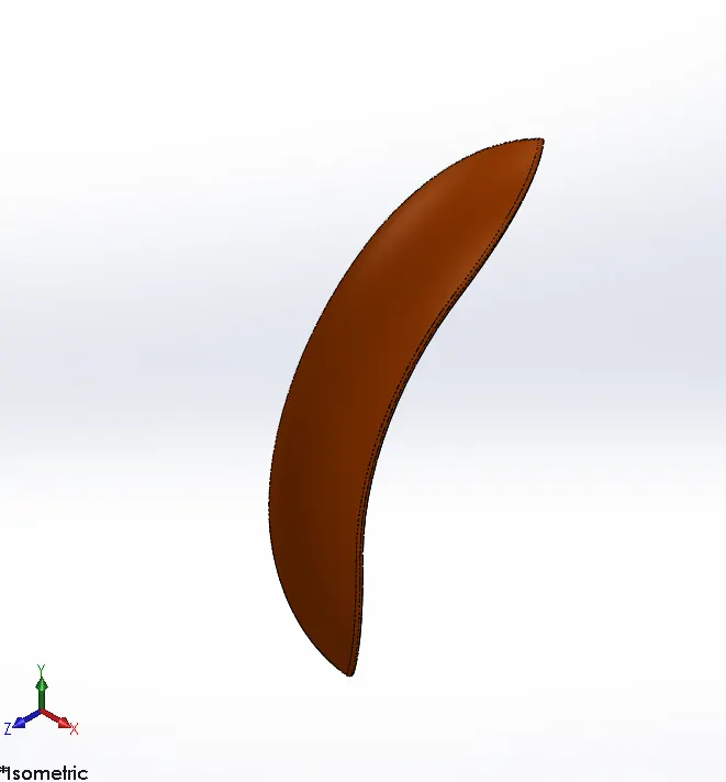
Fig18: Front View Fig19: Side View Fig20: Isometric View
A Sienna coloured painted appearance was given for this part.
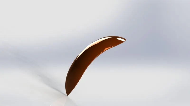
Fig19: Final Render
Rear Fender
The rear fender was done in a similar manner as that of the front. The wheel well in this part was made using the Shell feature, which helped in creating a thin-walled feature.
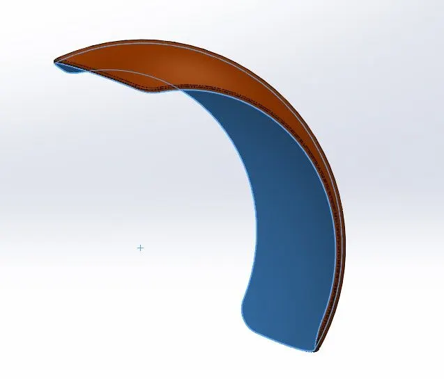
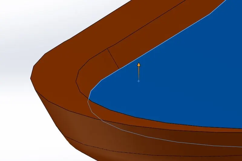
Fig20: Shell feature Fig21: Shelled part
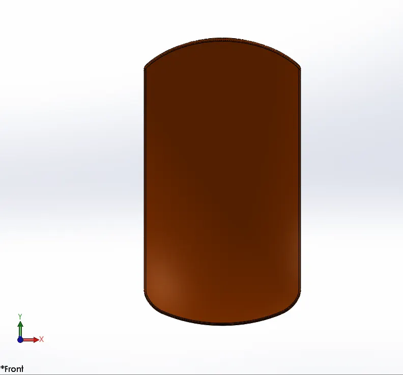
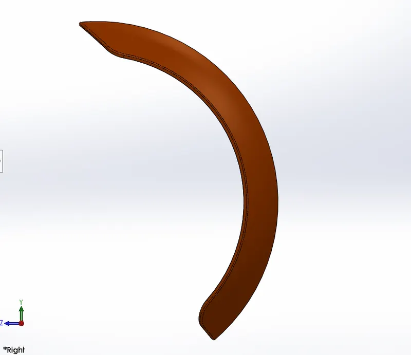
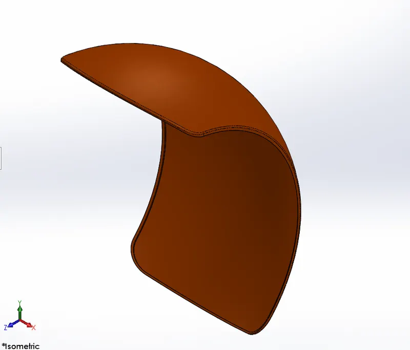
Fig22: Front View Fig23: Side View Fig24: Isometric View
A Sienna coloured painted appearance was given to this part.
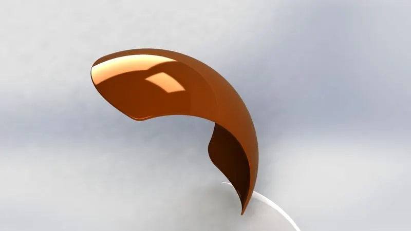
Fig25: Final Render
Chain
Known as roller chains, a typical chain drive transmits mechanical power in a motorcycle. It consists of a series of cylindrical pins held together by side plates and is driven by a toothed wheel called sprocket.
Consisting of 390 solid bodies (130 Pins and 260 Chain plates), this was the first complex modeling process in this stage.
The profile for the chain plates and the pins were made as sketches and then saved as Sketch Blocks. These blocks were then extruded thrice to design the cascading plates as well as the pins. These solid bodies were then patterned according to a specified path using the Curve Driven Pattern feature.
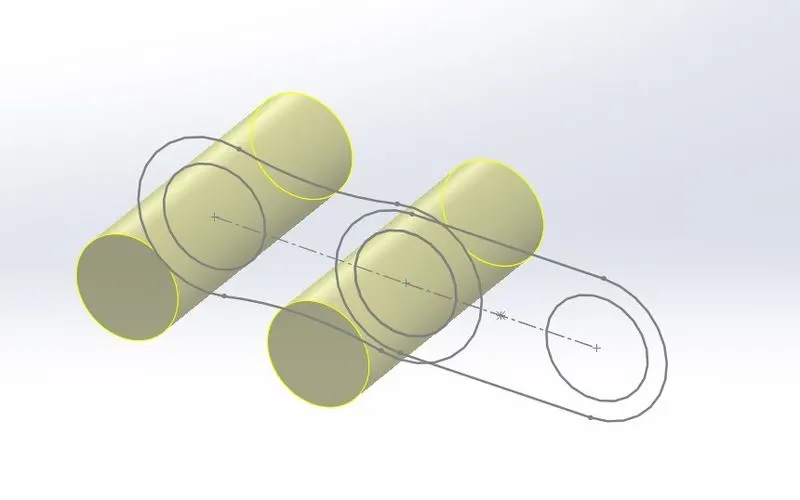
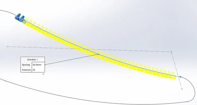
Fig26: Sketch Block Extrusion Fig27: Curve driven pattern
The chain links were patterned and stopped at four pivotal points along the path to ensure proper design. The continuity was maintained by adjusting the number of instances. The last link was not concentric with the pin and as such, the Delete Body feature was used to delete the link and then it was redrawn to ensure a proper design. The entire chain was then mirrored about the front plane (in this case, renamed to Midplane) to complete the model.

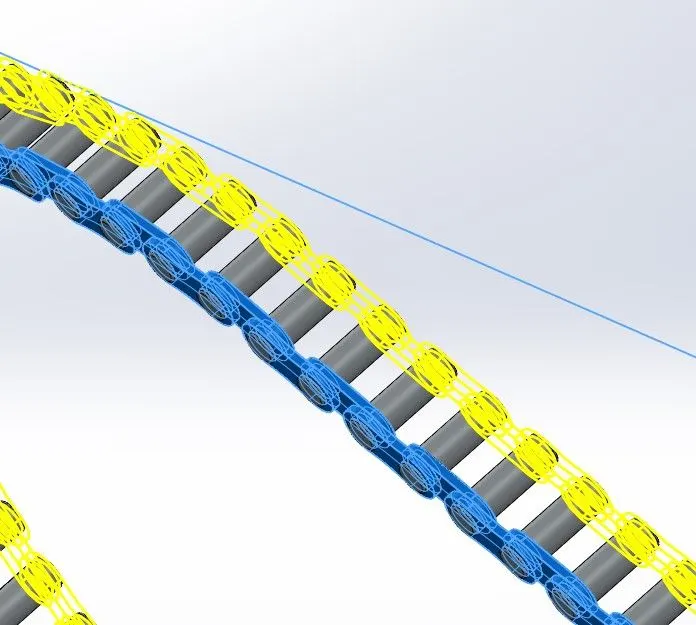
Fig28: Delete Body Feature Fig29: Mirror feature
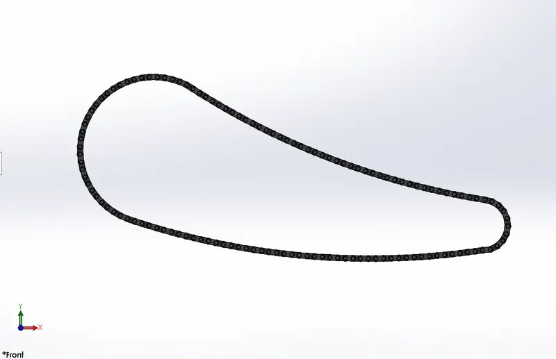
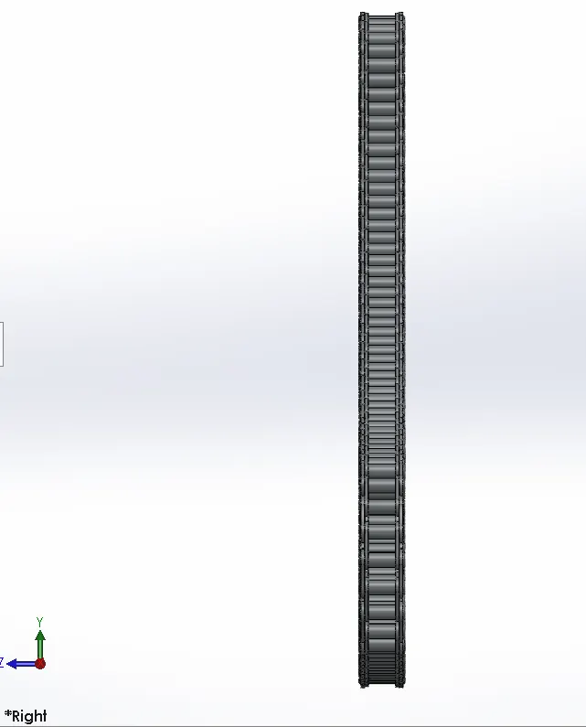
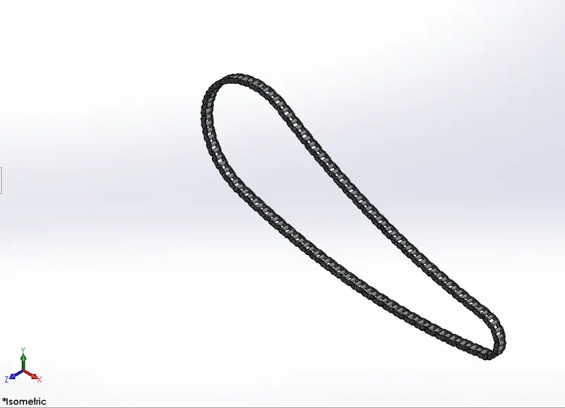
Fig30: Front View Fig31: Side View Fig32: Isometric View
A chromium plate appearance was given for this part.
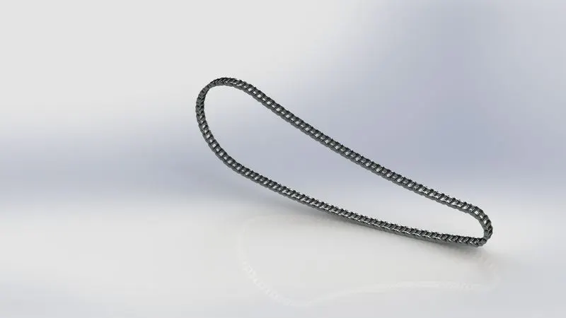
Fig33: Final Render
Oil Tank
The oil tank was designed using a combination of two solid body extrudes. The Combine feature (combines two or more solid bodies) was used with the common type operation which combined the two bodies by keeping only the portion which was common to both. The shell feature was used to make the part hollow.
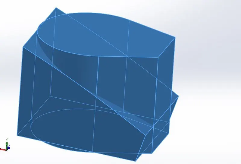
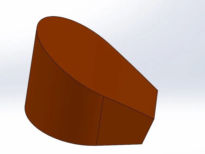
Fig34: Combine feature Fig35: Combined bodies
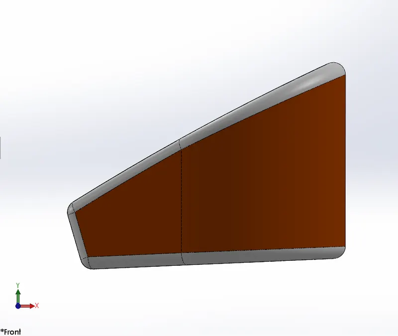
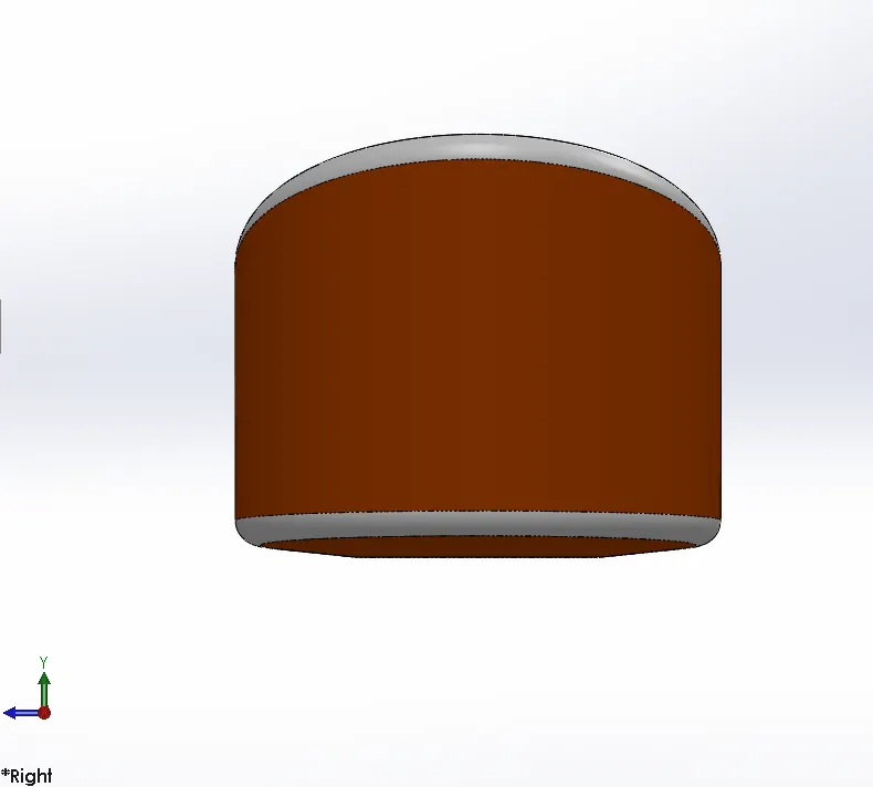
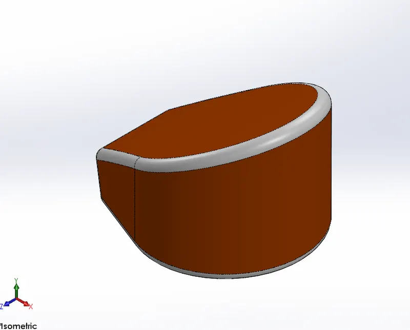
Fig36: Front View Fig37: Side View Fig38: Isometric View
A Sienna painted appearance was chosen for the body and a painted white colour for the filleted edges.
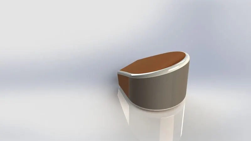
Fig39: Final Render
Pedal
A motorcycle pedal acts as both a footrest for the rider and as a gear lever.
The projections from the base of the pedal were capped off with a pointed end using the Chamfer feature. The ring structures along the projected bodies were made using the Linear Pattern feature.
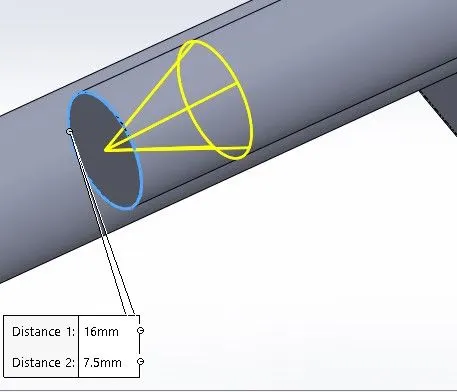
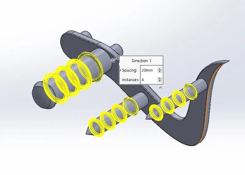
Fig40: Chamfer feature Fig41: Linear Pattern
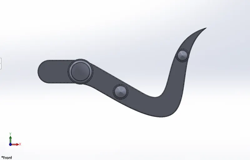
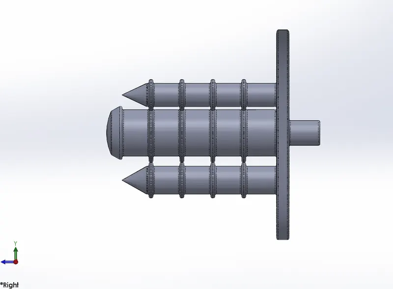
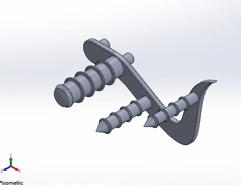
Fig42: Front View Fig43: Side View Fig44: Isometric View
A chromium plate appearance was applied to this part.
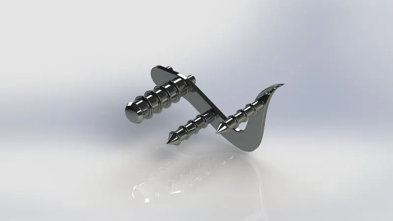
Fig45: Final Render
Front Wheel
The front wheel incorporated four solid bodies: Rim, Rotor, Calliper and Tire.
Using revolve and extrude features, the rim and its spokes were designed.
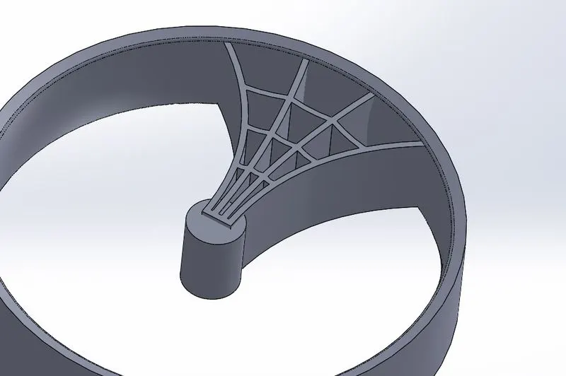
Fig46: Rim and spoke
The webbed design in the spoke is then cut from the front using the Cut Revolve feature. This produced a curvy design for the spokes. The spoke is then patterned around the rim using the Circular Pattern feature.
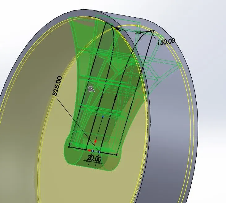
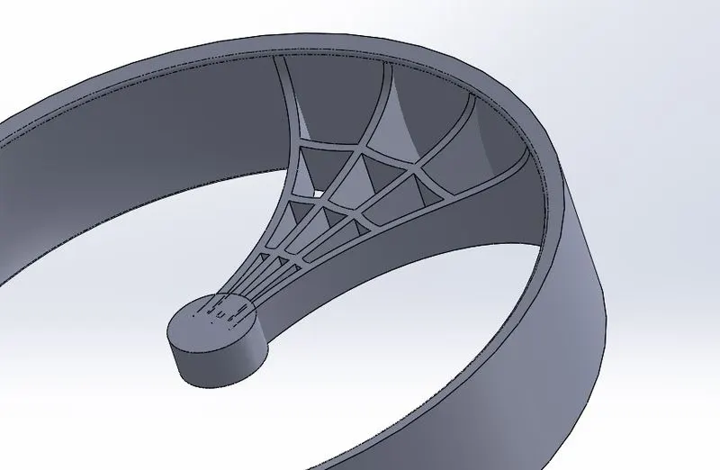
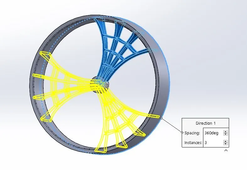
Fig47: Cut Revolve Process Fig48: Revolved cut part Fig49: Circular Pattern
The rotor, the calliper and the tire are designed in a similar manner, with the help of Revolve, Extrude and Cut Extrude features. The Calliper edges are smoothened using Chamfer and Fillet features.
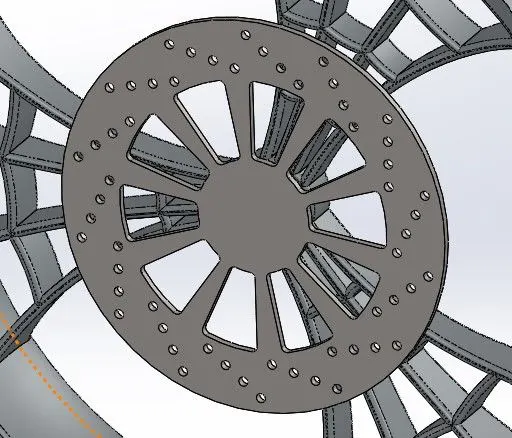
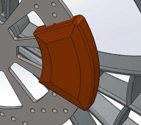
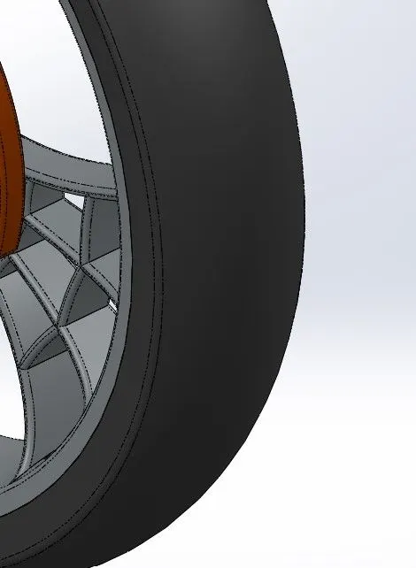
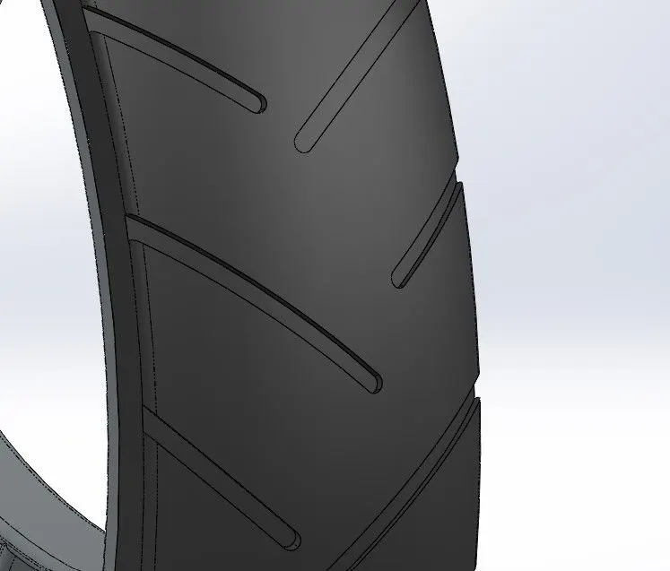
Fig50: Rotor Fig51: Calliper Fig52: Tire Fig 53: Tread Marks (using Cut Extrude)
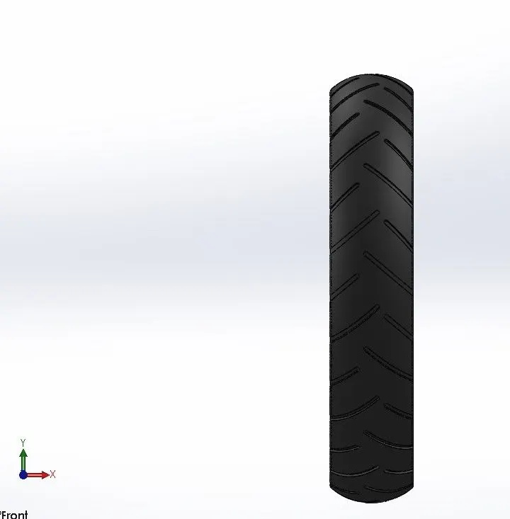
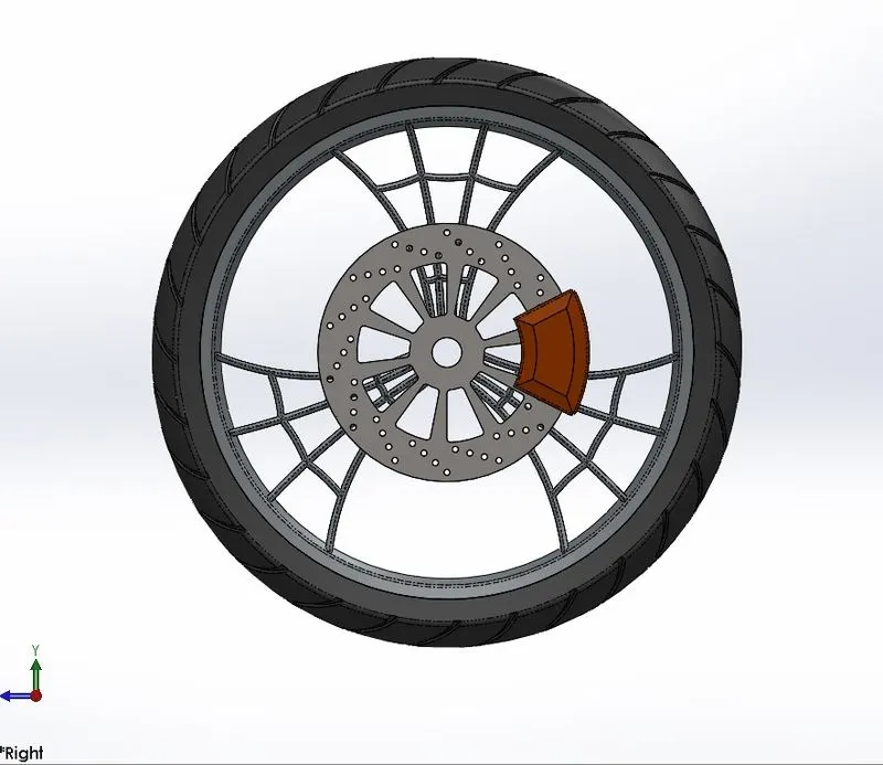

Fig54: Front View Fig55: Side View Fig 56: Isometric View
A chromium plate appearance was given for the rim, carbon steel for the rotor, a sienna painted appearance for the calliper and matte rubber for the tire.
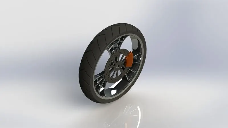
Fig57: Final Render
Rear Wheel
The design of the rear wheel was similar to that of the front. The wheel however, was wider and had an extra component too: Sprocket.
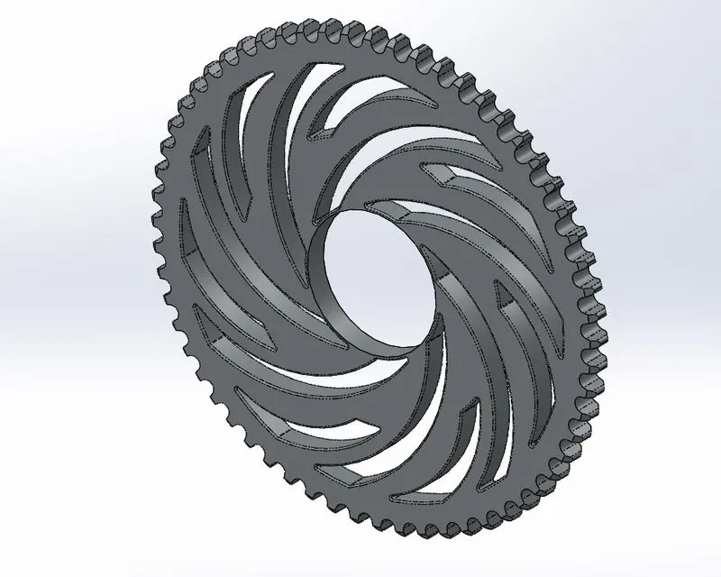
Fig58: Sprocket
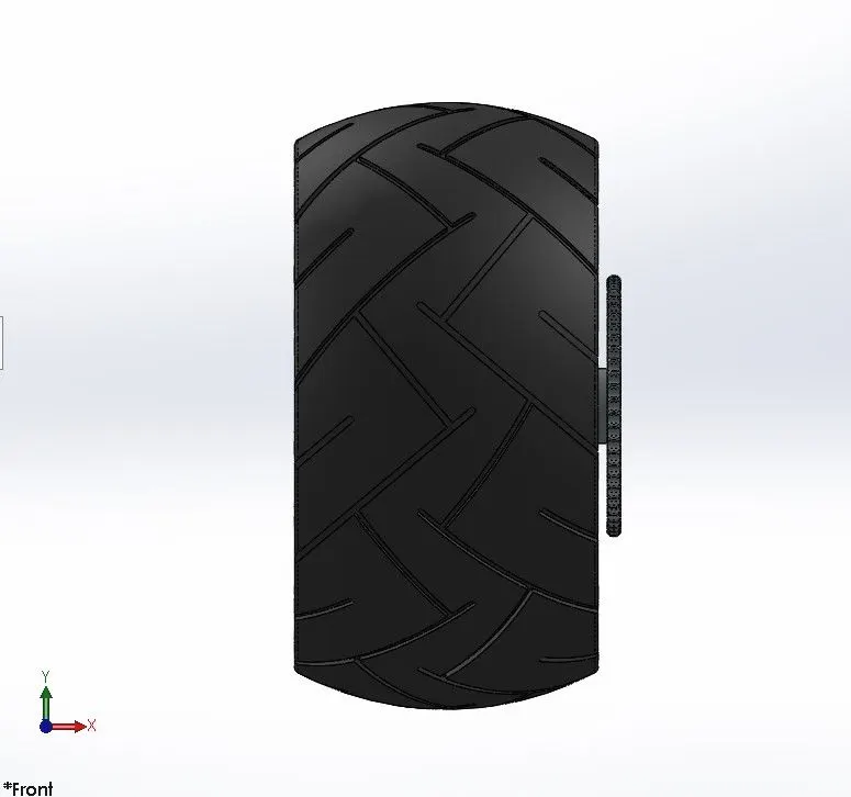
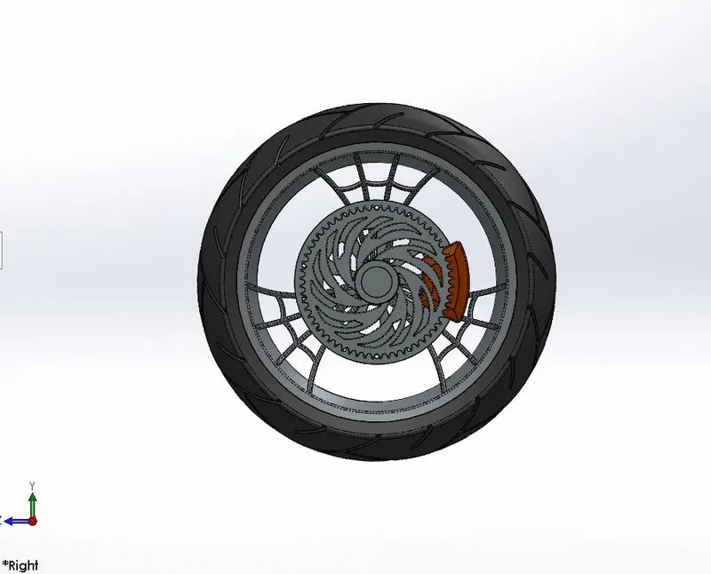
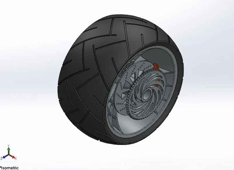
Fig59: Front View Fig60: Side View Fig61: Isometric View
The sprocket was given a chromium plate appearance.
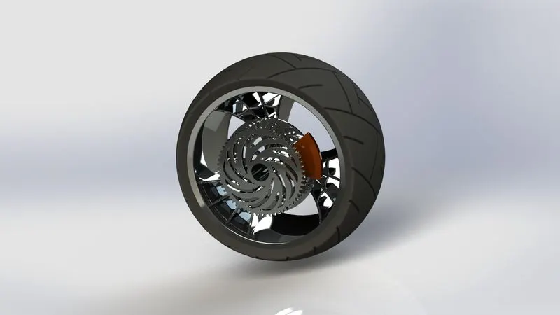
Fig62: Rear Wheel
Front Fork
The front fork of a motorcycle incorporates the shock absorbers, the handlebar, headlights and connects the front wheel. The forks of a chopper bike are distinctive due to their modified lengths and steering angles.
The Move/Copy Body feature was used to translate the light holder towards the middle of the fork. A Projected Curve feature (calculates a curve based on the intersection of two sketch planes) was used to set up a path for designing the handlebar using Sweep feature. The curve acted as the guide curve for the sweep.
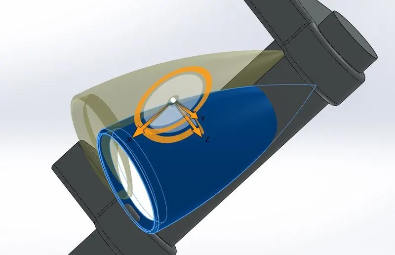

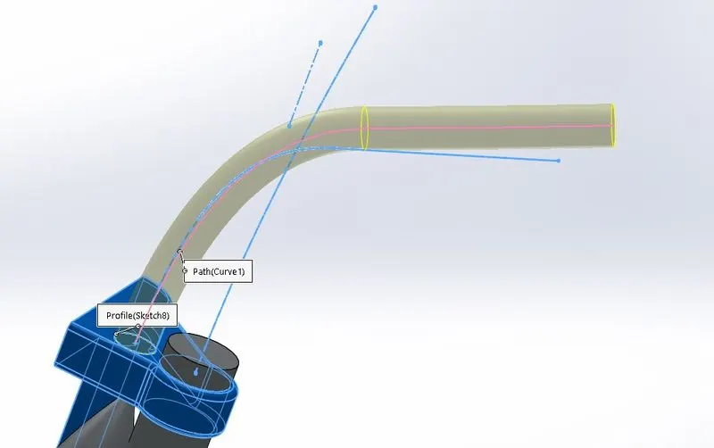
Fig63: Move/Copy Body Fig64: Projected curve (yellow) Fig65: Sweep feature
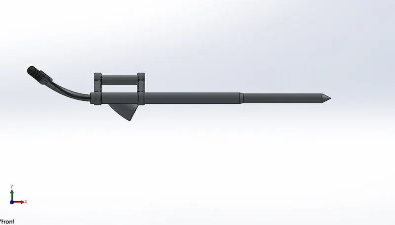
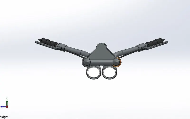
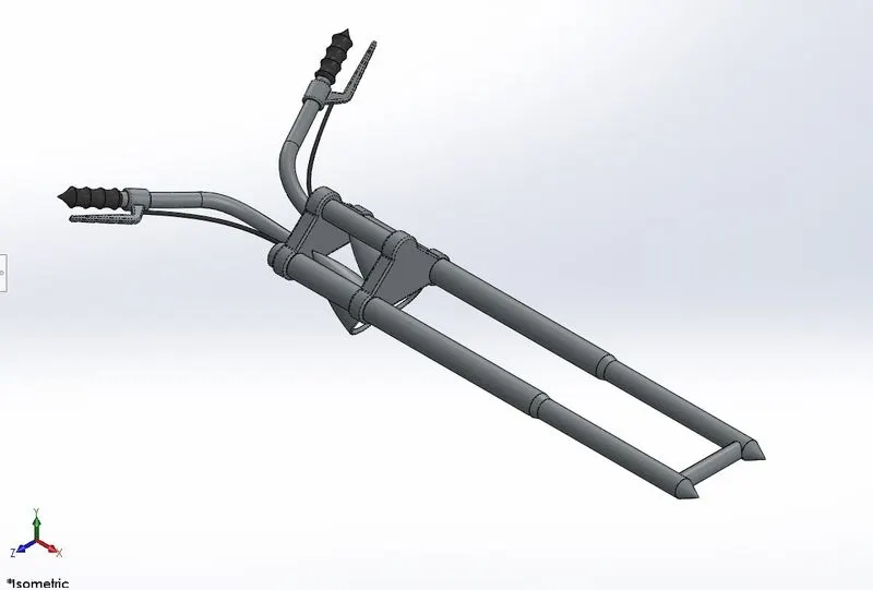
Fig66: Front View Fig67: Side View Fig68: Isometric View
The front face of the light holders was given an Area Light appearance to aid it during rendering.
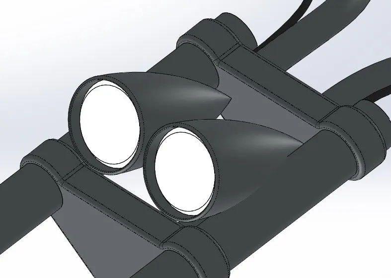
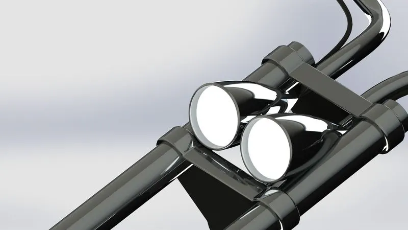
Fig69: Area lights (SW window) Fig70: Area lights (Rendered)
A chromium plate appearance was given to the fork and glossy rubber appearance for the handle grips and brake wires.
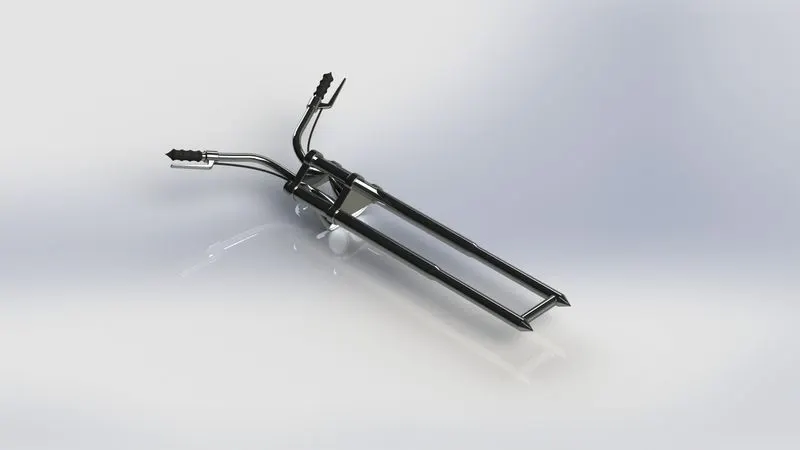
Fig71: Final Render
Chassis
The chassis is the skeleton or base portion of a bike which serves as a central portion connecting all other parts. It provides stability to the vehicle.
For designing the chassis, a 2-d image was imported into the solidworks window using the Sketch Picture tool. It was provided a transparency and was used as a reference to begin the sketching process.
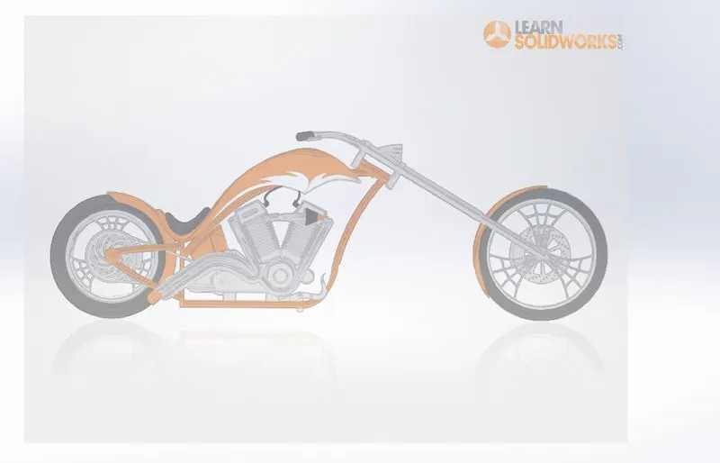
Fig72: 2D image of the chopper
The chassis incorporated brackets and platforms to incorporate other components during the assembly.
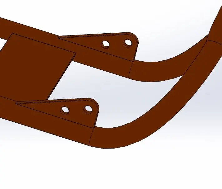
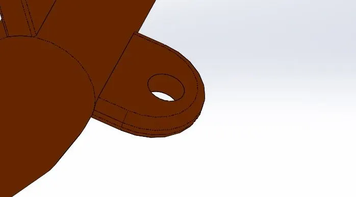
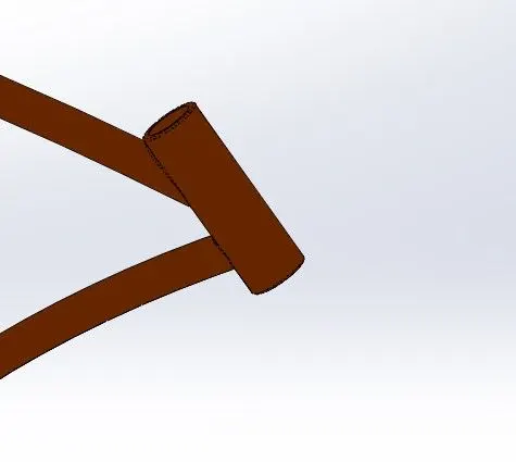
Fig73: Provision for pedals Fig74: Provision for kickstand Fig75: Provision for front fork
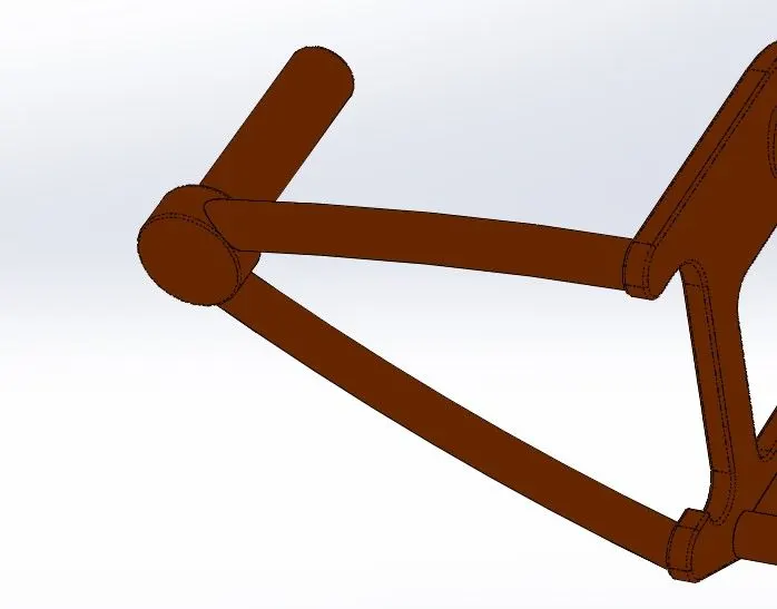
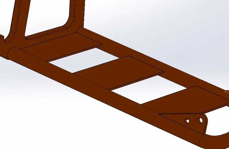
Fig76: Provision for Rear wheel Fig77: Base for the Engine
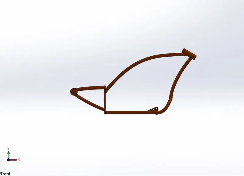
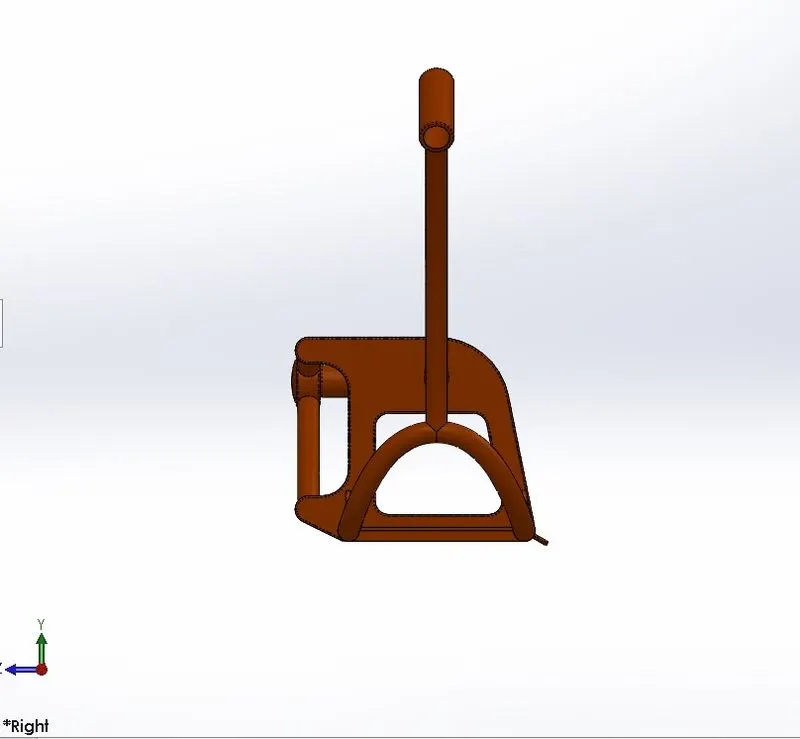
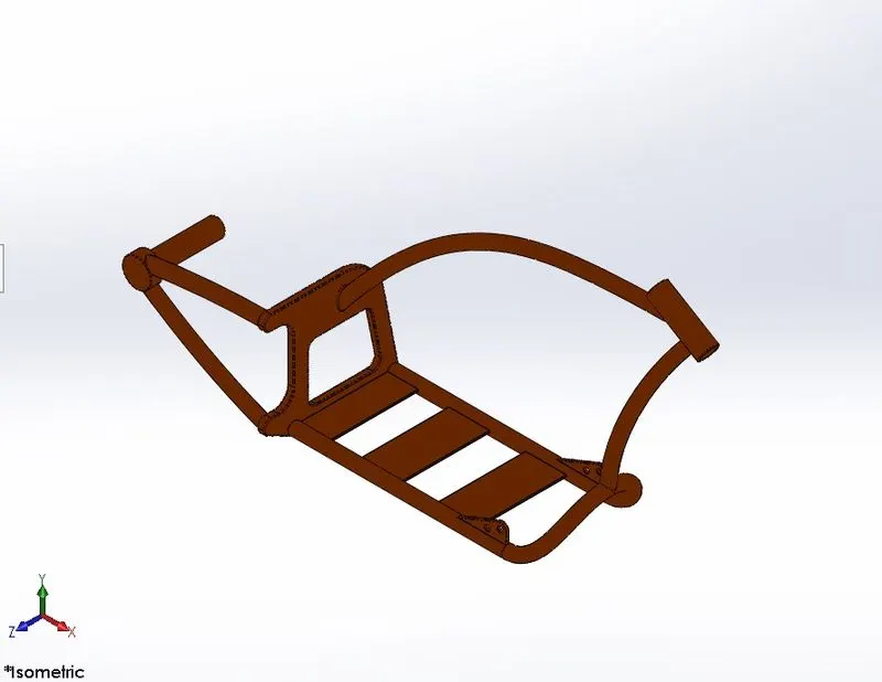
Fig78: Front View Fig79: Side View Fig80: Isometric View
A sienna painted appearance was given to this part.
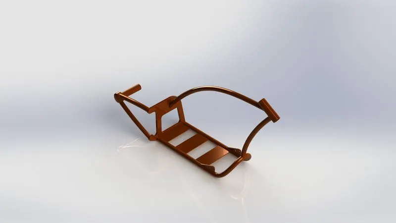
Fig81: Final Render
Engine
A V-2 engine (2 cylinder) has been used in this model. Accordingly, two exhaust pipes were also designed.
The cylinder block was designed using extrude feature and the fins were designed using linear pattern. After modeling one block, the other was mirrored. The spark plug wires were designed using sweep feature which was earlier used in the handle design.
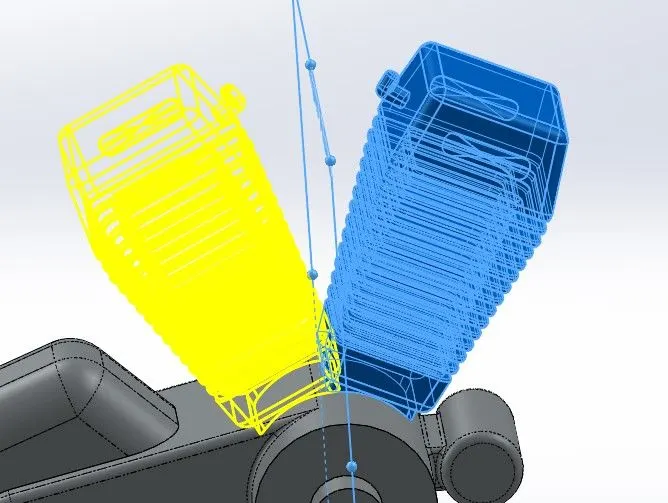
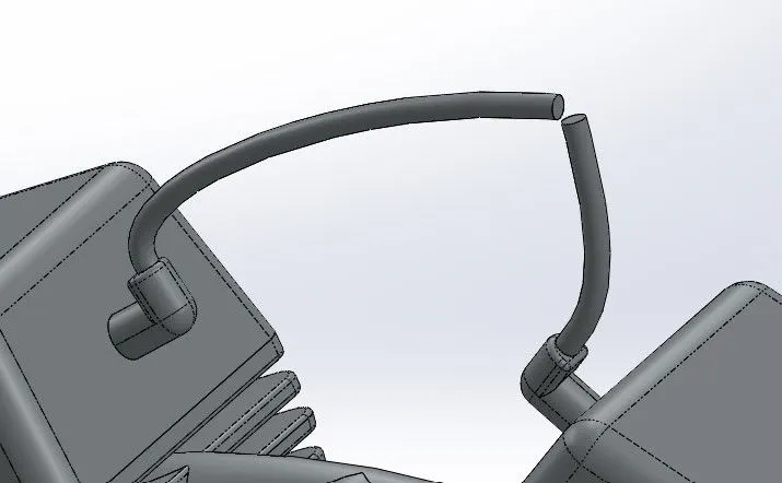
Fig82: Mirroring the cylinder block Fig83: Spark plug wires (Sweep feature)
A new feature used here was Composite Curves. This feature enabled two different projected curved to be combined into a single curve, which was helpful for the design of the exhaust pipes. The split feature was used to remove material from the end of the exhaust pipe to give it an angular cut appearance.
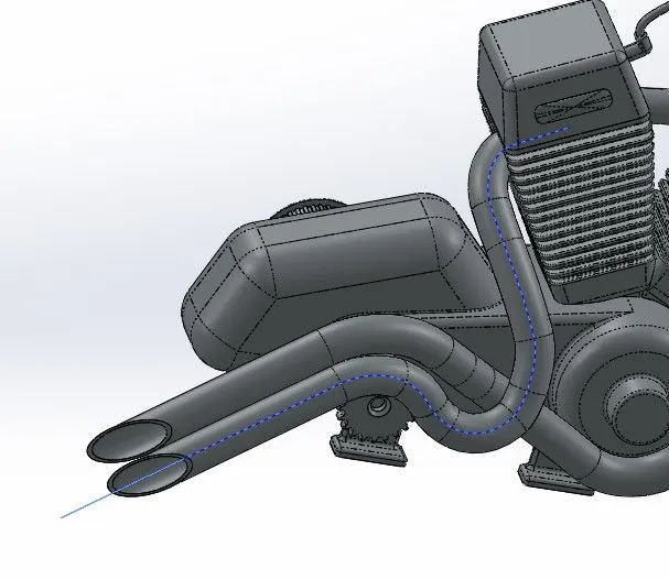
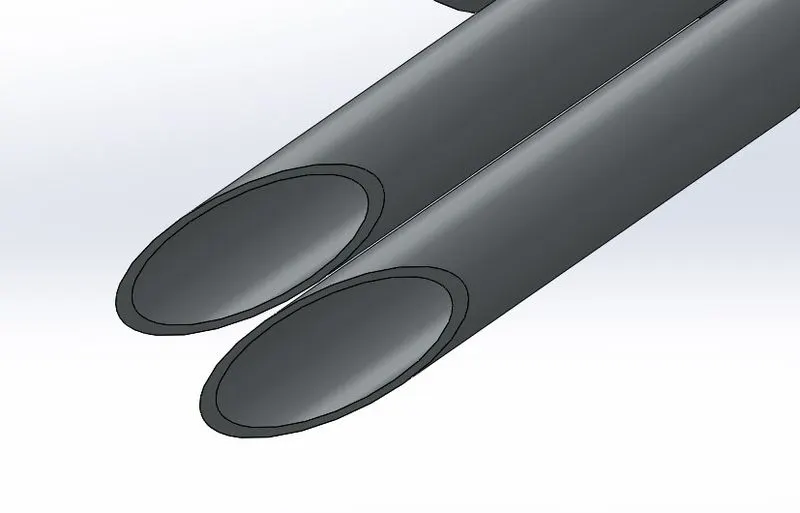
Fig84: Composite curve used for designing the exhaust pipe Fig85: Exhaust tips
Then engine has components which were made for connecting with other parts during the assembly. These parts are shown in the images below.
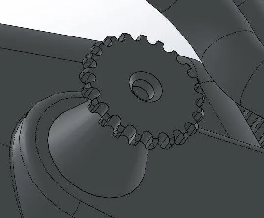
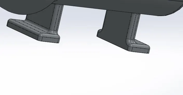
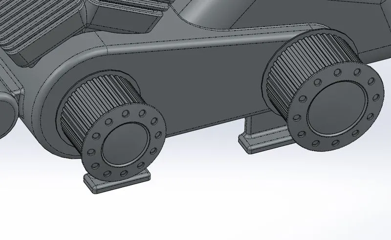
Fig86: Sprocket for chain Fig87: Legs for mounting the engine on the Chassis Fig88: Rotors for the transmission belt
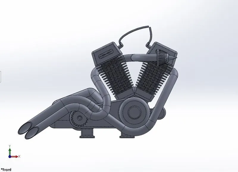
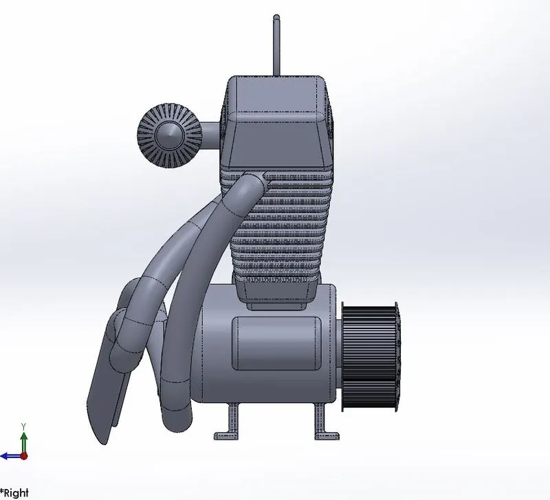
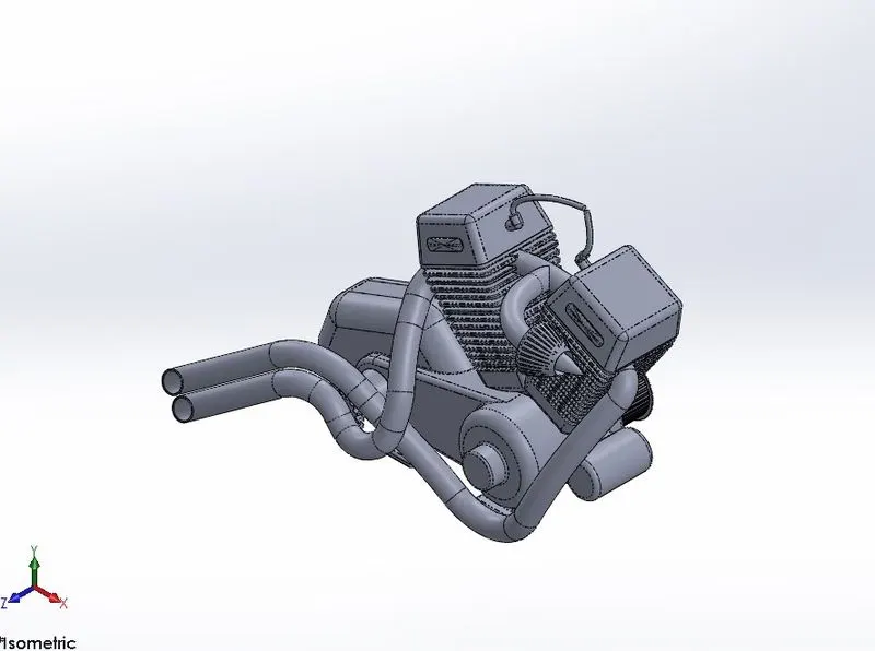
Fig89: Front View Fig90: Side View Fig100: Isometric View
A chromium plate appearance was given for this part.
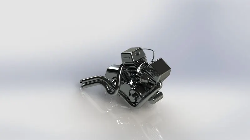
Fig101: Final Render
Gas Tank
The top portion of the bike, which incorporates the rider seat.
For this part, a variety of surface modeling features were used. Surface sweep (creates a surface based on a profile and a path) feature was used to create the top surface of the gas tank. To trim it according to a specified shape, the Surface Trim feature was used. To provide a depth for the top right corner of the gas tank, the existing edge along with newly drawn guide curves were used in the Surface Loft feature (creates a lofted surface between two or more profiles). To provide cover for the rest of the gas tank, the Boundary surface feature was chosen. To ensure proper accuracy of the boundary surface, guide curves were chosen along the path.
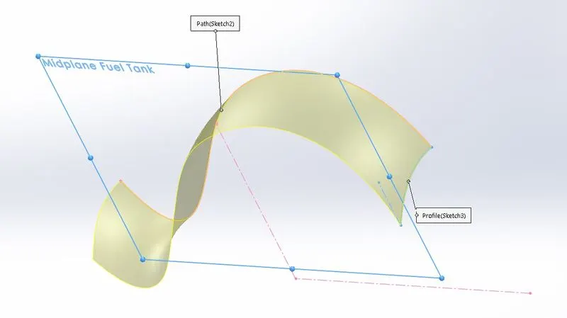
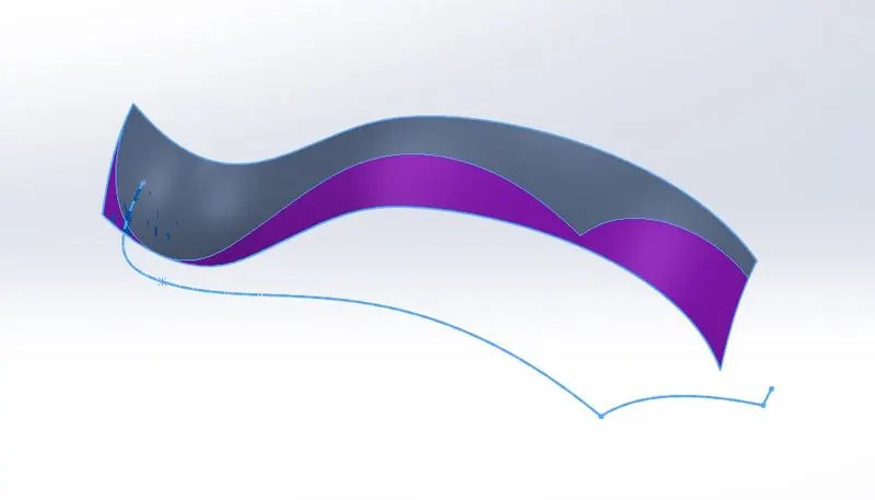
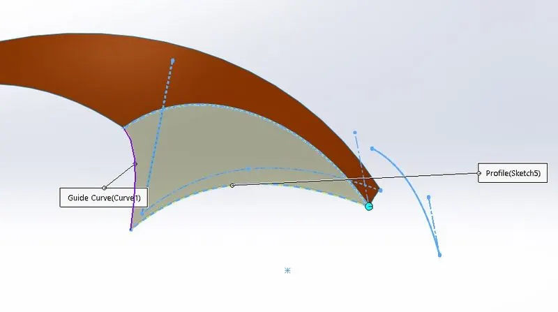
Fig102: Surface Sweep Fig103: Surface Trim Fig104: Surface-Loft
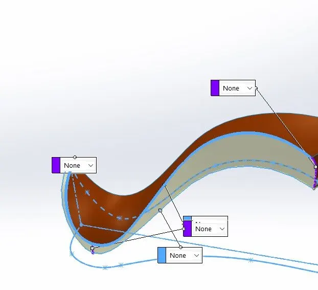
Fig105: Boundary Surface
The entire surface was then mirrored using the midplane. To ensure proper tangency of the mirrored parts, the Surface Knit feature (combines two or more adjacent, non-intersecting faces together) was used.
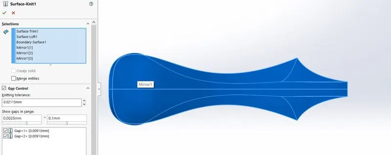
Fig106: Surface Knit
The split feature was used to separate the area for creating the seat of the bike. The split surface was then extrude using the Surface Extrude feature.
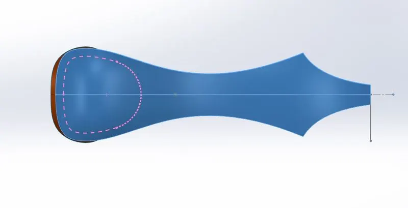
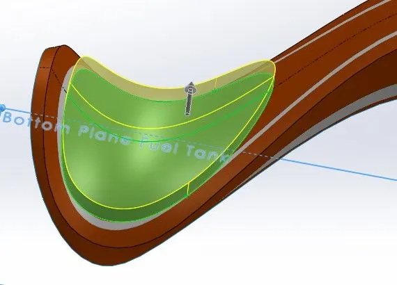
Fig107: Splitting the area for the seat Fig108: Surface Extrude feature
Finally, a recess was created using the Cut Sweep feature. This portion was done to allow the gas tank to rest upon the chassis during the assembly.
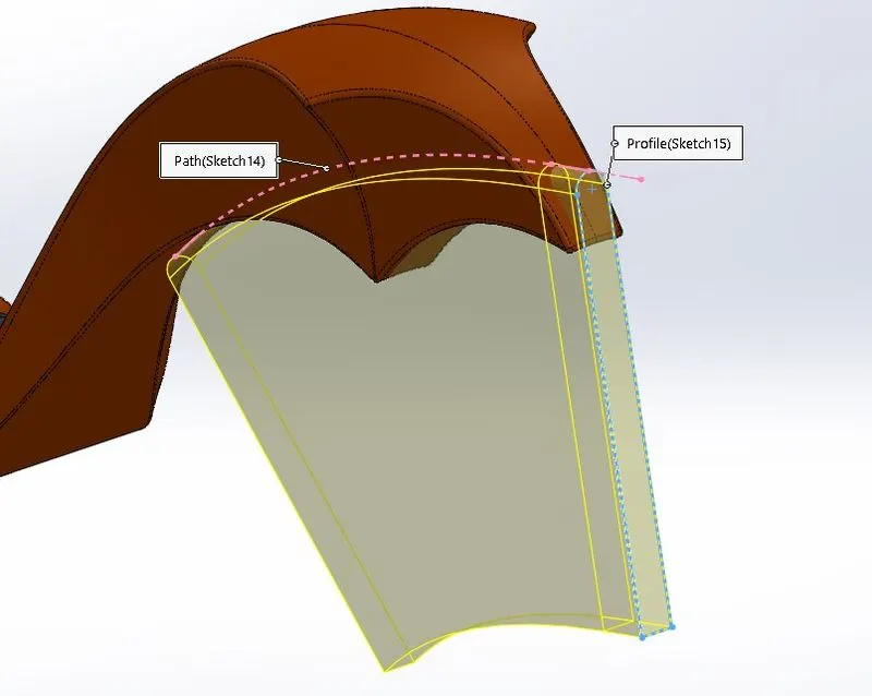
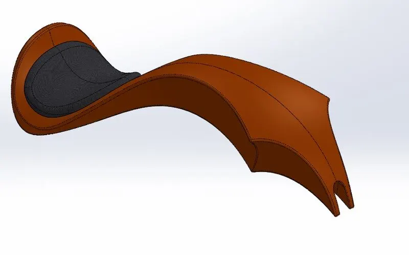
Fig109: Cut Sweep feature Fig110: Dotted line (middle) indicating a perfect knit
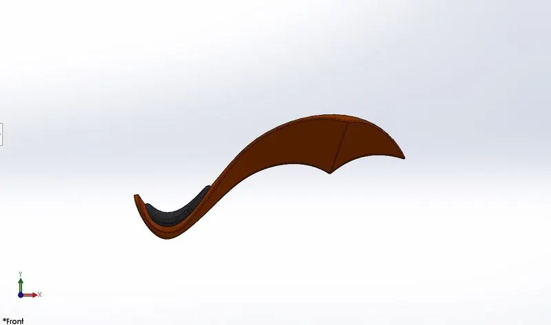
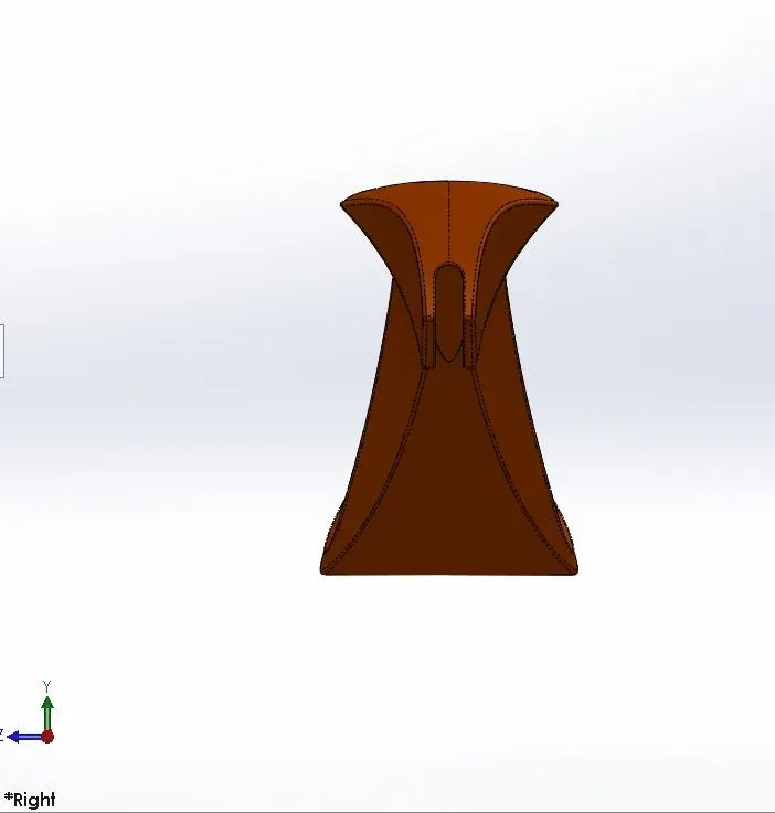
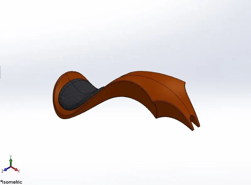
Fig111: Front View Fig112: Side View Fig113: Isometric View
A Sienna painted appearance was given to the gas tank and a grey cotton appearance for the seat.
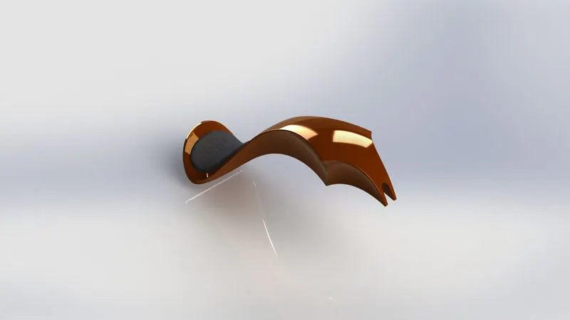
Fig114: Final Render
ASSEMBLY
An assembly a combination of parts or components that have a specified relation to each other. This relation is termed as a Mate. Two mating parts in Solid works can have various mating relations based on user specifications and geometry.
The following are the types of mates used in this project:
STANDARD MATES:
- Coincident: The mating parts are coincident with each other based on the coincidence of a surface or the sketch plane.
- Parallel: The mating parts have a surface or plane which are parallel to each other.
- Tangent: The mating parts (one of which must have a spherical surface) are tangent to each other
- Concentric: The mating parts (having circular sketches or spherical surfaces) are mated to the same centre point.
- Distance: The mating parts are separated by a specified distance
- Angle: The mating parts form a specified angle between them.
ADVANCED MATES:
- Width: The mating parts are specified by their widths and accordingly constrained with certain conditions (centred, percentage etc)
- Angle: Like the standard angle mate, except this mate can be specified with an angle range between which the parts can move.
Assembling the parts
Chassis: The chassis was imported into a new assembly window. The part was by default fixed in the assembly environment.
Engine: The Engine was the second part to be imported. To fix the part, certain constraints needed to be added with reference to the chassis. A Coincident mate was added in between the bottom surface of the left corner leg beneath the engine and the top surface of the first platform in the chassis. This restricted the longitudinal motion of the engine. In order to restrict the lateral motion, a Distance mate was added between the side faces of the previously mated leg and platform, with a specified distance.
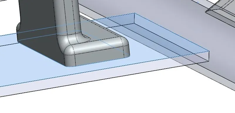
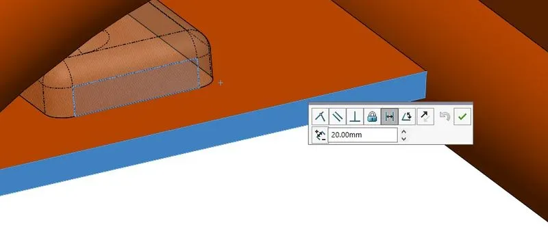
Fig115: Coincident Mate Fig116: Distance Mate
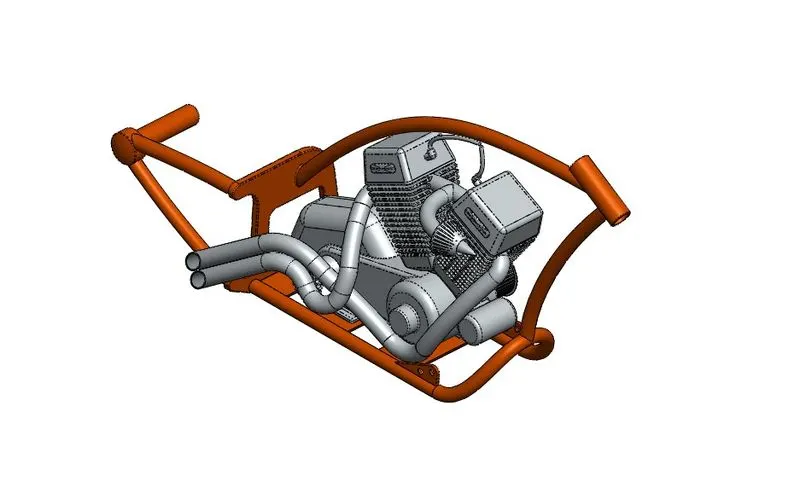
Fig117: Engine-Chassis Assembly (Isometric view)
Pedal: As mentioned before, a provision was provided to incorporate the pedal into the chassis. The connecting pins of the pedal and the chassis bracket holes were mated using a Concentric mate feature. The other pedal was made using the mirror option in the assembly ribbon.
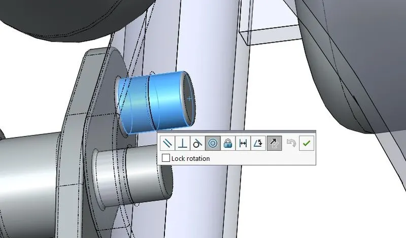
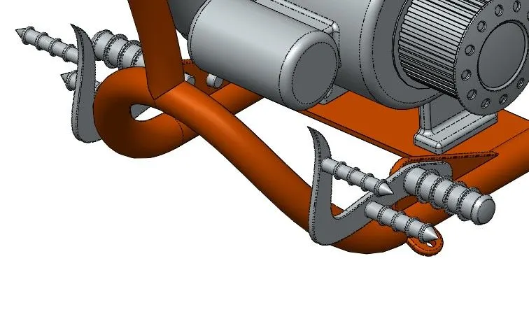
Fig118: Concentric Mates Fig119: Mirrored pedal
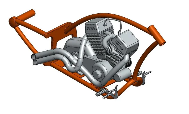
Fig129: Chassis-Pedal Assembly (the exhaust pipes were redesigned to avoid any interference with the pedal)
Kickstand: The kickstand was assembled to the extruded portion on the left side of the chassis using a concentric relation. The movement of the kickstand was determined using an Advanced Angle Mate.
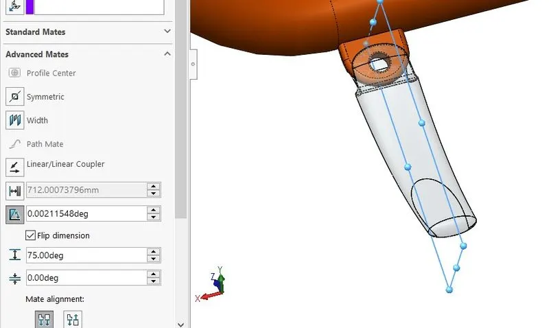
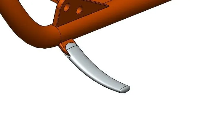
Fig130: Advanced Angle Mate Fig131: Chassis-Kickstand Assembly
Transmission belt: The transmission belt was fixed, first using a Width Mate (advanced) by specifying the parallel surfaces (side) of both the belt and the rear rotor on the engine. The longitudinal motion was constrained using an Angle mate between the upper surface of the belt and that of the base portion of the engine.
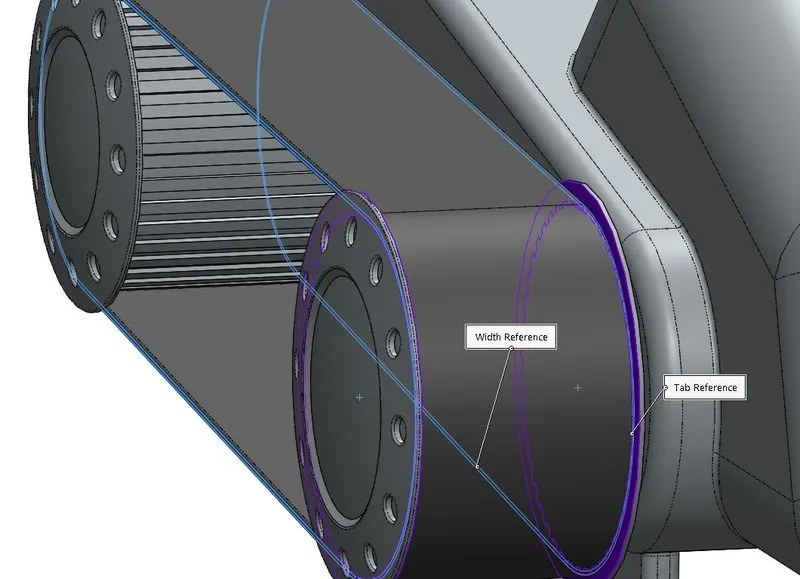
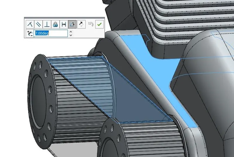
Fig132: Width Mate Fig 133: Angle mate
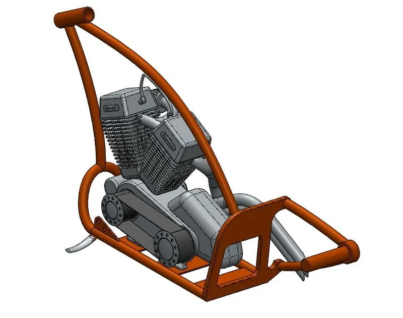
Fig134: Engine-Transmission belt Assembly
Oil Tank: The oil tank is assembled to the engine using three coincident mates (two of them between surfaces and one between planes)
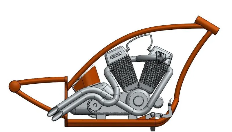
Fig135: Engine-Oil Tank Assembly
Rear wheel: Apart from the concentric mate provided to position the wheel behind the chassis, a Parallel mate is also applied between their right planes to prevent the wheel from rolling and thereby misplacing the calliper.
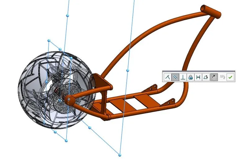
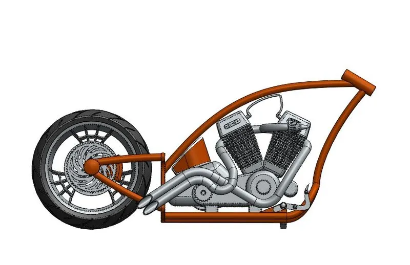
Fig136: Parallel mates Fig137: Chassis-Rear wheel Assembly
Rear Fender: The rear fender has a concentric relation with the rear wheel and a coincident and parallel relation with the chassis.
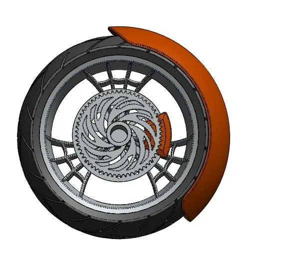
Fig138: Rear fender Assembly
Chain: The rear end of the chain was fixed using a concentric mate (between the rear arc in the chain sketch and the sprocket hole) and a width mate with the rear sprocket. Using a parallel relation with the chassis, the front end of the chain was also fixed. The Chassis was modified to avoid interference from the chain.
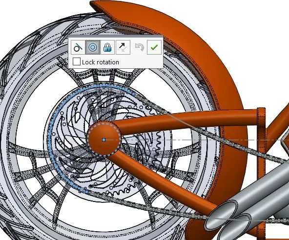
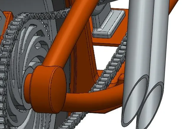
Fig139: Concentric Mate (sketch and surface) Fig140: Chassis modification to avoid interference
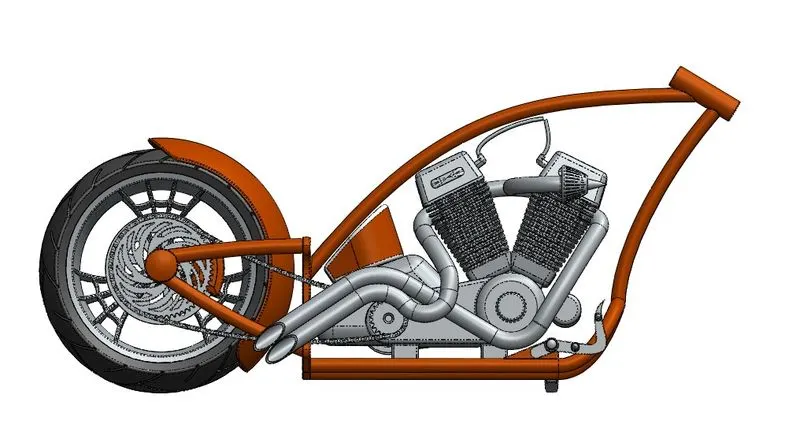
Fig141: Chain assembly
Gas Tank: Using a couple of coincident mates and a distance mate between the planes, the gas tank was mated to the chassis.
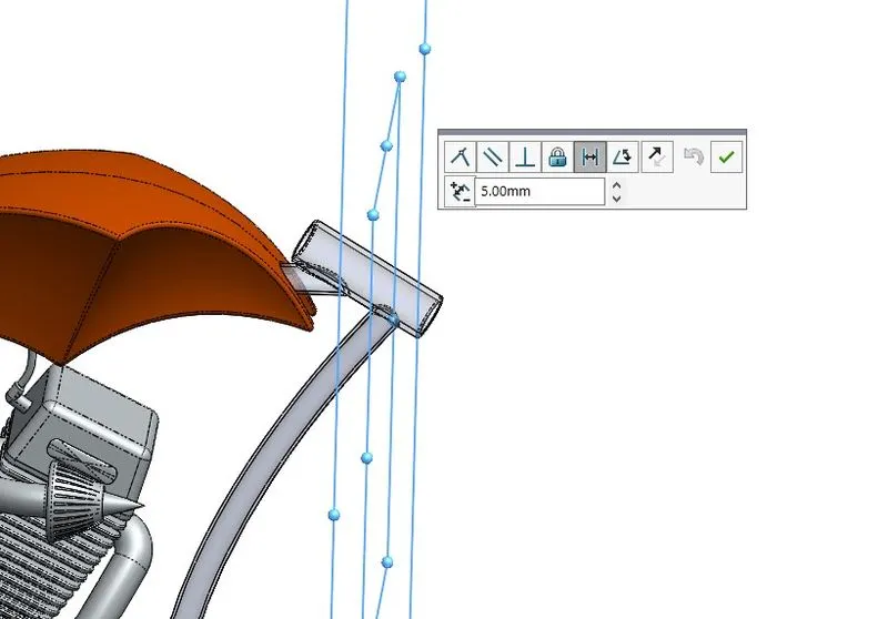
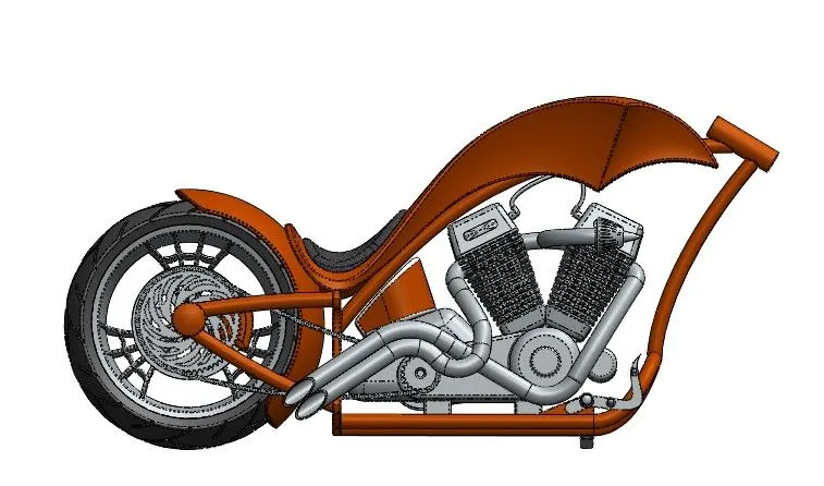
Fig142: Distance mate Fig143: Chassis-Gas tank assembly
Front Fork: Apart from using a width and concentric mate with the chassis, the movement of the front fork was made realistic by using an advanced angle mate (like the kickstand)
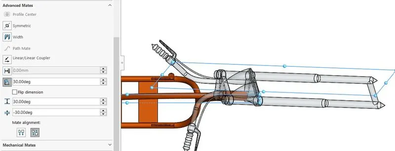
Fig144: Advanced angle mate
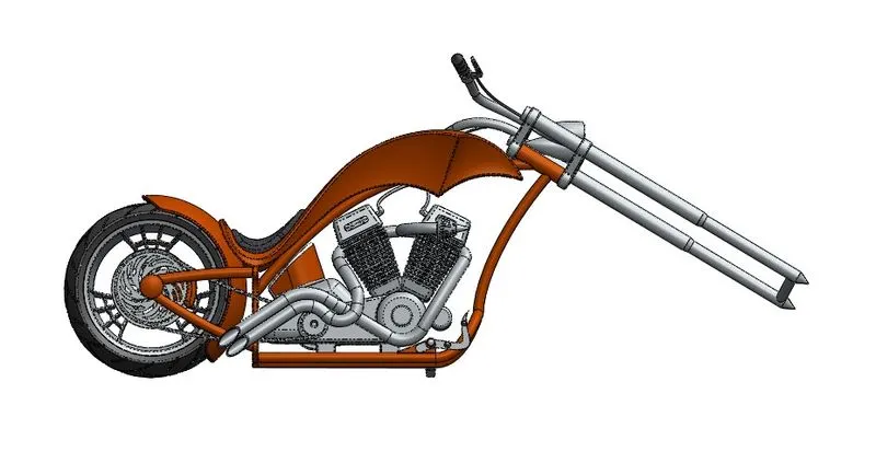
Fig145: Chassis-Front Fork Assembly
Front Wheel: The front wheel was constrained by using a concentric mate with the front fork.
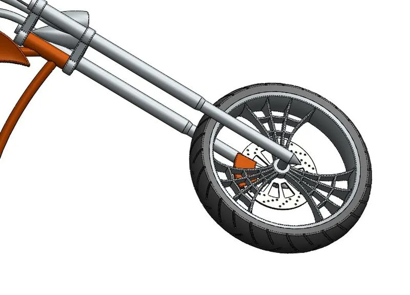
Fig146: Front Fork- Front Wheel Assembly
Front Fender: The front fender was mated to the front wheel and the front fork by using coincident mates.
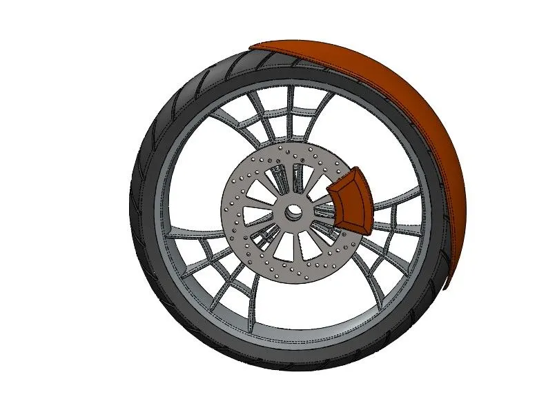
Fig147: Front Fender Assembly
With the assembly of the front fender, the assembly of the chopper was completed.
Before the final render, to ensure that the model does not appear to be floating, a Tangent mate was applied at the contact points of the rear wheel, the front wheel and the kickstand.
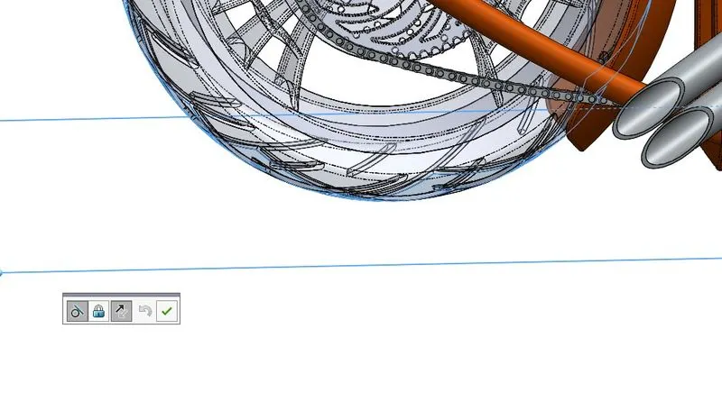
Fig148: Tangent mate
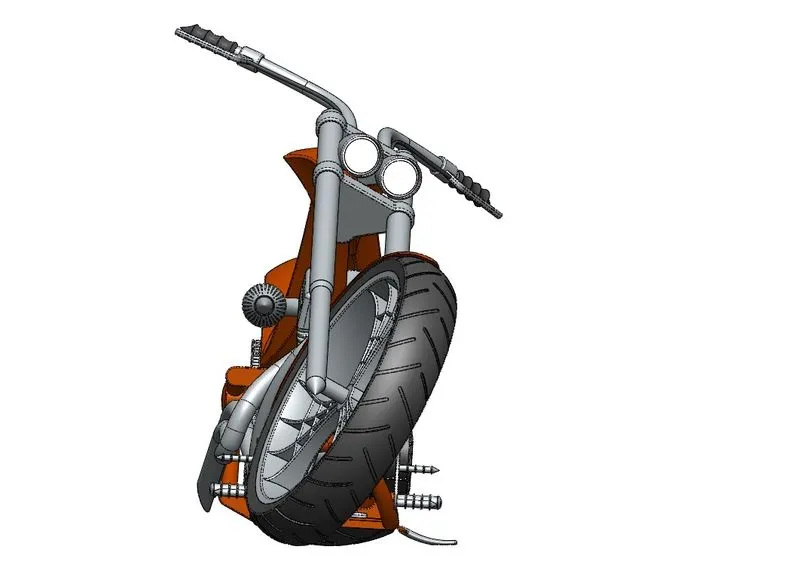
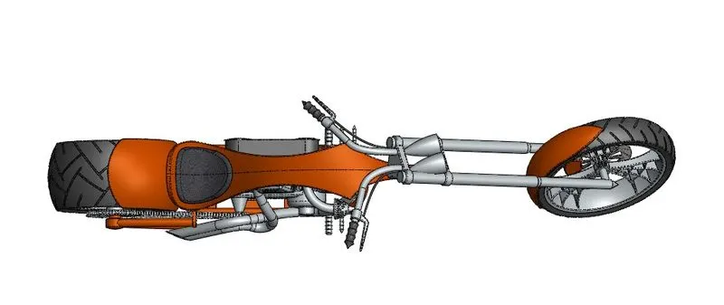
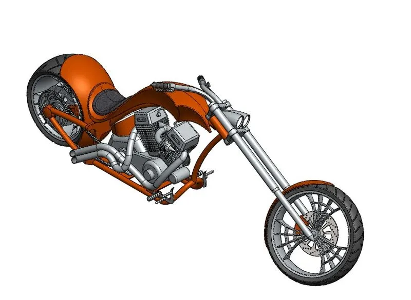
Assembled model with standard views
Front (Fig149)
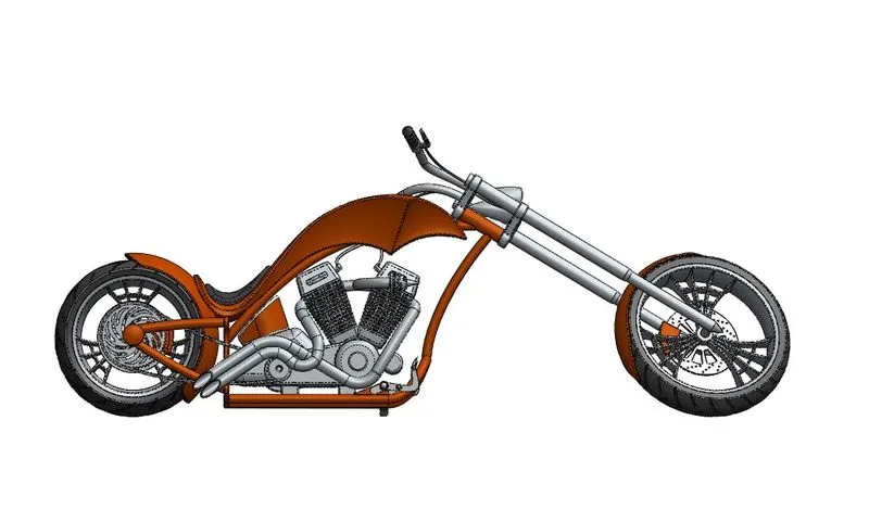
Side (Fig150)
Top (Fig151)
Isometric (Fig152)
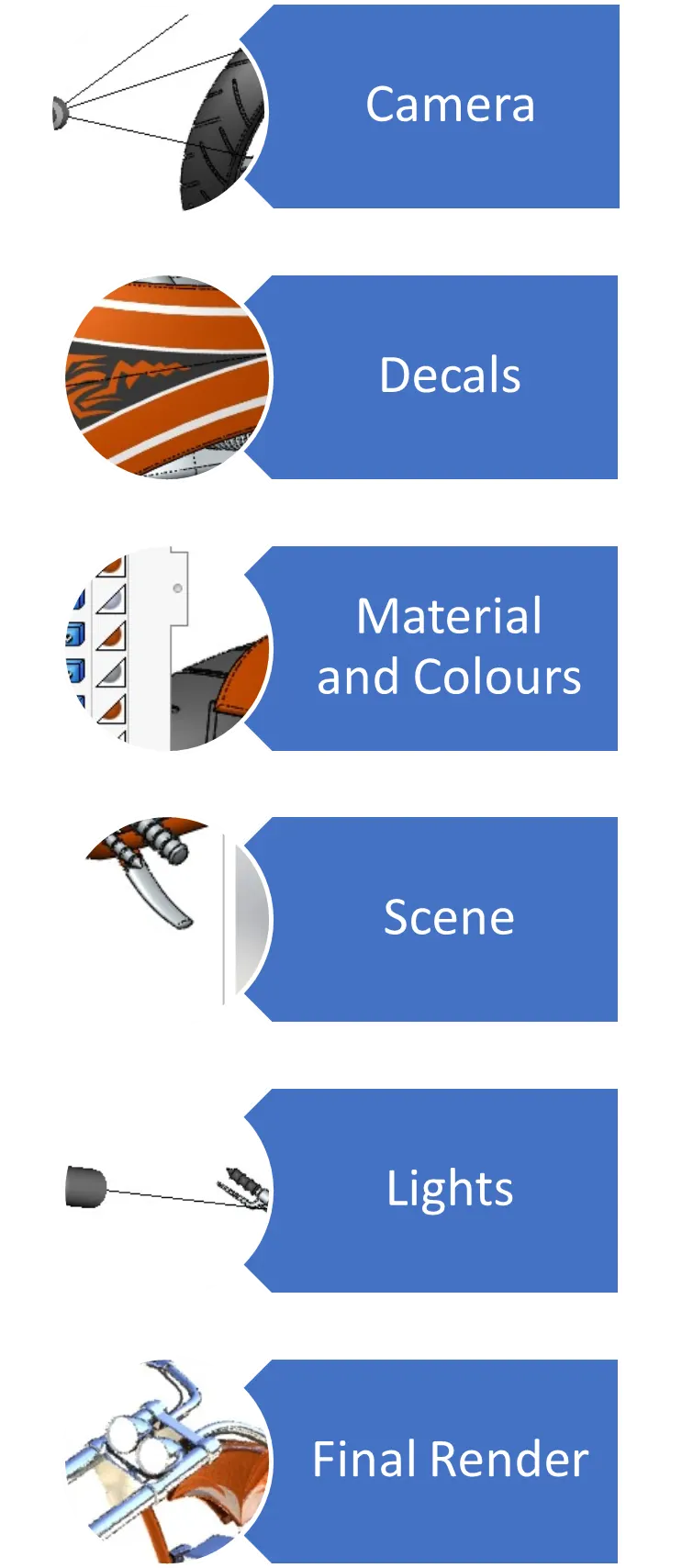
RENDERING
This stage incorporated visual tuning to make the final product presentable. The rendering is done using the Photoview 360 add in.
Camera Setup: The first stage was to set up a camera so as to project the bike in a realistic background.
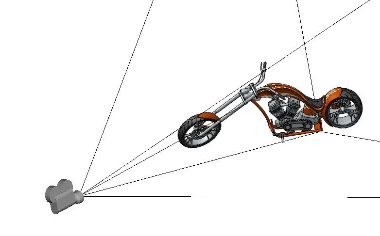
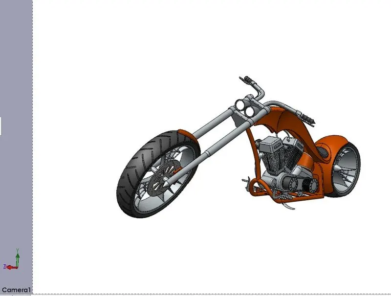
Fig153: Camera setup Fig154: Camera Setup View
Decals: A decal is an imprint on a surface depicting a name or a logo. Decals have been added to the gas tank, rear fender, and the oil tank in this project.
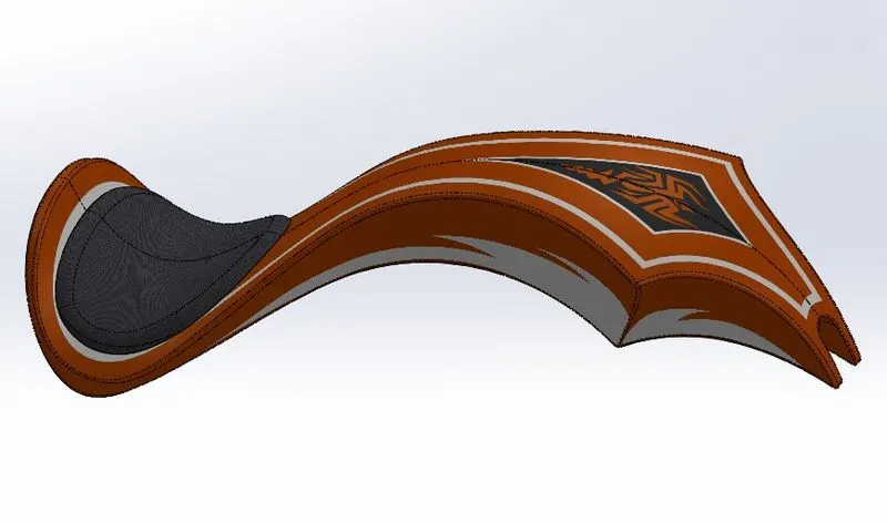
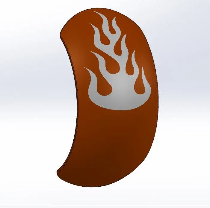
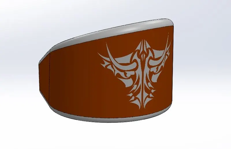
Fig155: Gas Tank Decal Fig156: Rear Fender Decal Fig157: Oil Tank Decal
Material and Colours: Appropriate materials and colour schemes have been added to individual parts as can be seen from earlier parts of this report.
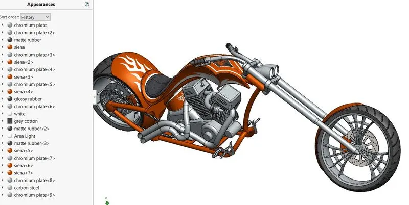
Fig158: Appearances (Colours and Materials)
Scene: The scene for rendering within Solidworks was chosen to be a plane white background.
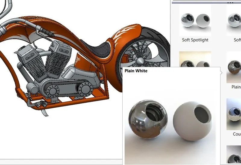
Fig159: Scene setup
Lights: No new lights were added for this project. The rendering was done using the default directional lights.
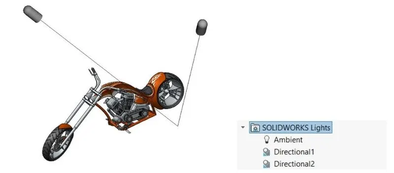
Fig160: Directional Lights
FINAL RENDERS
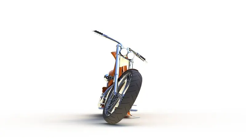
Front (Fig161)
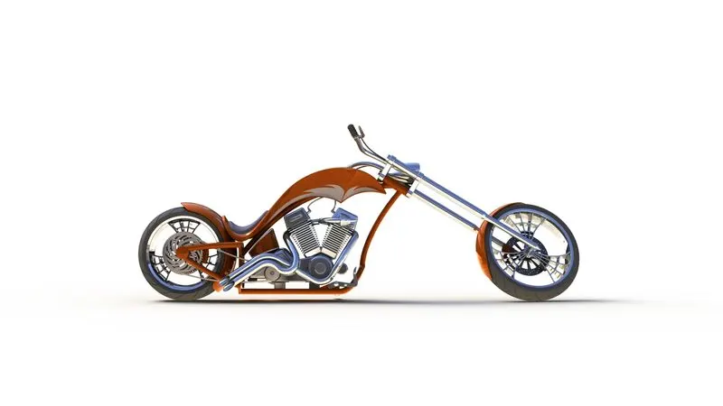
Side (Fig162)
Top (Fig163)
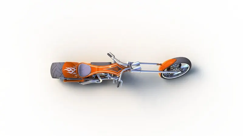
Isometric (Fig164)
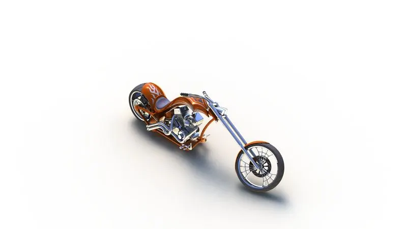
Camera Setup View (Fig165)
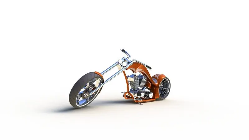
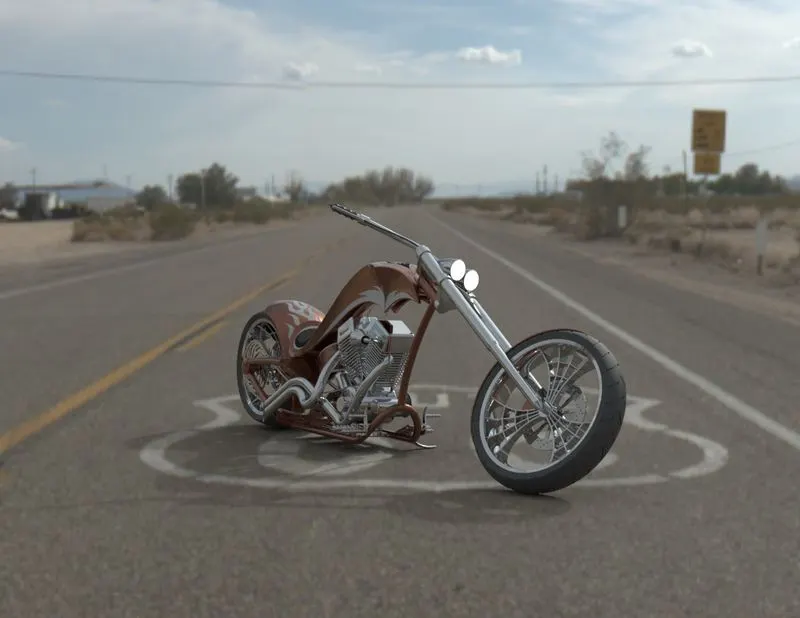
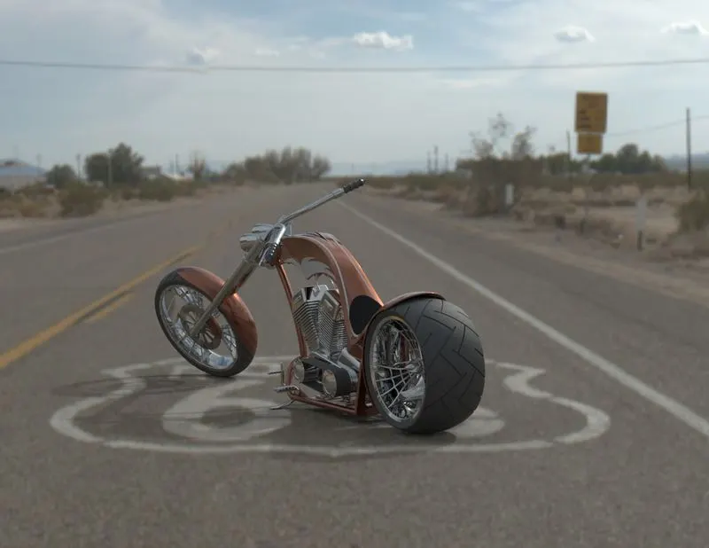
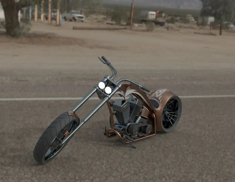
Solidworks Visualize Photorealistic Renderings
Conclusion
This project was successful in imparting the right knowledge in Solid Works modeling and has given a deep insight on both Assembly and rendering. A thorough examination of the steps followed will enable one to understand that this was a good starting point for anyone starting their career in design. I thank the support team at Skill Lync and my mentor Mr. Soundar Rajan for his continued support to successfuly complete this project.