Advanced Sheet Metal Design Using NX Cad Challenge_1_Casing Design
DESIGN OF SHEET METAL CASING USING NX CAD
OBJECTIVE
Modelling a casing using the sheet metal tools and features in NX CAD environment and creating a detailed drawing of the same.
INTRODUCTION
Software
Formerly known as Unigraphics, NX is an advanced CAD/CAM/CAE owned by Siemens PLM Software. It utilizes a parasolid geometric modeling kernel and is mostly used when advanced modeling features are required in a product. The ownership of the software belongs to the American Software company, Siemens (owned since 2007).
The NX 10 version has been used in this project.
Sheet metal
One of the fundamental forms used in metalworking, sheet metals are thin pieces which can be cut and bent into a variety of shapes. Thickness can vary from 0.5mm to 6mm. This process has been employed in this project to ensure a realistic approach in designing the part.
Target Model
The model chosen for this project is a sheet metal casing. Usually acting as an enclosure, a typical casing forms the outer layer of any component protecting it from external elements.
DESIGN METHODOLOGY
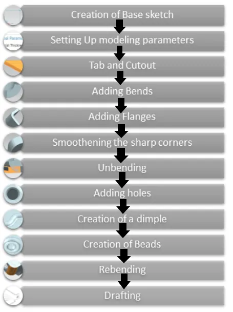
Process Flowchart
Features and Tools used
- Sketch: Rectangle, Line, Circle, Point,Move Curve, Studio Spline, Mirror Curve
- Sheet Metal(Basic): Tab
- Bend (SM*): Flange, Bend
- Corner (SM): Break Corner
- Punch (SM): Dimple, Bead
- Feature (SM): Normal Cutout, Hole, Mirror feature
- Form (SM): Unbend, Rebend
- Flat Pattern (SM)
- Drafting: Base View
[* - Sheet Metal]
DESIGN PROCESS
Units
This project has been done using Millimeters as the base unit.
Processes
(1) Creation of Base sketch
The base sketch was created on the XY plane. The rectangle tool was used to make the sketch and proper dimensions were added to fully constrain it. This provided the base for the tab feature which formed the next process in this project.
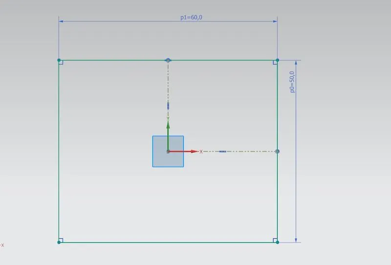
Fig1: Base sketch on XY plane
(2) Setting up modeling parameters
The preferences for the sheet metal operations were set up from the menu. This ensured a standard value for all the modeled components.
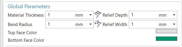
Fig2: Sheet Metal Preferences
(3) Tab and Cutout
The base solid was created using the Tab feature in under sheet metal application. It created a solid feature by extruding the base rectangular sketch along the Y-axis.
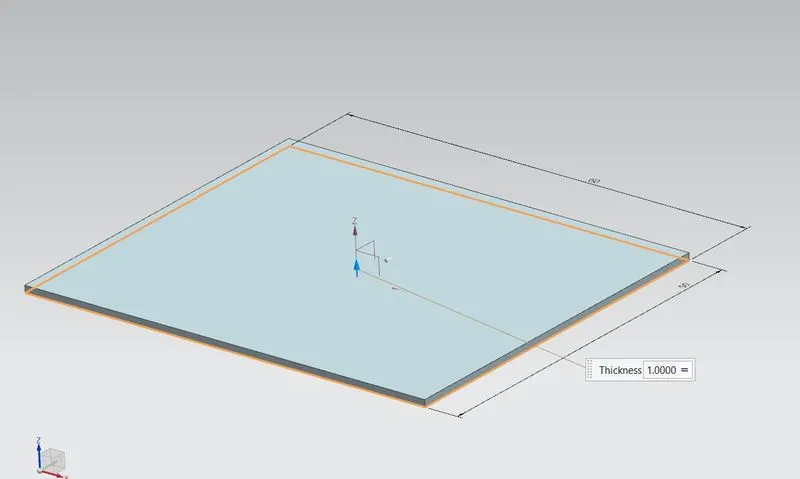
Fig3: Base Feature created using the Tab command
A rectangular cutout was then created on one edge of the base feature by using the Normal Cutout feature.
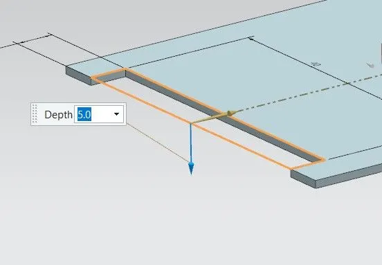
Fig4: Normal Cutout feature
(4) Bend
Using a line as the reference, the lateral edges were modified using the bend feature.
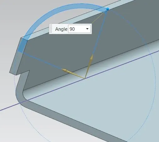
Fig5: Bend feature
(5) Flanges
Using proper edges as a reference, the corners of the bent faces were modified to include flanges. This was done using the Flange feature.
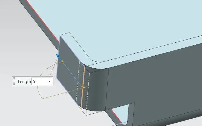
Fig6: Flanges
(6) Break Corners
The sharp corners which remained after the creation of solid features were smoothed using the Break Corners feature which rounded the sharp edges according to a proper radius value.
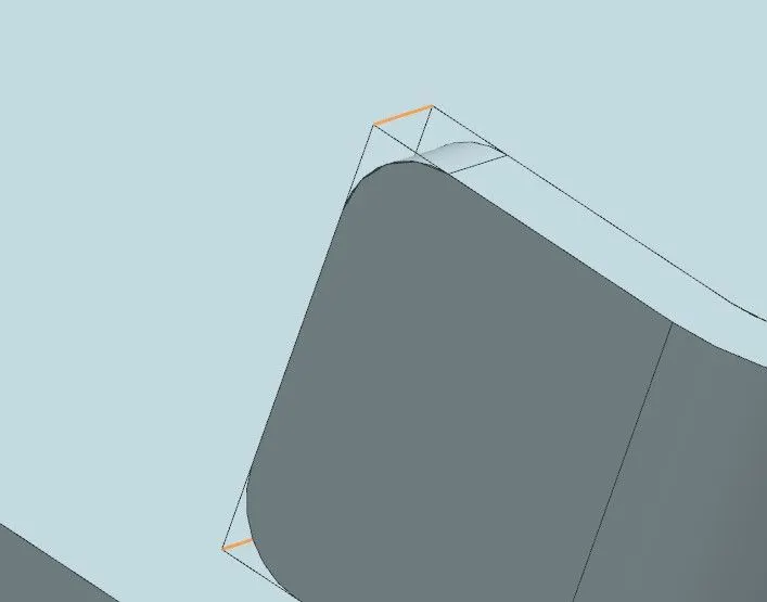
Fig7: Break Corners
(7) Unbend
For the creation of additional features like holes, the bent portions were straightened using the Unbend feature which was done by the systematic selection of the bent corners.
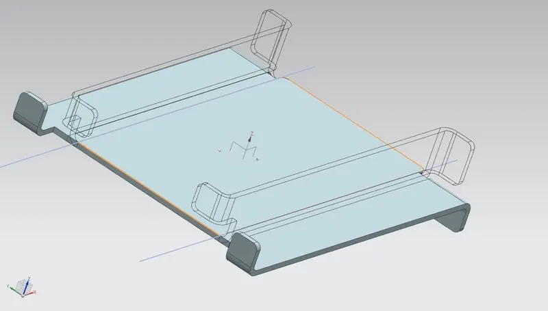
Fig8: Unbend feature (Lateral Edges)
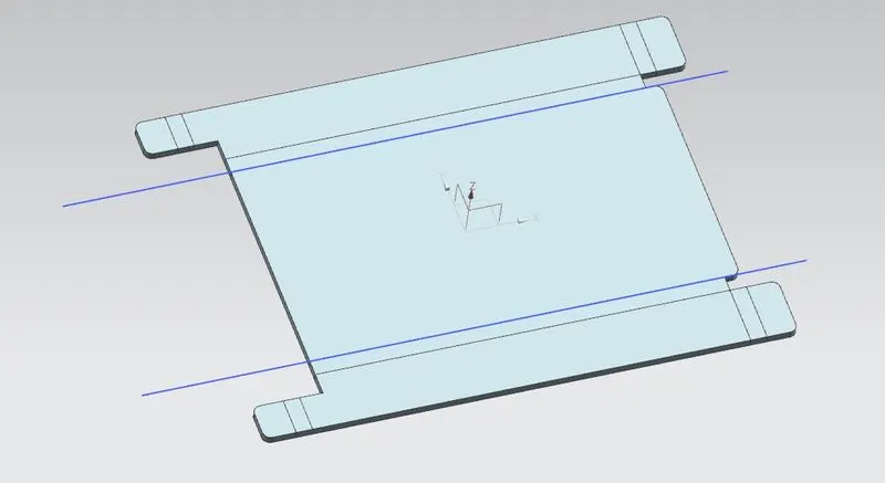
Fig9: Model after unbending
(8) Adding the Holes
Using a sketch on the XY plane, with addition of appropriate points on the unbent flanges, four screw holes were created using the Hole feature.
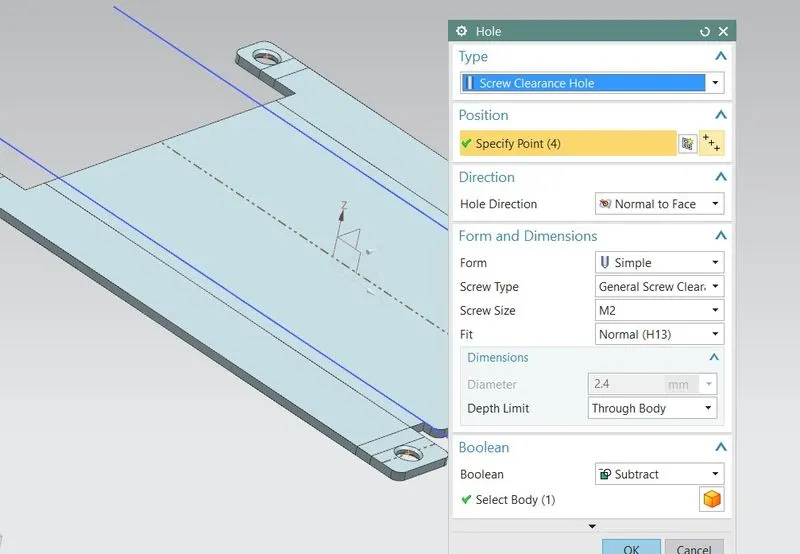
Fig10: Hole Feature
(9) Adding a Dimple
A depression was created using the Dimple feature which utilised the proper sketch to produce the result. The sketch consisted of a Studio Spline which was rotated about the centre to create the required shape.
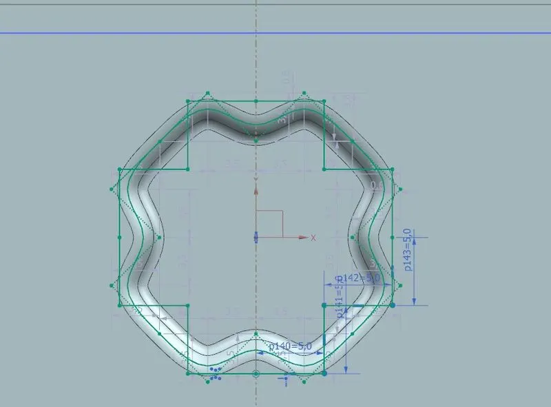
Fig11: Studio Spline (Sketch)
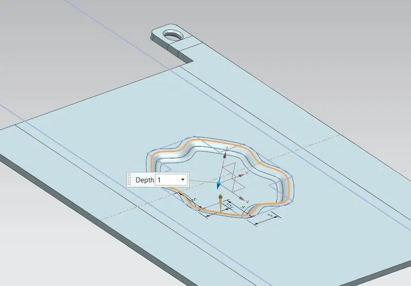
Fig12: Dimple Feature
(10) Adding Beads
Using a similar algorithm to that of a dimple, the bead feature creates a proper modification using a circle as the base sketch. Four beads are created in total, with the first one being mirrored about the proper plane to create the remaining.
Both the dimple and the bead are features under the Punch category in Sheet Metal and signifies a stamping process.
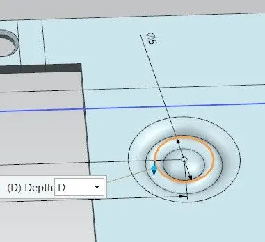
Fig13: Bead feature
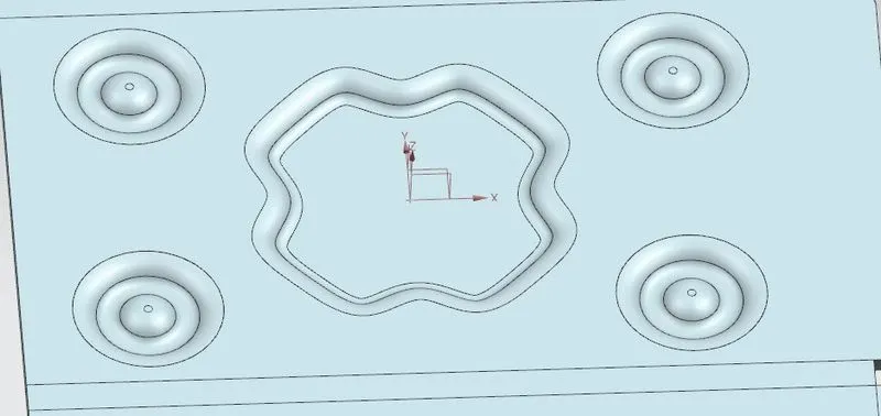
Fig14: Bead and Dimple features in the model
(11) Rebending
The final process consisted of reverting the model back to its original configuration by modifying the unbent edges using the Rebend feature. The path followed while unbending was repeated in a similar manner while rebending to ensure proper result.
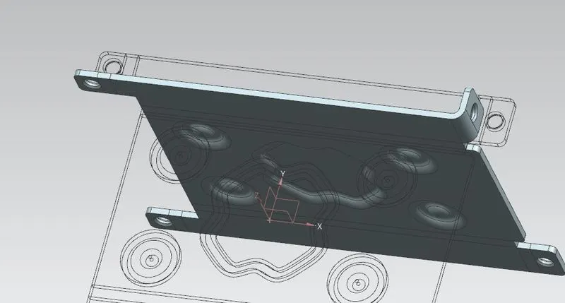
Fig15: Rebending feature
Standard Views
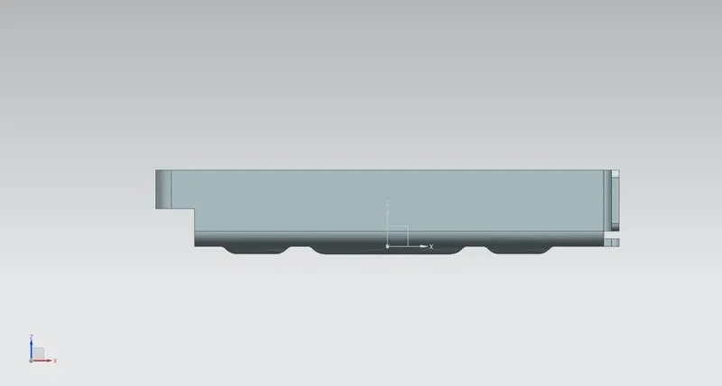
Fig16: Front View
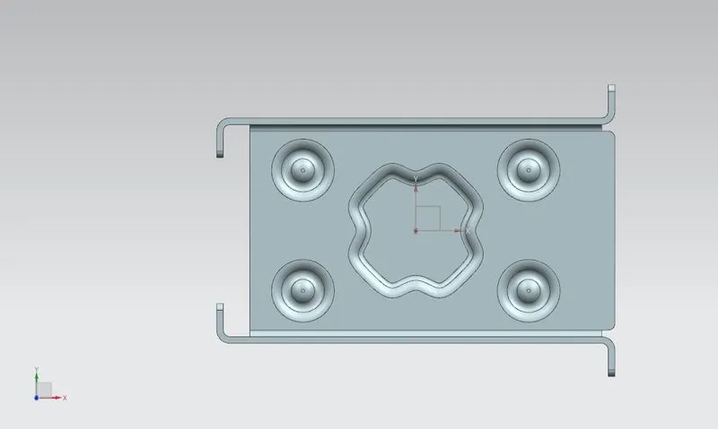
Fig17: Top View
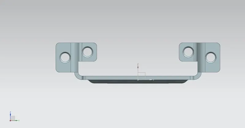
Fig18: Side View
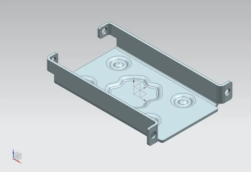
Fig19: Isometric View
(12) Drafting
To create a proper drawing for the model, the entire model was given a new view configuration using the Flat Pattern feature which removed all the bends and created a proper outline fit to be presented as a sheet metal drawing.
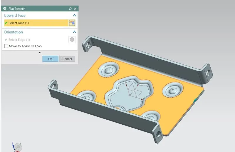
Fig20: Flat Pattern feature
The drawing or the draft was created using the drafting application which switched the part from sheet metal into a drafting environment. The sheet size was set as A4 and the view was set to the flat pattern view which was created before. The dimensions and other information were automatically added to the draft and the drawing was saved along the part.
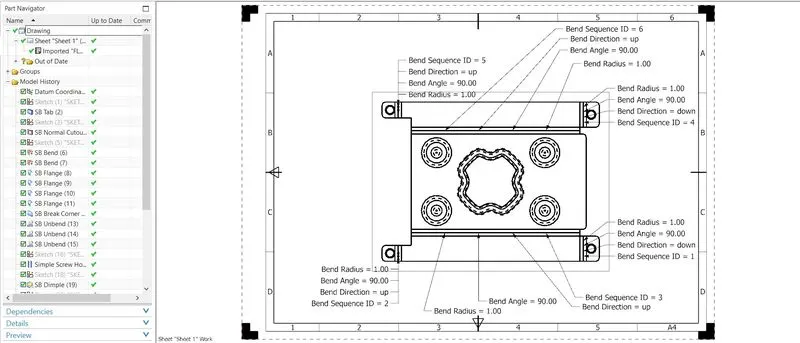
Fig21: Flat Pattern View Draft (A4)
Detailed drawing
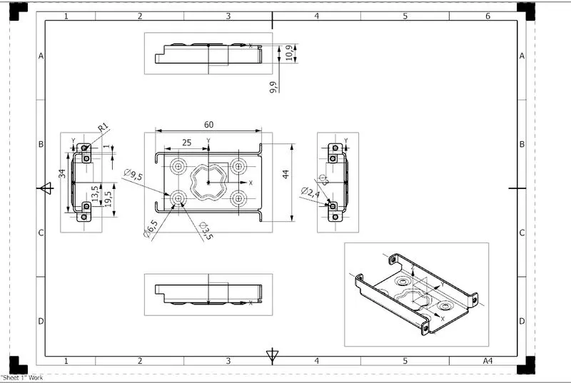
Fig22: Detailed drawing of the casing
CONCLUSION
The casing being a simple part, provided the best starting point for learning the various sheet metal modeling tools available in NX CAD. By following a systematic approach in the design process, the final product was modeled in a successful manner.