MODELLING AND ASSEMBLY OF A SUNSEEKER YACHT USING SOLIDWORKS
MODELLING AND ASSEMBLY OF A SUNSEEKER YACHT USING SOLIDWORKS
OBJECTIVE
To design the model of a Sunseeker Yacht using Solid Works by utilizing various part and assembly modelling techniques.
INTRODUCTION
SOLIDWORKS
Originally developed by an MIT graduate Jon Hirschtick in 1993 and later acquired by a French software corporation, Dassault Systemes SE (abbreviated 3DS), in 1997, Solid Works is a solid modelling computer -aided design (CAD) and computer -aided engineering (CAE) computer program.
It utilizes a parametric feature -based approach. This means that the model can be accessed from any angle since it is dimensioned in a completely 3-D environment. This, in turn, ensures two important principles in designing- repeatability and changeability.
The 2019 version of Solid Works has been used in this project.
SUNSEEKER YACHT
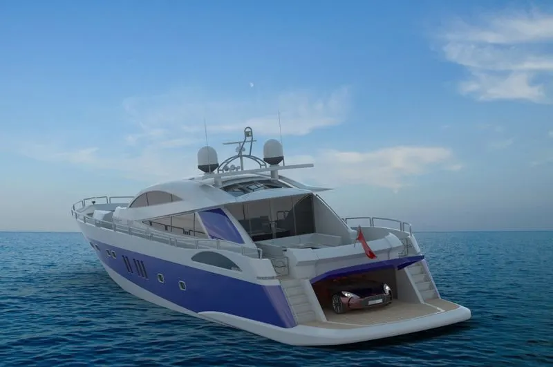
Sunseeker International is a brand of Luxury Motor Yachts headquartered in Poole, UK. The model used in this project is based on the Sunseeker Predator 108 (2008).
The project started off with the design of components such as propeller, seats etc. and then the entire model was assembled using the appropriate features in Solid Works. A proper appearance for the model was given to aid the rendering.
PROJECT OVERVIEW
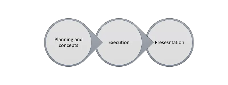
DESIGN METHODOLOGY
Design stages

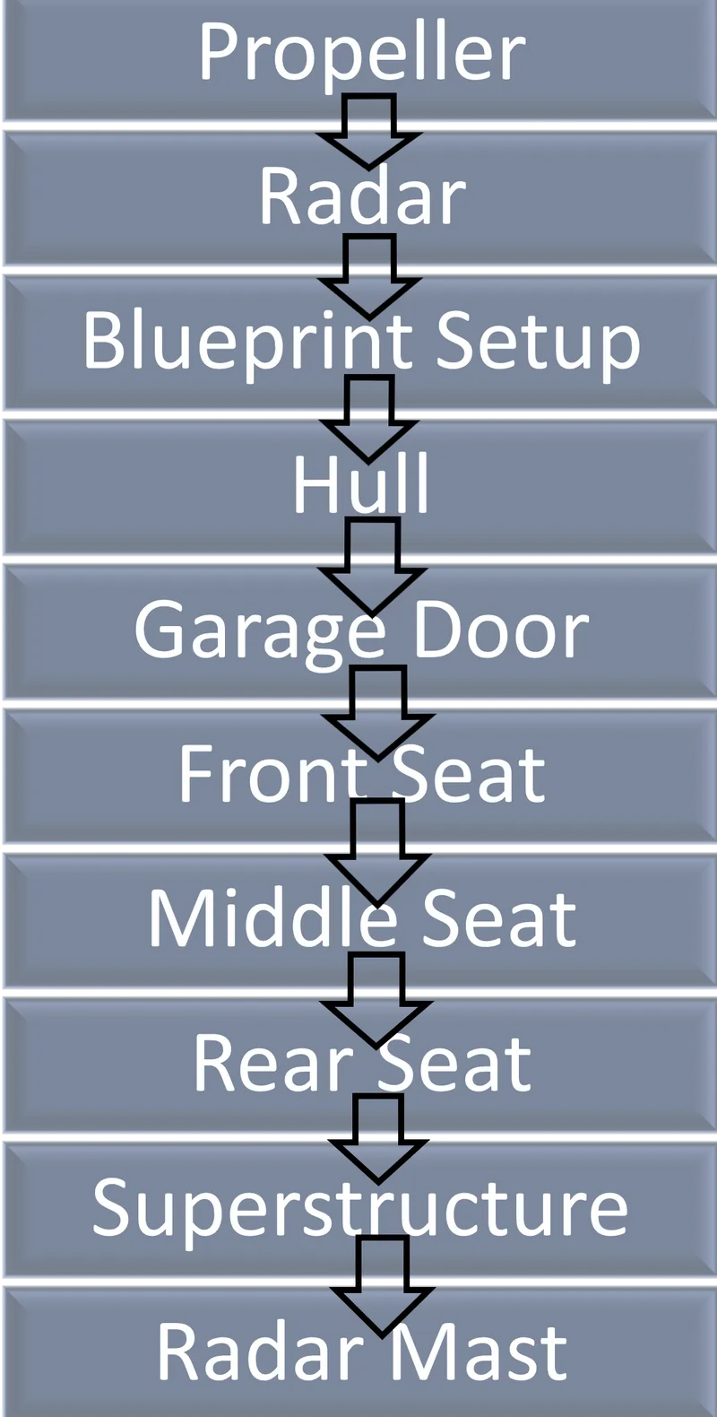
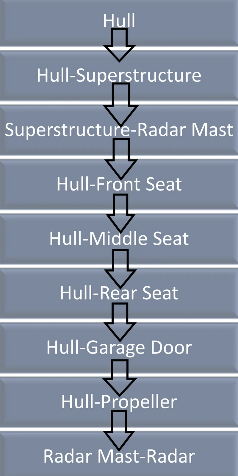
FEATURES AND TOOLS
SKETCH
The blueprint of the model which was used as a reference was imported to the sketch window using the sketch picture option among the sketch tools.
To create basic sketches the standard options such as line, arc, circle, spline etc. were used. Offset, convert and trim entities options were extensively used to create sketches from existing edges or sketches.
CURVE
The important tools used in this section includes projected curve, helix, and split line.
REFERENCE GEOMETRY
Reference planes were created to aid the modelling process.
SOLID
The following are the important solid modelling features used in this project:
- Boss/Base: extrude, revolve, sweep, loft
- Cut: extrude
- pattern or mirror: linear
- Other: fillet/round, chamfer, shell, combine, split, move or copy, delete or copy body, dome
SURFACE
The following are the important surface modelling tools used in this project:
- Sweep
- Trim
- Boundary surface
- Knit
- extrude
DESIGN PROCESS
UNITS
The mmgs unit system has been used in this project.
PART DESIGN
- PROPELLER
The propeller is a fan like structure which helps in propelling the Yacht using the power generated and transmitted by the main engine.
The propeller hub and cap, which forms the central components, were modeled using the Revolved Boss/Base feature, which takes a base sketch and revolves it around a central axis.
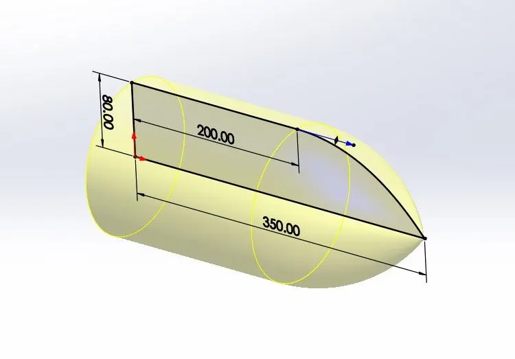 Fig1: Revolved Boss/Base
The propeller cap, which constitutes the front portion of the hub, was shaped using a spline in the sketch. Unlike a normal curve, a spline offers greater control over the curve by providing control handles which can be constrained using magnitude (weight) and direction (angle).
To model the blades, two rectangular sketches were made on two parallel planes. The second plane was created with reference to the top plane by using the Reference Plane feature and specifying an appropriate distance.
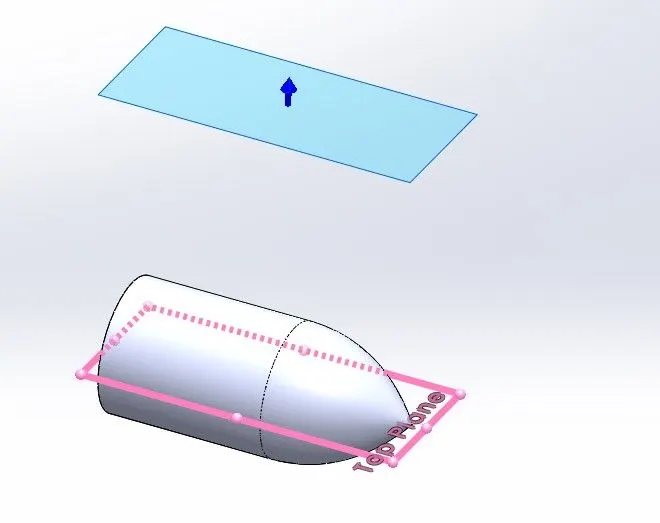 Fig2: Reference plane
The two sketches were then used to create the blade with the aid of Lofted Boss/Base feature which adds material between two or more profiles to create a solid body.
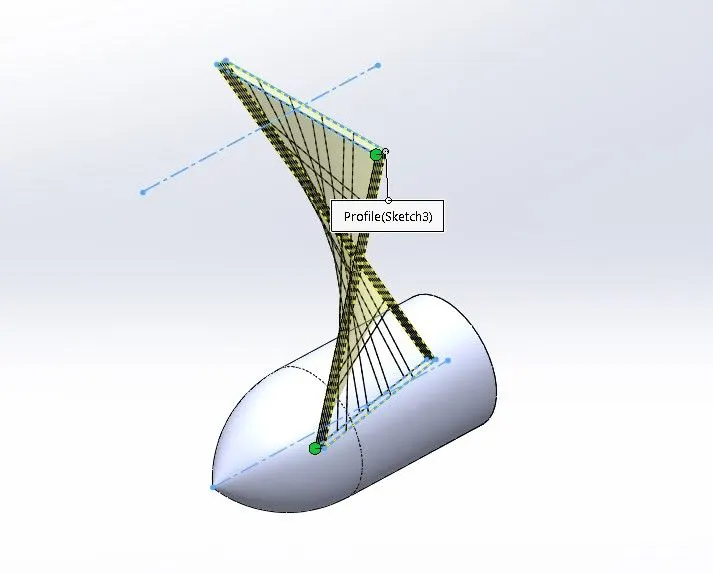 Fig3: Lofted Boss/Base
The sharp corners on the blade tip were smoothened using the Fillet/Round feature.
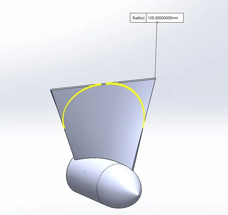 Fig4: Fillet/Round
A cylindrical cavity was then created on the rear side of the hub (provision for the shaft) using the Cut-Extrude feature, which uses a sketch to remove material from a solid body.
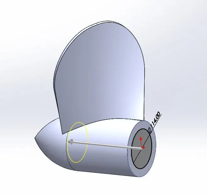 Fig5: Cut-Extrude
The remaining sharp edges which included the leading and trailing edges, and the root were filleted to make the design smoother. Using the hub as a reference, the blade was then patterned using the Circular Pattern feature to complete the propeller model.
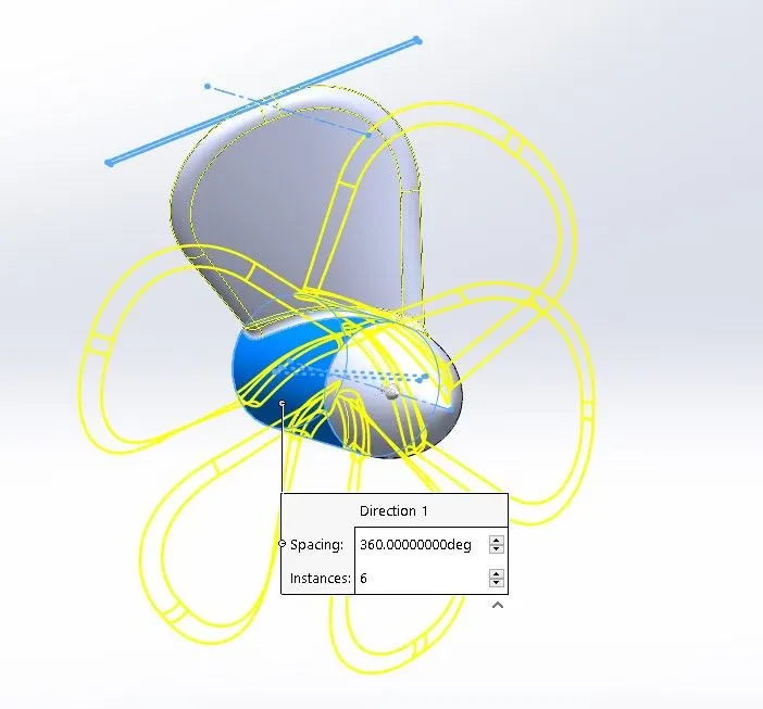 Fig6: Circular Pattern
A custom brown appearance was given to this part.
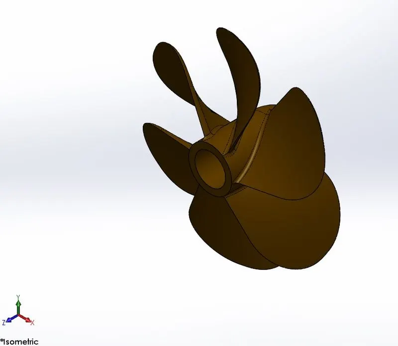 Fig7: Propeller (isometric View)
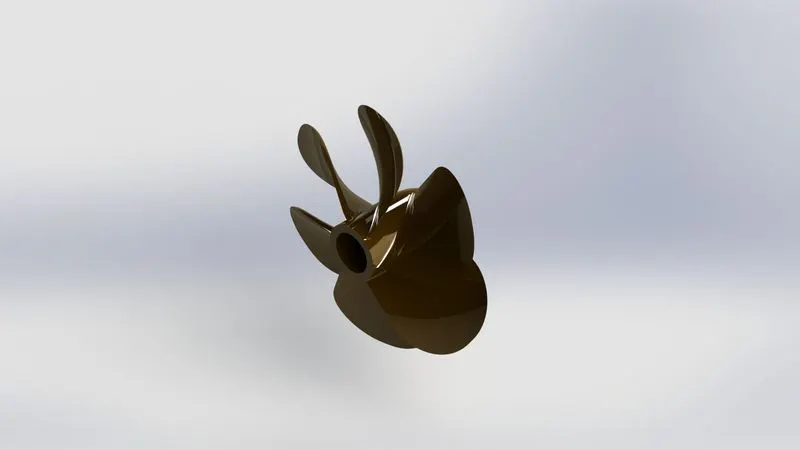 Fig8: Final Render
- RADAR
Marine radars are used to detect other water vessels or obstacles during sailing. The radar used on this model is a rotating X band version.
The body of the radar was designed by using Extrude Boss/Base feature to create a solid body from a sketch.
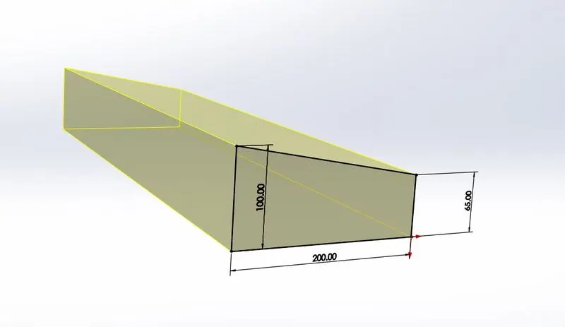 Fig9: Extrude Boss/Base
The solid features which were created on the left end of the radar, was patterned using a Sketch Driven Pattern feature. The patterned features were located correctly using sketch points.
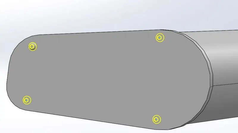 Fig10: Sketch Driven Pattern
The model was then mirrored about the right plane using the Mirror feature. Using appropriate options such as the Merge solids and Knit Surfaces, the entire body was modelled into a single solid body.
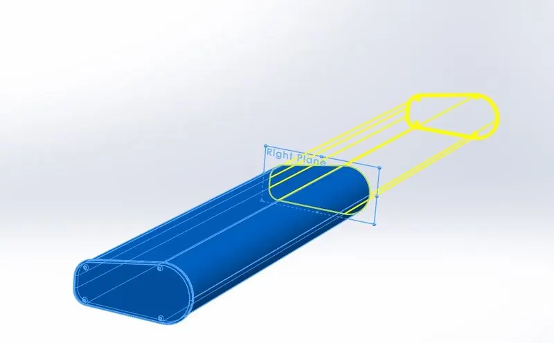 Fig11: Mirror
A text was projected on to the radar surface by using the Split feature which made use of an existing sketch (Text option in sketch).
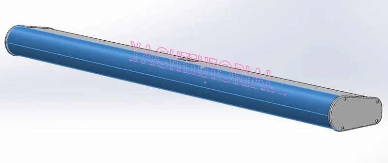 Fig12: Split
A white appearance was given for this part. The text was given a custom dark grey appearance.
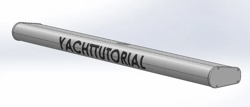 Fig13: Radar
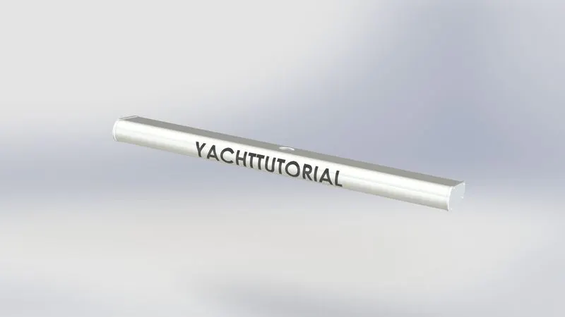 Fig14: Final Render
- BLUEPRINT SETUP
Blueprints, which are basically orthogonal drawings of the desired product, helps provide the foundation for starting any sketch.
The Sketch Picture tool was used to import the necessary blueprints of the model on to the respective planes. Appropriate dimensions and names were given to the blueprints for proper reference during the modelling. Some of the existing planes were renamed and new planes were also created using the Reference geometry feature to accommodate all the blueprints.
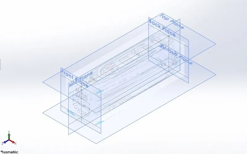 Fig15: Blueprint Setup (Isometric view)
- HULL
A hull is the watertight body of a ship or a boat, which is covered by a deck on the top, which houses a superstructure and other similar features.
Being the base of every other feature in this model, the hull design had a lot of features the majority of which were modelled using the surface modelling tools.
The projected curve feature was used to create the surfaces that made up the outer surface of the hull. This tool helped create a curve which appears at the intersection of two perpendicular sketch planes.
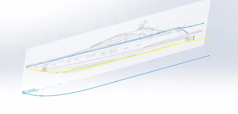 Fig16: Projected Curve
Once the necessary curves were created, the surface was designed using the surface loft feature, which creates a lofted surface between two or more profiles based on guide curves.
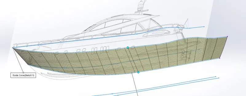 Fig17: Surface Loft
The unwanted portions of the lofted surface were then removed using the surface trim feature, which makes use of a sketch or an edge to trim a surface.
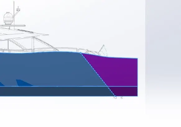 Fig18: Surface Trim
To create the swim platform, the desired shape was created using a sketch and the surface was then extruded using the surface extrude feature.
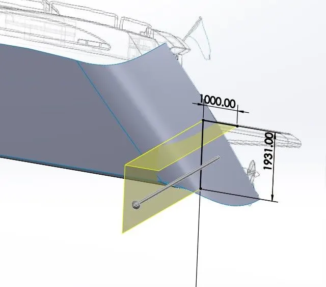 Fig19: Surface Extrude
The created surfaces were then joined together using the surface knit feature. Once the knit is proper the boundary edges could be identified by dark lines while the disjoint edges remained blue.
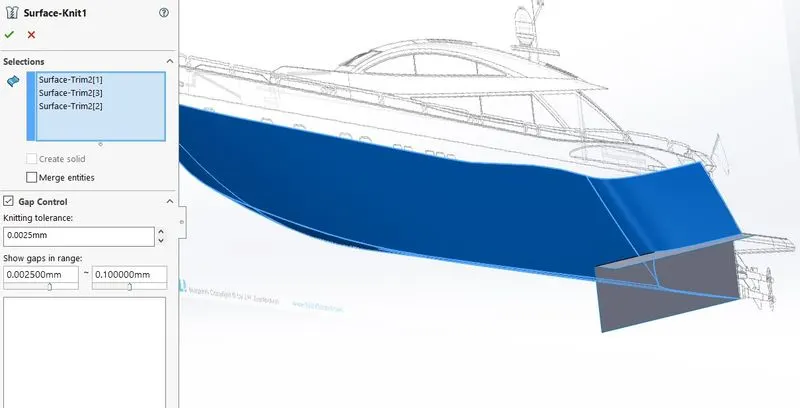 Fig20: Surface Knit
To remove the excess portion in the surface used to create the swim platform, the surface trim feature was used with the help of an existing surface as the reference.
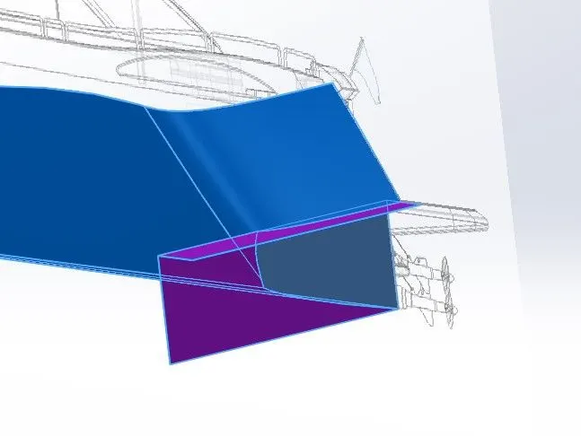 Fig21: Surface Trim
To create a surface at the symmetric plane and close the model, the surface fill feature was used which makes use of multiple edges to create a surface between them. This tool additionally made the entire surface body into a solid body which became the base for the deck modelling.
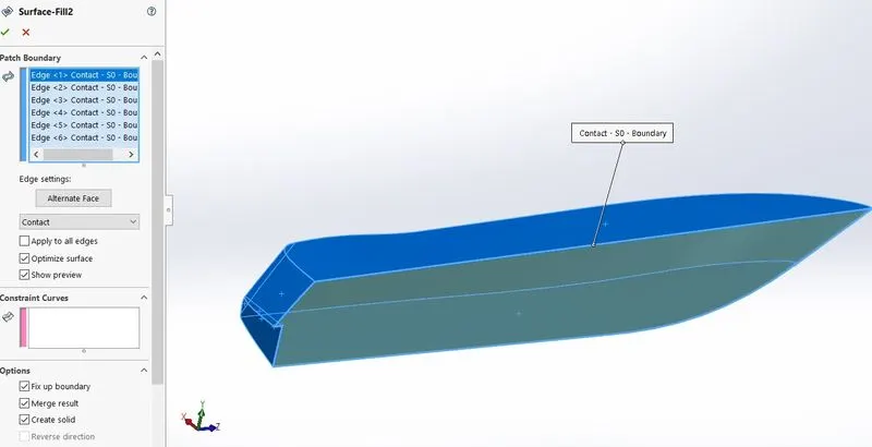 Fig22: Surface Fill
For the solid to be converted into a hollow thin-walled feature, the shell feature was used.
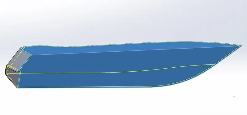 Fig23: Shell
The deck surface was then created using the boss/base extrude feature.
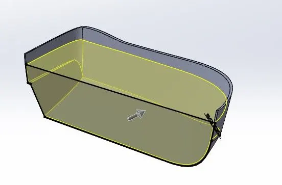 Fig24: Boss/Base Extrude
To make room for the stern, the rear end was trimmed away using the cut extrude feature.
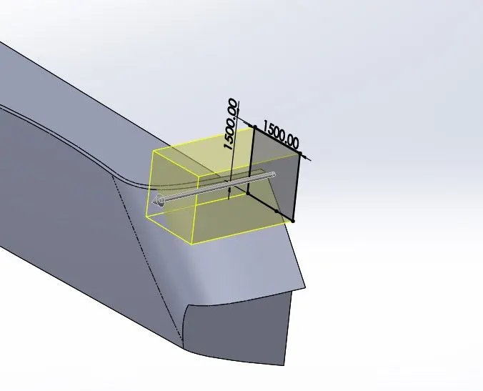 Fig25: Cut Extrude
Sharp edges resulting from extrusion were smoothened and rounded off using the fillet/round feature with appropriate radius values.
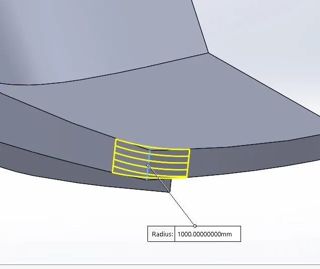 Fig26: Fillet/Round
Similarly, to create an angular appearance to outer edges, the chamfer feature was also used.
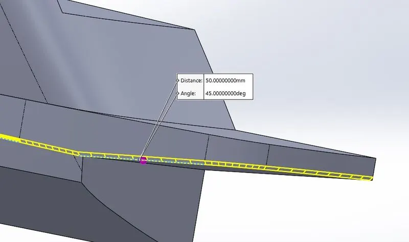 Fig27: Chamfer
The windows were created using the cut extrude feature but instead of a blind parameter, an offset from surface option was chosen to correctly remove material from the nonlinear surface of the hull.
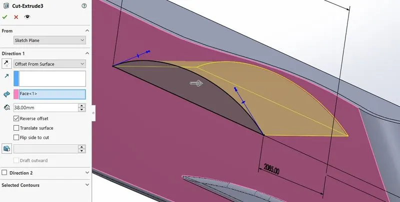 Fig28: Cut Extrude (Offset from surface)
To create the frame for the windows on the side of the yacht, the sweep feature was used which created a solid feature based on a predetermined profile and path.
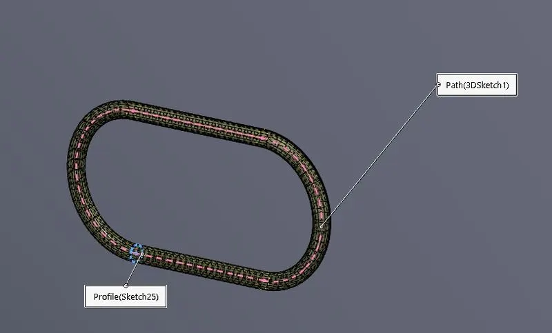 Fig29: Sweep
To create the cylindrical parts for the windlass situated in the bow of the yacht, the revolved boss/base feature was used, which takes a sketch and revolves it around a central axis.
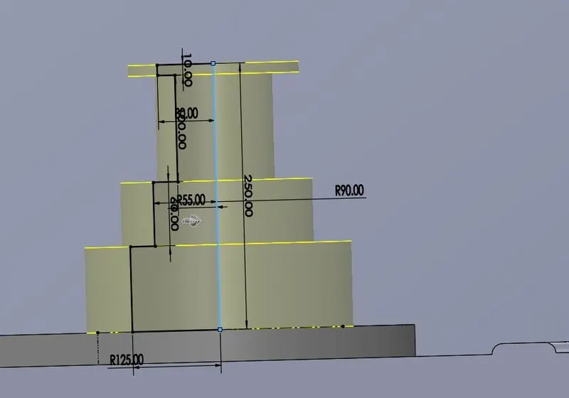 Fig30: Revolve boss/base
The circular face of the topmost cylinder in the windlass was given a curvy appearance using the dome feature.
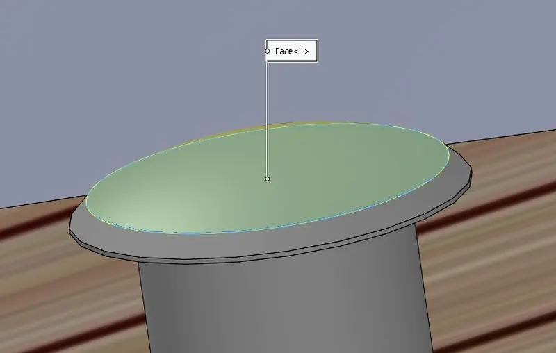 Fig31: Dome
To model the anchor chain wound around the drum of the windlass, the helix feature was used while creating the sketch, with the appropriate pitch and number of revolutions.
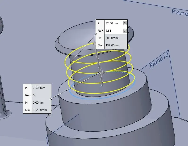 Fig31: Helix
The linear pattern feature was used to create similar features present in the deck with reference to an existing feature.
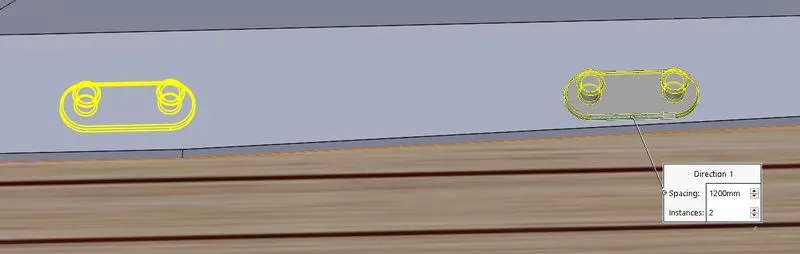 Fig32: Linear Pattern
The railing present in the gunwale of the yacht was modelled using a series of curves whose dimensions were approximated based on the blueprints and then made into a solid using the sweep feature.
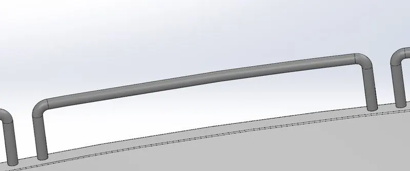 Fig33: Railings
Any protruding portion of the railings were removed from the hull body using the delete body/face feature.
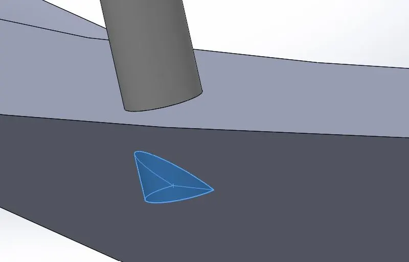 Fig34: Delete body/face
The garage towards the stern of the yacht was created using cut extrude feature and the front portion of the garage was exported as a separate part to model the garage door.
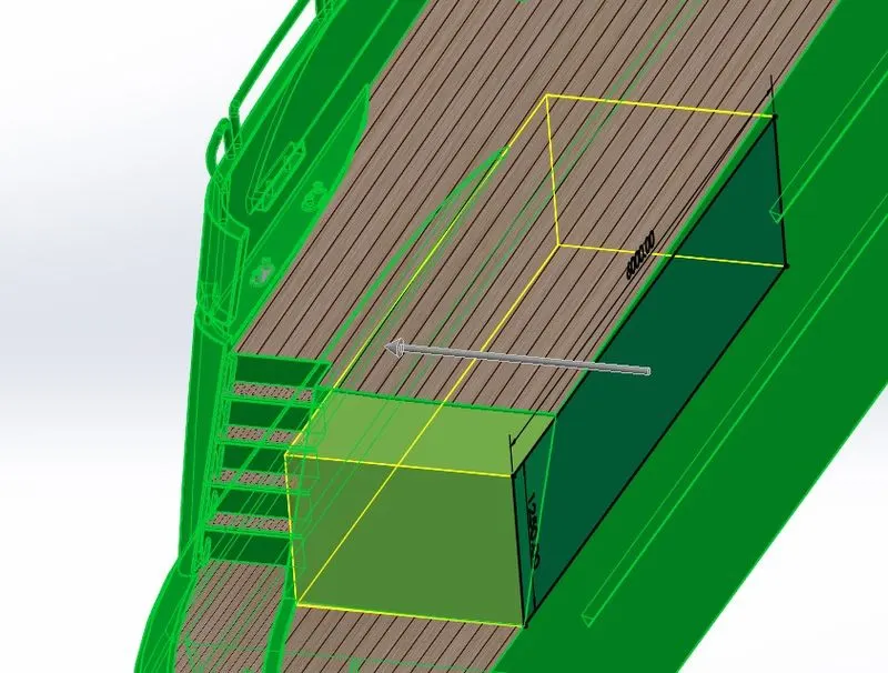 Fig35: Cut Extrude (Garage)
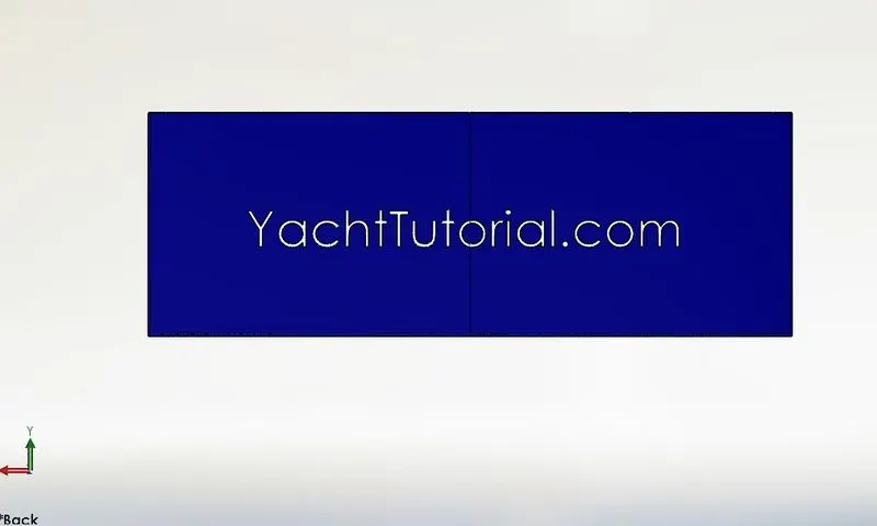 Fig36: Garage Door
Other parts associated with the hull such as the stairs, the propeller shafts etc. were also modelled using a combination of the above-mentioned features. The entire model was then mirrored about the mid plane to create the hull.
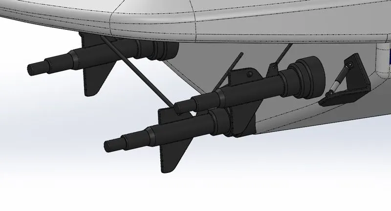 Fig37: Propeller Shafts
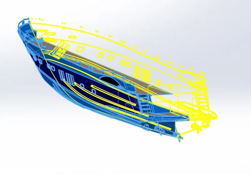 Fig38: Mirror
Proper appearance was then given to different parts of the hull. To create a shade of a different colour on the side of the hull, the split line feature was used. This enabled to select a face from the middle portion of the hull surface since the line was projected on to the specified surface to create a boundary.
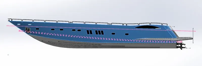 Fig39: Split line
A zero offset surface was also created using the surface offset feature to provide a reference for components which needed to be assembled to the deck of the yacht.
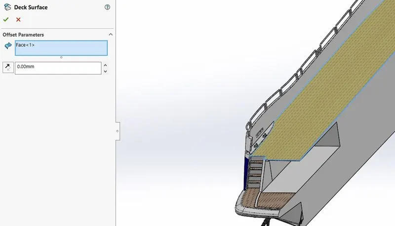 Fig40: Surface Offset
Decals were applied to the deck surface and the stairs to make the model realistic while rendering.
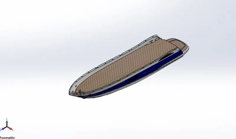 Fig41: Hull (isometric)
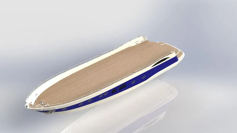 Fig42: Hull (Render)
- SEATS
While designing the seats, the deck surface was chosen as the reference and to import the surface into the design window, the insert part feature was chosen. From the bodies which could be chosen the offset surface created above the deck was chosen.
Using the before mentioned surface and solid modelling features, the seats along with the appropriate structure was modelled for three portions of the yacht: front, middle and rear. Appropriate appearances were given to each part.
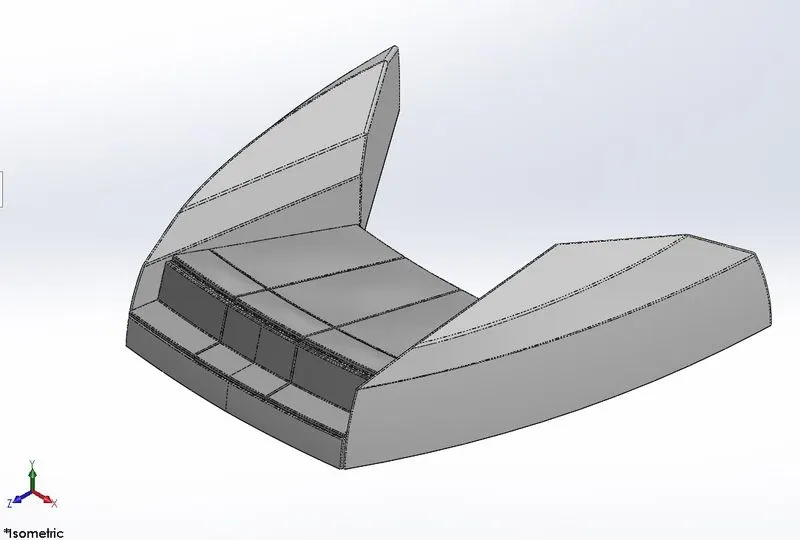 Fig43: Front Seat
 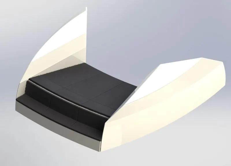 Fig44: Front Seat (Render)
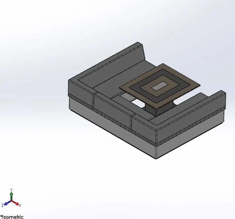 Fig45: Middle Seat
 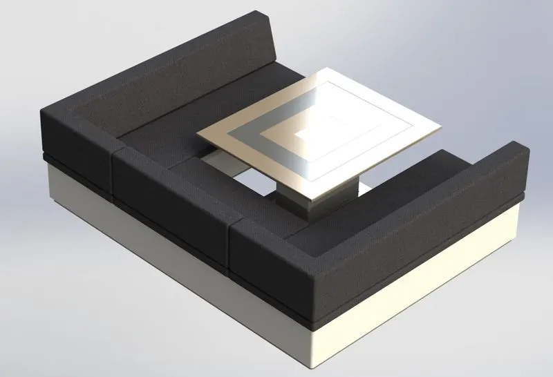 Fig46: Middle Seat (Render)
The ruled surface feature was used to create a surface tangent to an existing surface while modelling the rear seat.
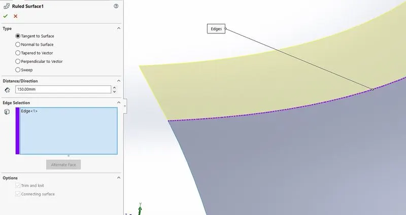 Fig47:Ruled Surface
An approximated 3D sketch-based surface loft was used to model the flag situated behind the rear seat.
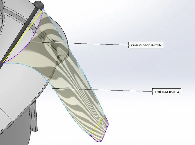 Fig48: Surface Loft
The gates for the entry into the swim platform through the stairs was modelled along with the rear seat.
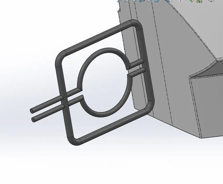 Fig49: Gate
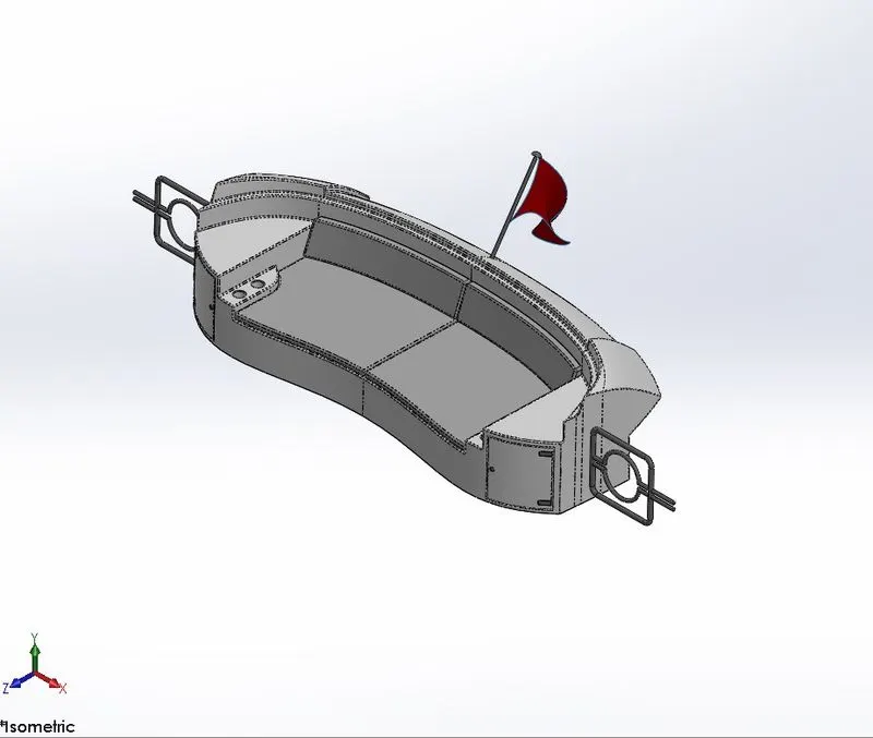 Fig50: Rear Seat
 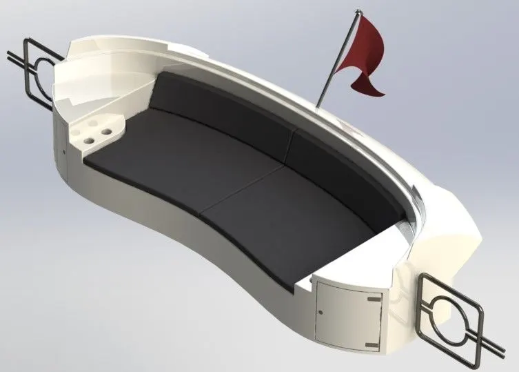 Fig51: Rear Seat (Render)
- SUPERSTRUCTURE
The part of the yacht which projects above the deck surface is termed as a superstructure. It houses the space for passengers and goods.
The outer body of the superstructure was modelled using various surface modelling features. All adjoining surfaces were knitted using the surface knit feature to avoid errors during mirroring.
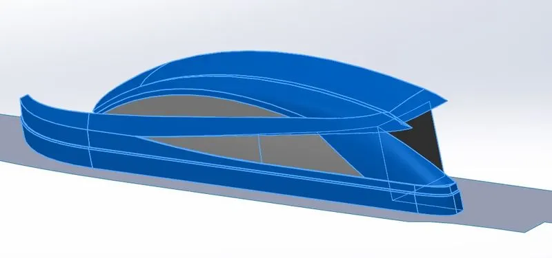 Fig52: Surface Knit
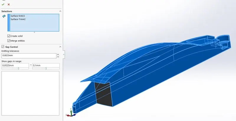 Fig53: Knitting and converting to solid
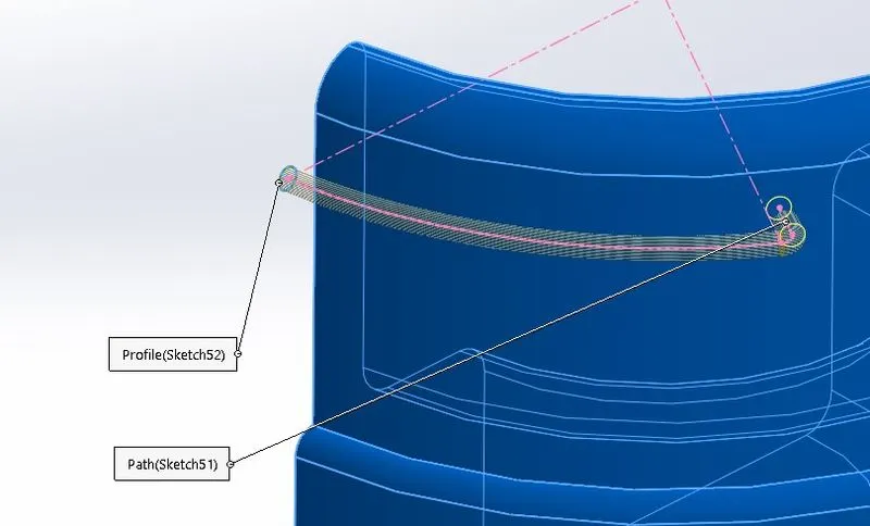 Fig54: Sweep (railings)
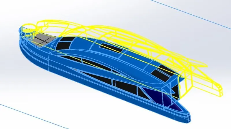 Fig55: Mirror
More focus was given to detail the superstructure to make it more realistic. Some of these details include extrusion and removal of material to create the windows, adding 3d sketches to create wipers for the front window, using a combination of solid and surface features to create a jacuzzi along with seats towards the front area. Appropriate appearances were given to the components of the superstructure and decals were added to the jacuzzi stairs.
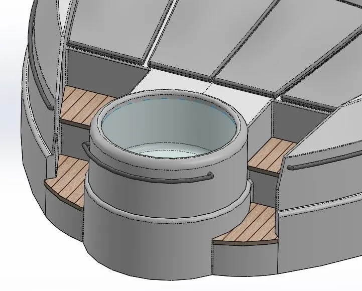 Fig56: Jacuzzi and stairs
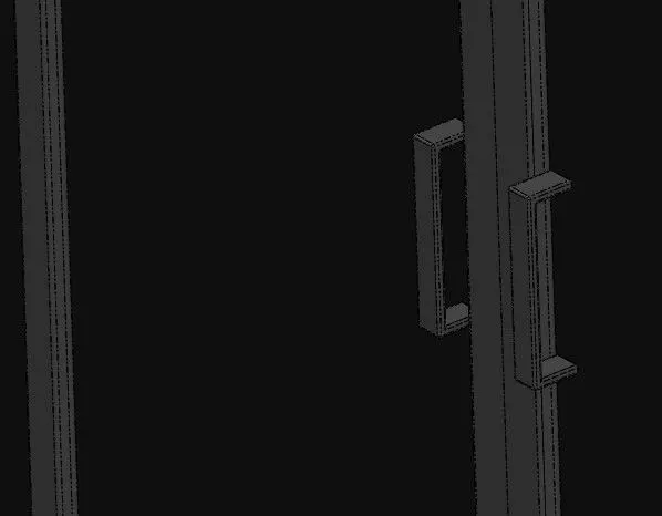 Fig57: Door Handles (extrude thin feature)
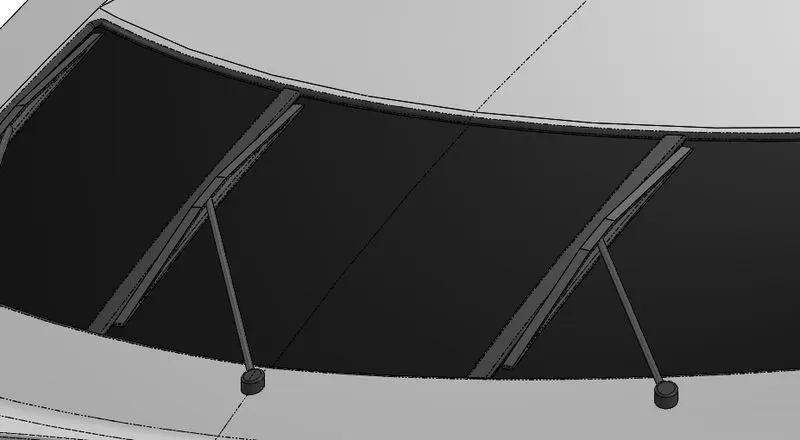 Fig58: Wipers
Proper references for the addition of a radar mast were provided on the top rear end of the superstructure roof using the surface offset feature to create a zero-offset surface.
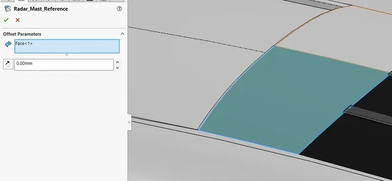 Fig59: Surface offset (Radar mast reference)
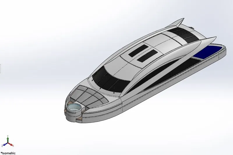 Fig60: Superstructure
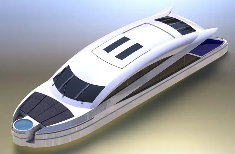 Fig61: Superstructure (Render)
- RADAR MAST
The reference was setup by importing the surfaces from the superstructure part.
The base was created using a boss/base extrude feature and the light bulbs and antenna were created using revolved boss/base feature.
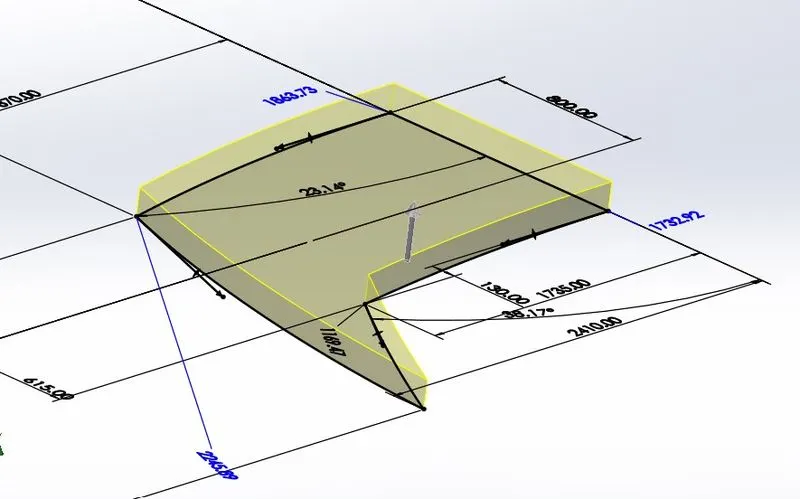 Fig62: Boss/base Extrude
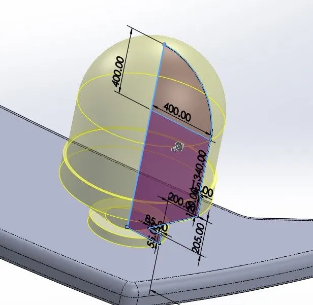 Fig63: Revolve Boss/base
The frame in the middle was created using the sweep feature and fog horns were modelled using the revolve feature and made hollow using the shell feature.
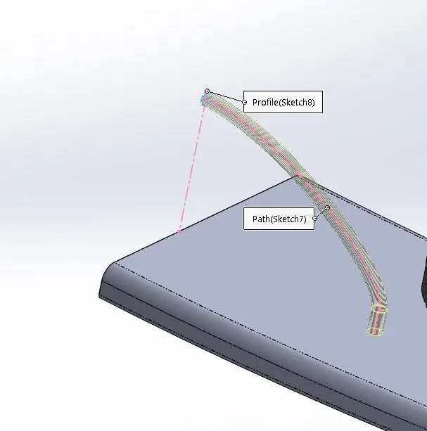 Fig64: Sweep
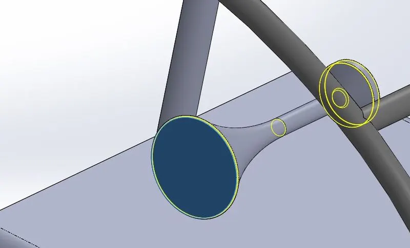 Fig65: Shell
The entire model is then mirrored about the mid plan to create the radar mast.
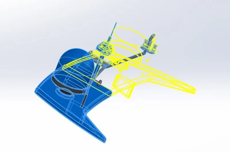 Fig66: Mirror
Appropriate appearances were also given to different parts.
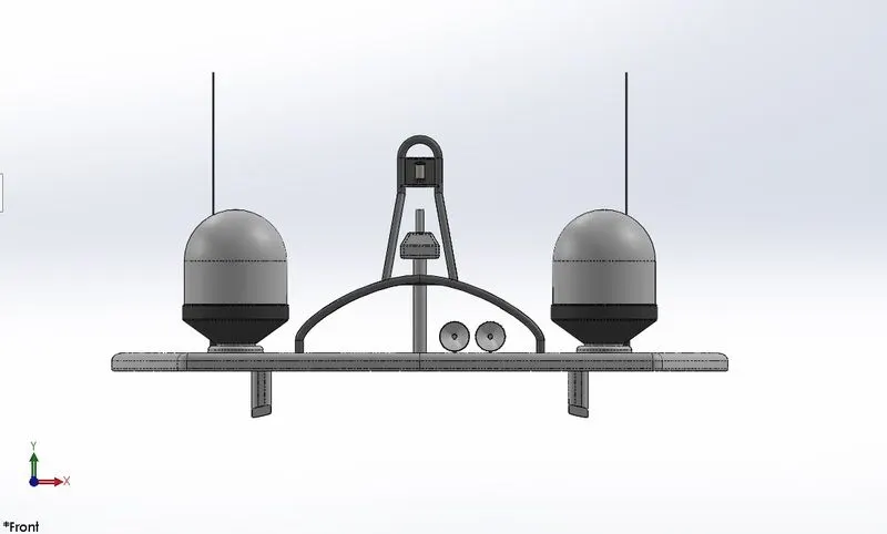 Fig67: Radar Mast (Front View)
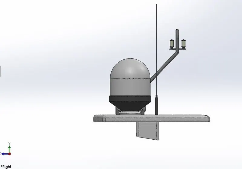 Fig68: Radar Mast (Side View)
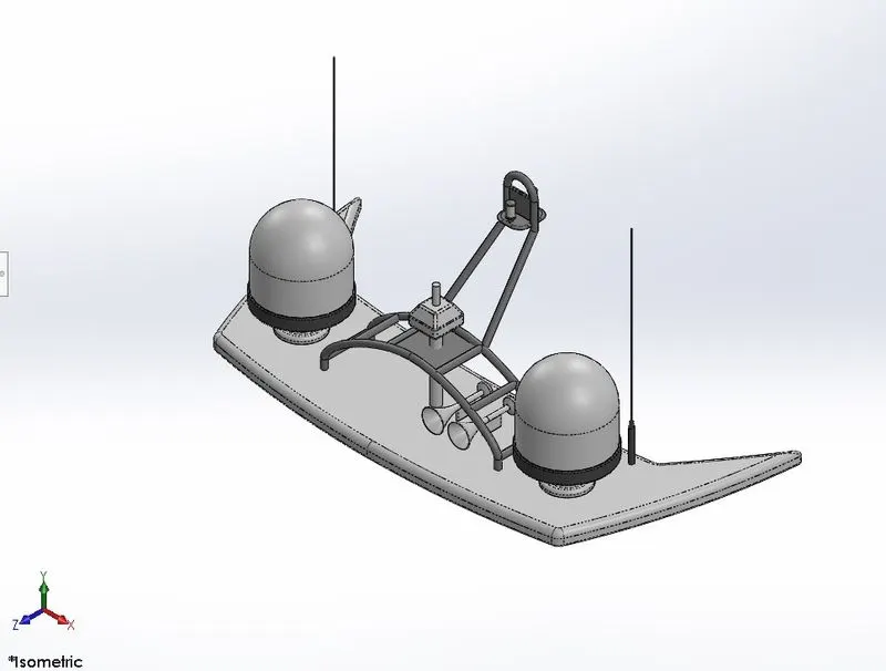 Fig69: Radar Mast (Isometric View)
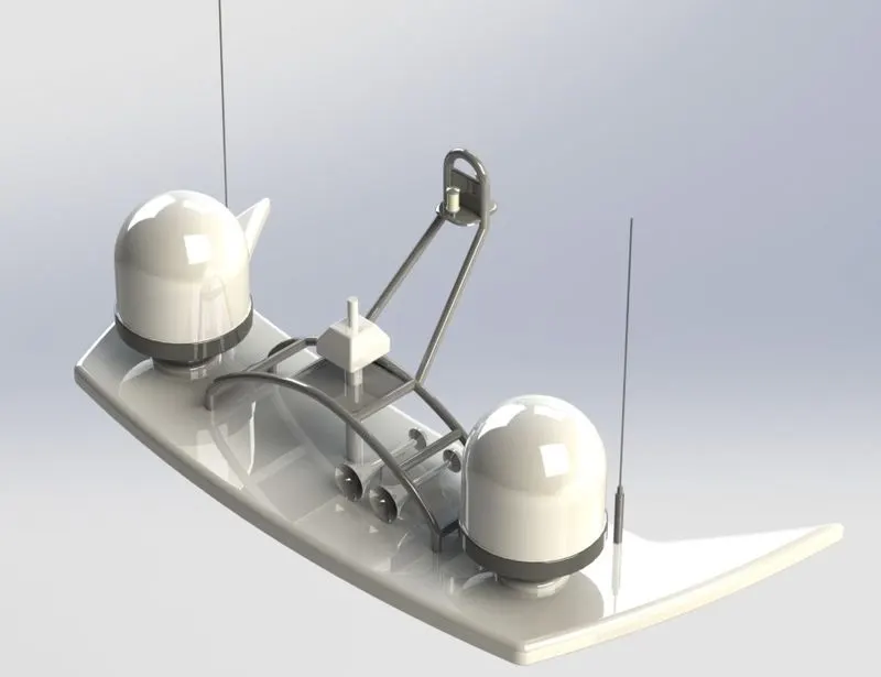 Fig70: Radar Mast (Render)
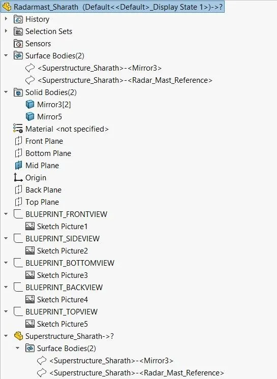
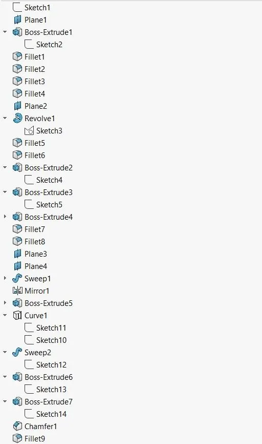
Feature tree for radar mast:
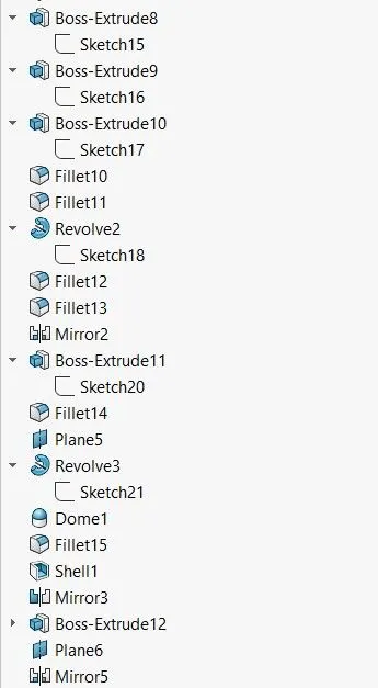
ASSEMBLY
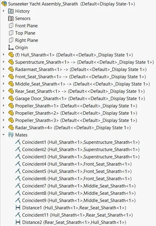
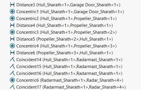
An assembly is a combination of parts or components that has a specified relation to each other. This relation is termed as a Mate. Two mating parts in Solidworks can have various mating relations based on user specifications and geometry.
The following are the types of mates used in this project:
- Coincident: The mating parts are coincident with each other based on the coincidence of a surface or a sketch plane.
- Concentric: The mating parts having spherical surfaces are mated to the same centre point.
- Distance: The mating parts are separated by a specified linear distance.
- Hull: The hull was the first part to be imported into the assembly window after setting the correct units.
- Hull-Superstructure: The Superstructure was assembled to the hull by aligning the sketch planes using a coincident mate.
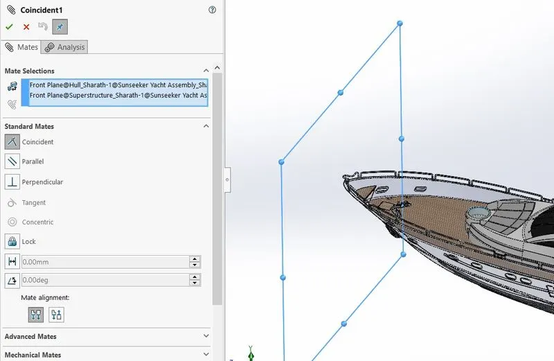 Fig71: Coincident Mate (Superstrucure)
- Hull-Radar Mast: The radar mast was correctly aligned to the superstructure by using the same coincident mate relation between the sketch planes of the hull or superstructure.
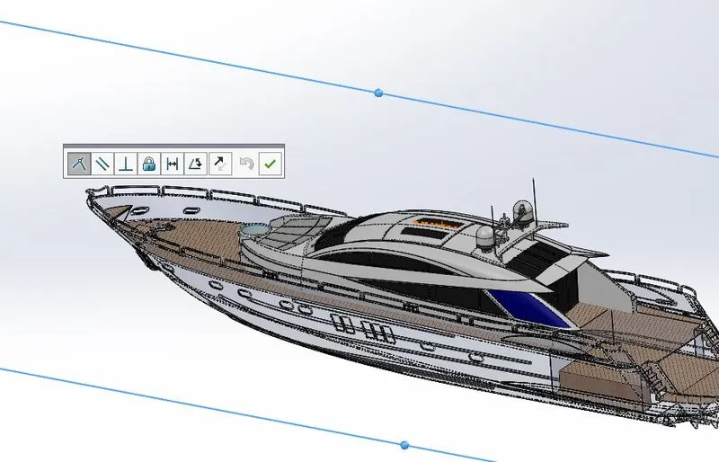 Fig72: Coincident Mate (Radar Mast)
- Hull-Seats: The front and middle seats were mated to the deck using coincident mates. The rear seat was assembled to the deck using a coincident mate between the mid planes and two distance mates to position it correctly.
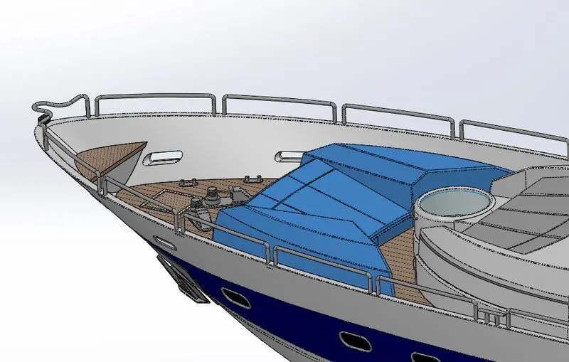 Fig73:Front Seat Assembly
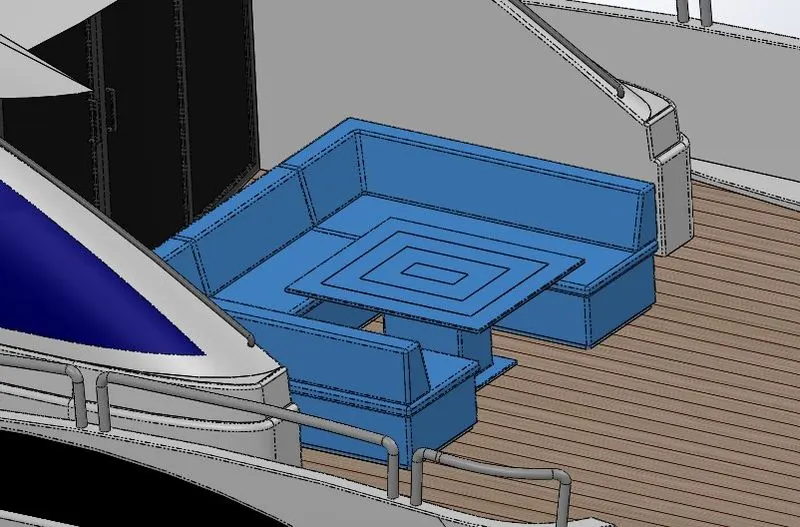 Fig74: Middle Seat Assembly
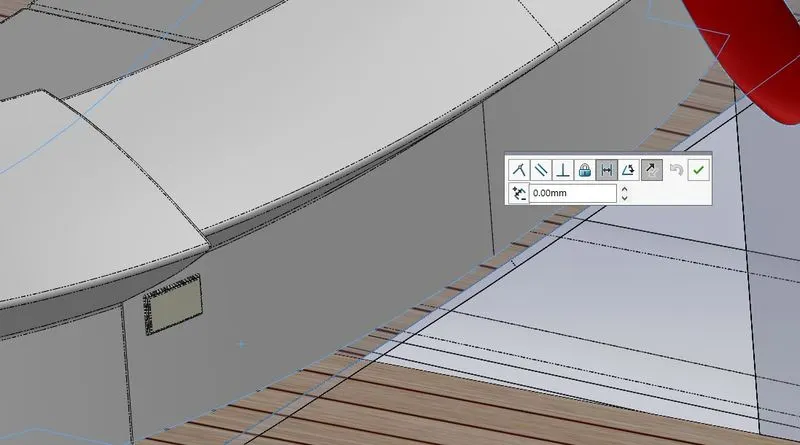 Fig75: Distance mate (Rear Seat- Y position)
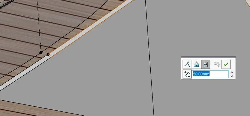 Fig76: Distance Mate (Rear Seat- Z position)
- Hull-Garage Door: The garage door was positioned first using a Coincident mate between the mid planes and then fully defined using a Concentric mate at the hinges. The lock rotation option was used to make the assembly fully defined. To position the door at different angles to simulate its realistic operation the option could be toggled to aid the presentation.
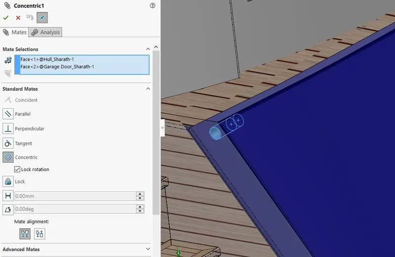 Fig77: Concentric Mate (Garage Door)
- Hull-Propeller: The propeller was assembled using a Distance mate to specify the Z axis position and a Concentric mate to make it fully defined. This was repeated for the assembly of three propellers.
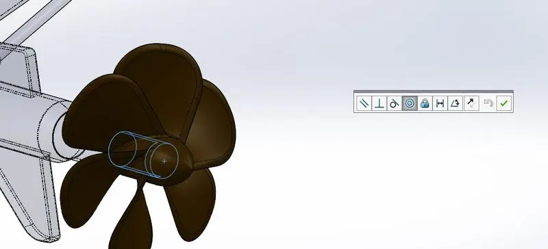 Fig78: Concentreic Mate (Propeller)
- Radar Mast- Radar: The radar was mated to the shaft in the radar mast using a combination of Concentric and Coincident mates.
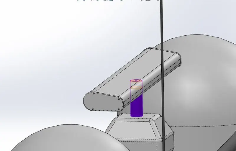 Fig79: Radar assembled to the Radar Mast
ASSEMBLY- Standard Views
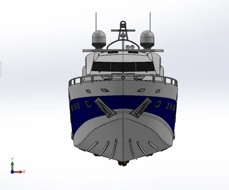 Fig80: Front
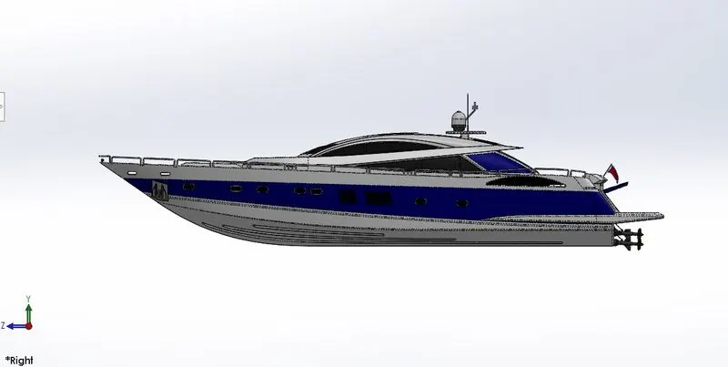 Fig82: Side
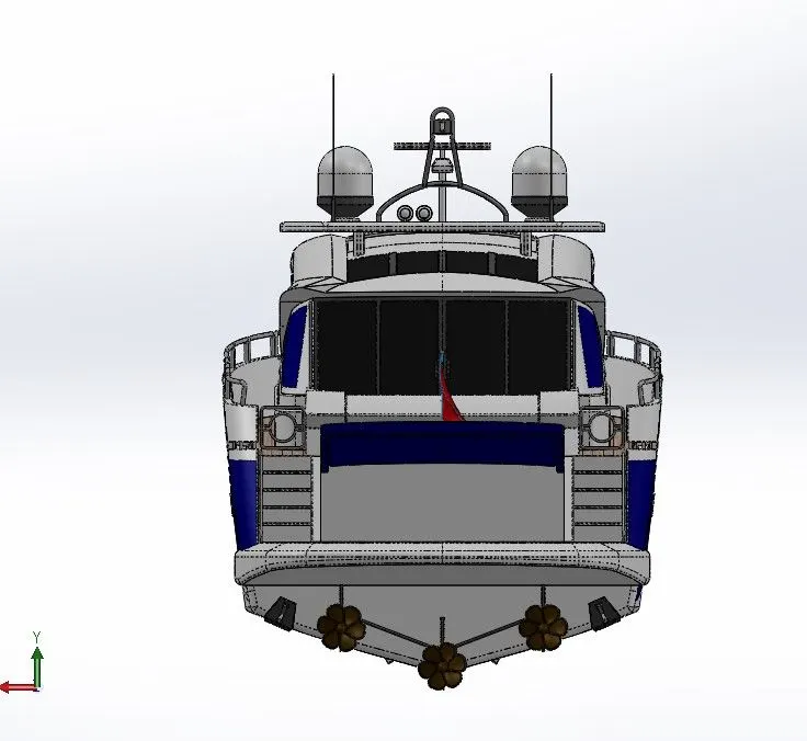 Fig83: Back
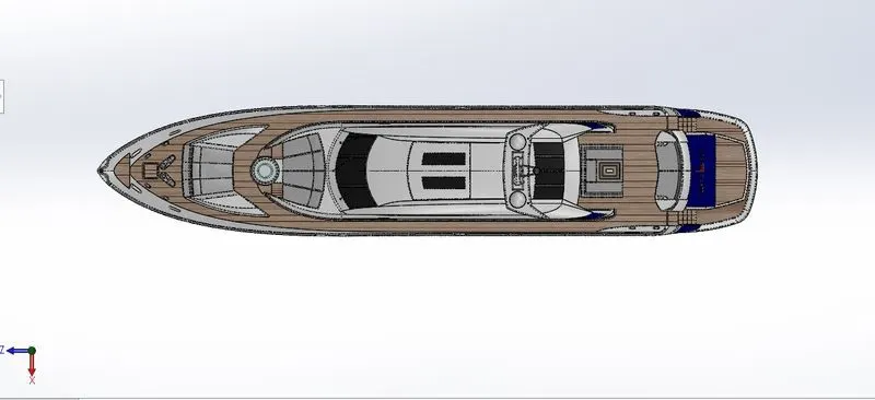 Fig84: Top
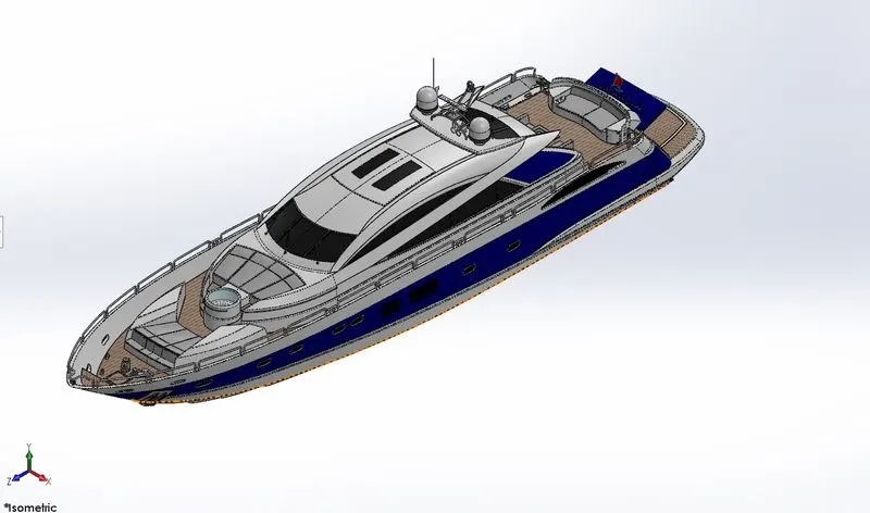 Fig85: Isometric
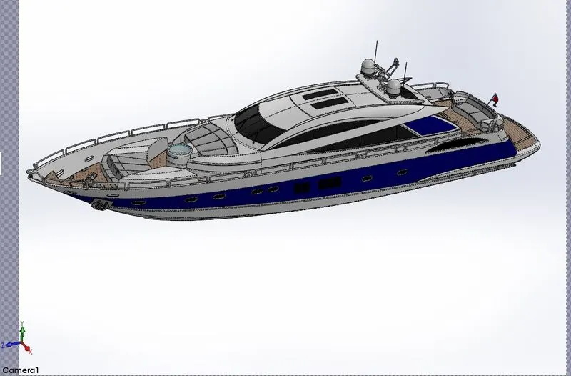 Fig86: Camera Setup View_1
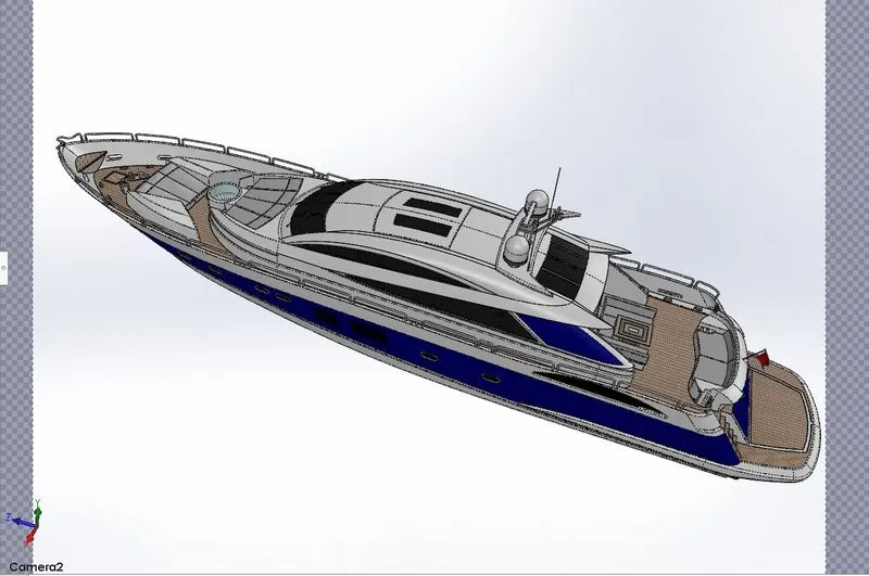 Fig87: Camera Setup View_2
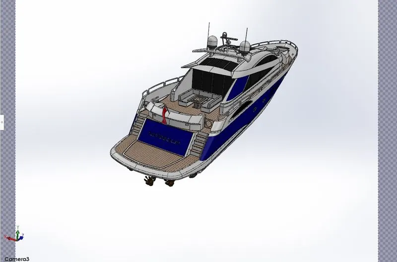 Fig88: Camera Setup View_3
Assembly Feature Tree:
RENDERING
Standard Views:
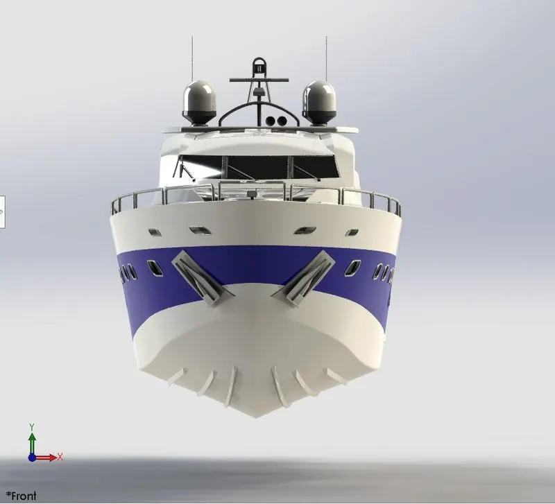 Fig89: Front
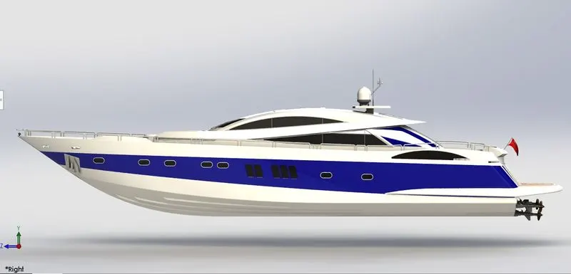 Fig90: Side
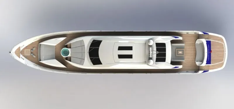 Fig91:Top
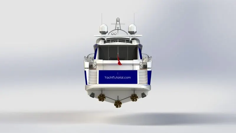 Fig92: Back
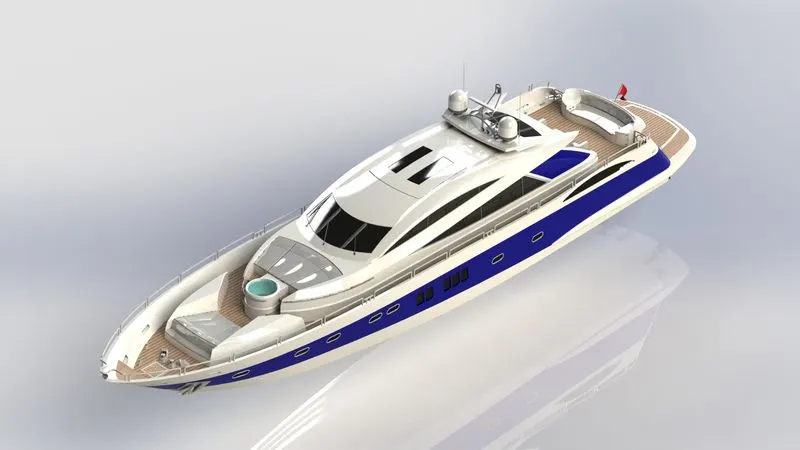 Fig93:Isometric
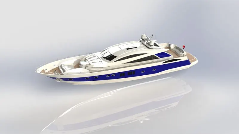 Fig94: Camera Setup View_1
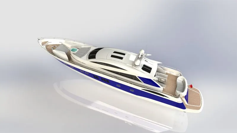 Fig95: Camera Setup View_2
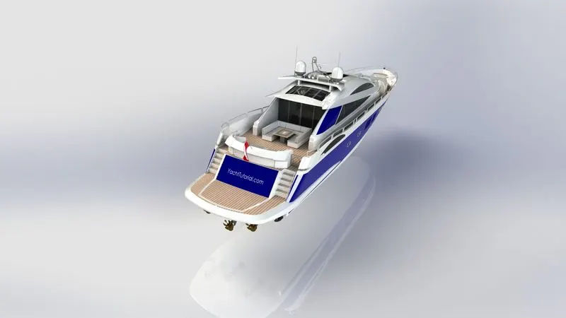 Fig96: Camera Setup View_3
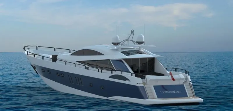
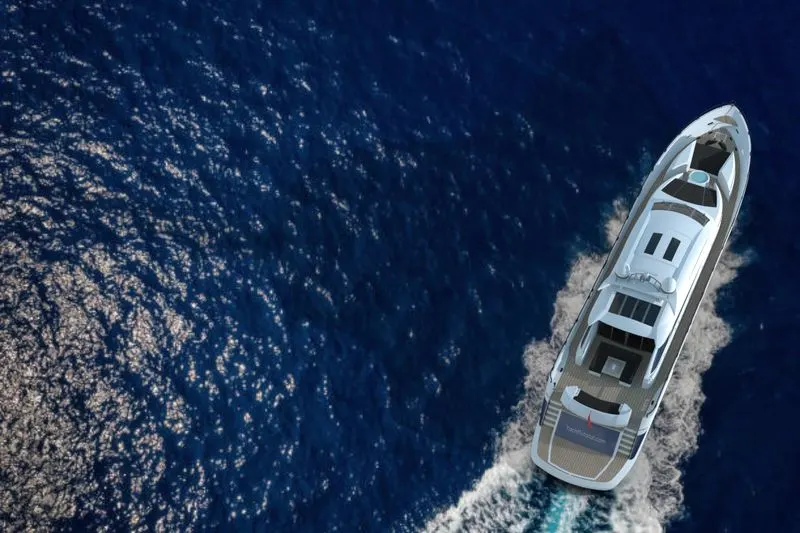
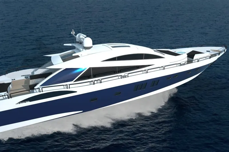
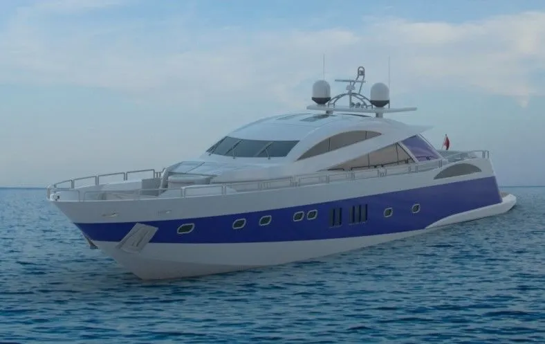
Solidworks Visualize Photorealistic renderings:
CONCLUSION
This project was successful in imparting the apt knowledge in Solidworks part modeling and assembly. Since the part modelling followed a gradual learning curve from simple to complex, the tools and features used could be understood in a comprehensive manner. I thank the support team at Skill Lync and my mentor Mr. Soundar Rajan for his continued support to successfully complete this project.