Surface modelling of an Aston Martin ONE-77 using Solidworks
Surface modelling of an Aston Martin ONE-77 using Solidworks
Objectives
- To familiarize with the basic concepts of surface modelling
- To learn how 2-D blueprints and transformed into complex surfaces using a combination of simple sketch tools and 3-D surface and solid modelling tools provided by Solid Works software
Introduction
Software- Solidworks
Originally developed by an MIT graduate Jon Hirschtick in 1993 and later acquired by a French software corporation, Dassault Systemes SE (abbreviated 3DS), in 1997, Solid Works is a solid modeling computer -aided design (CAD) and computer -aided engineering (CAE) computer program.
It utilizes a parametric feature -based approach. This means that the model can be accessed from any angle since it is dimensioned in a completely 3-D environment. This, in turn, ensures two important principles in designing- repeatability and changeability.
The 2019 version of Solidworks has been used in this project.
Target model- Aston Martin One-77
Built by the British Car Manufacturer Aston Martin, the One-77 is a flagship sports car of the two-door two-seater variety. Its production timeline was from 2009-2012 and it was only limited to 77 cars and hence, the name. Full carbon fiber monocoque chassis, hand crafted Aluminum body and naturally aspirated engine are some of its distinguishing features.
This project incorporated the powerful surface modelling tools available in Solid Works to develop the outer body of the car. The solid modelling tools were also used to develop the wheel and allied bodies. A blueprint of the vehicle was used as a reference for all the sketches.
Modelling- Solid vs Surface
Solid models are often preferred when the model has a further purpose to serve, such as in manufacturing, where the physical attributes play a key role both in process and tool selection. While there are many differences between solid and surface modelling, there is one which stands out- Organic shape construction.
Surface modelling is an excellent option to design organic shapes which are otherwise complex for a solid modelling platform. This is one the big reasons why surface modelling was preferred in this project as well, especially since every curve in an automobile is important both in performance and aesthetics, the latter being the key idea in this project.
However, when it comes to the best among the two, it is always better to have a combination to create the final model, especially if it involves assembly. As such, this project also incorporated a combination of both with the percentage of surface modelling tools used slightly more than the solid modelling ones.
Project Overview
Project outline
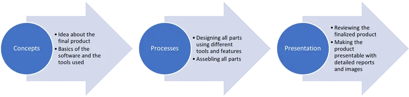
Design overview
Design flowchart
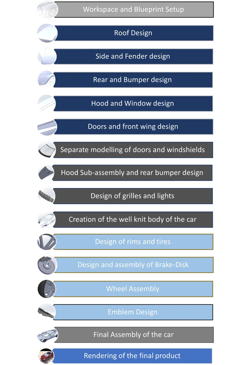
Design Stages
The entire project has been divided into sub sections based on the tools and processes applied.
- Set-up stage: The Workspace set up and arrangement of blueprints before beginning the design process.
- Phase-1: Modelling the body of the car using various surface modelling tools. The stages shown in the flowchart from the design of roof till the front wing design come under this phase.
- Phase-2: Splitting the body and modelling individual components in a separate workspace. The stages shown in the flowchart from the design of doors till the creation of the well knitted body of the car come under this phase. Some solid modelling tools were also used in this stage, in addition to the previously used surface modelling tools.
- Phase-3: Solid modelling of the Rims, tires, brake disk, caliper and the emblem all come under this phase. The entire wheel assembly was also created in this phase.
- Final stage: Assembling the entire model and rendering the model using suitable appearance attributes for the final presentation.
Features and tools
Surface
The following are the important surface modelling tools used:
Extrude, Sweep, Loft, Boundary Surface, Offset, Ruled Surface, Fill, Extend, Trim, Knit, Move/Copy
Solid
The following are the important solid modelling tools used:
- Boss/Base: Extrude, Revolve, Sweep, Loft, Thicken
- Cut: Extrude, With Surface
In addition to the above tools, there were a few tools common to both types of modelling that found extensive use in this project. They are:
- Pattern/Mirror: Linear pattern, Circular pattern, Curve driven pattern, Mirror
- Other features: Fillet/Round, Chamfer, Shell, Flex, Combine, Intersect, Split, Move/Copy, Delete/Keep body
Sketch Tools
The Sketch Picture tool was used to import the blueprints into the workspace. Most of the sketch tools used were basic like line, circle etc. The most important sketch tool used is the Spline. Also Offset and Convert entities tool were used to create sketches from existing sketches or edges.
Curve Tools
While the Projected Line tool was the mostly used tool in this category, the Split line tool was also used for projecting a sketch on to a face or a surface.
Reference geometry
One the most widely used feature in this project is the creation of reference planes with respect to existing planes or sketches. Since there were a considerable number of new planes, the naming of these planes was done based on the distance from the reference planes or sketches from which they were created. The creation of a reference axis was done for aligning the wheel in the final assembly.
Face
The Delete face tool was used on a few instances.
The important tools used for this project have been detailed in the explanation of various stages of the project.
Design Process
Units
The CGS unit system has been used for this project.
Set-up stage
Workspace and Blueprint setup
Blueprints, which are basically orthogonal drawings of the desired product, helps provide the foundation for starting any sketch. Hence, in this project too, importing the blueprints and setting them up in different planes (front, rear, top and side) was the starting point.
This step used the very first tool: Sketch Picture.
Once the sketch is begun on any plane, this tool can be used to import and position the blueprint corresponding to the view. Once all the blueprints have been arranged (refer picture below), the modelling process can be started.
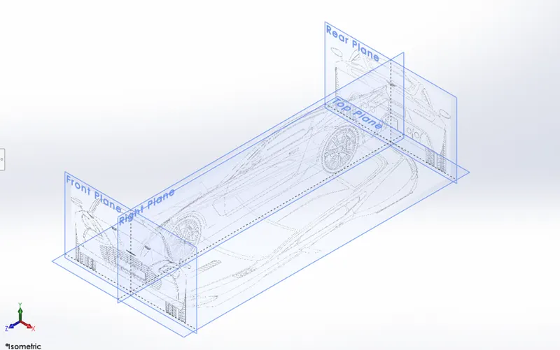
Fig 1: Blueprint setup (Isometric View)
The rear plane, which is not a standard plane available in the software, has been created using another tool, which has great importance throughout this project: Plane (Under Reference Geometry tool in the Features ribbon)
Since the model is symmetric, only one half was modelled, and the rest was mirrored to develop the final model.
Phase-1
Roof Design
This is the starting point for most automobile surface modelling, due to its relative simplicity. Also, this process introduced the most essential tools that were used repeatedly in this project.
Since the roof has a continuously curved structure, it needs the help of such profiles during the sketching phase as well. As such, Splines were used in the sketch with proper dimensioning. Splines in CAD are essentially a linear combination of the mathematical B- splines (basis splines) with a set of control points.
- Splines
Solid Works surfaces are based on a mathematical formulation called NURBS (Non-Uniform Rational B-Spline). It uses weighted points to define a curve.
As can be seen from the image below, the roof edge has been traced out by a spline. The end point of the spline has been defined from a reference plane (Side plane, in this case). Once this dimensioning is done, the handles, which allows complete control over the spline, is activated. The handle consists of three parts which has been described in the image below. The angle provides the direction whereas the weight (340, in this case) supplements the magnitude.
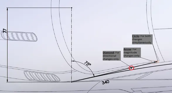
Fig 2: Left end point of the Spline (Roof design)
Since a sketch exists solely within a plane, it needs to be projected onto the 3-D environment, to finally transform it into an edge. As such, the Projected Curve tool was used with a combination of sketches, depicting the same edge from two different viewing angles, as the input.
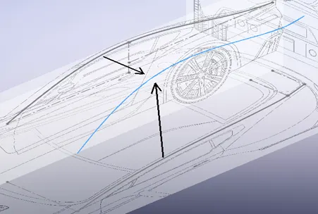
Fig 3: Projected curve (from Top and Side sketches)
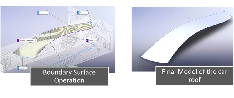
Using these tools, the four edges were set to finally move on to the desired purpose i.e., the surface modelling of the roof. For this task, the Boundary surface tool was chosen. Extra planes had been added with reference to existing planes to provide precision to the final product.
- Boundary Surface
Compared to other surface modelling features like Loft, this feature provides a greater degree of accuracy while working with complex shapes. A boundary surface uses two directions while defining a surface just like any other similar feature, except that it considers both directions as equally important and thereby provides curvature continuity to all sides. This specialty makes it one of the most used tools in any surface modelling operation.
Side and Fenders
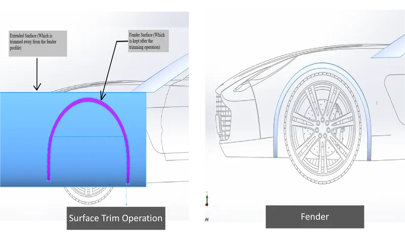
The design of fenders was done with a different approach. Rather than modelling the surface in accordance with the final shape directly, the surface for the fender was cut from a larger shape and then made to match.
For this larger shape to be made, the Surface-Extrude tool was used. This basically enables a sketch profile to be expanded in a specified direction, usually normal to the profile. The fender surface was then drawn and trimmed off from the extruded surface using the Trim Surface tool.
While modelling the side of the car, a projected curve specifying the top outline of the surface was needed. In contrast to older versions of Solid Works, the newer versions enable reusability of absorbed curves. If not, at this step, a new tool could also be used: 3d Sketch. Using this tool, a new geometry can be created in three dimensions by referencing bodies, planes, surfaces, or vertices which already exist.
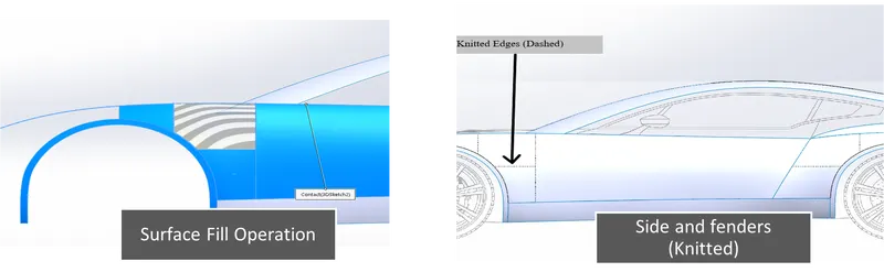
The surfaces present between both the fenders and the door could not be modelled using normal boundary surface tool since these surfaces had five edges which made it difficult to find two directions needed for modelling. For this purpose, a new tool was used: Surface Fill. This is relatively simple tool, which fills a gap between two or more specified targets based on the edges which forms the boundary of the gap.
For this tool to work correctly, every surface that surrounds the gap must be knitted together. To achieve this, another tool was chosen: Surface Knit. This combines two or more adjacent, non-intersecting surfaces together. For knitting, however, tolerance specification plays a key role in determining whether the surfaces can be perfectly knit or not. If the surfaces are knit properly, the joining edges will appear as dashed.
Rear and Bumper design
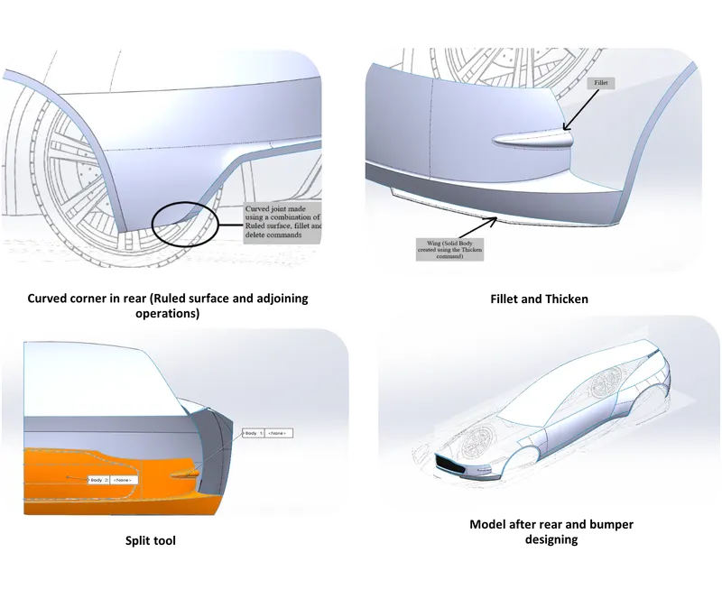
The rear design utilized all the previously used tools. However, the portion between the rear bumper and the fender needed a curved joint. Since this portion is an intersection of two edges, the Ruled Surface tool was used along with fillet, trim and delete tools to form a rounded corner, that was tangent to both the edges.
The front bumper too needed some new tools to make the final product. First of these was the Body- Move/copy tool which, as the names suggests helped in moving or translating an independent body/surface within the 3D workspace. This tool was particularly helpful in the design of the front bumper, since there was a tiny offset between the top and bottom portions. The next new tool that was introduced during this modelling was the Fillet/Round tool, which eliminated sharp edges along the bumper like the portion in the front bumper and gave a continuous curvature in the design, which is mostly important, from a manufacturing point of view.
The front bumper has wings beneath it which is effectively modelled as a solid body in this project using the Thicken tool.
Finally, the front bumper had an area which needed to be reserved for the grilles. This portion neeed to be separated from the rest of the bumper. To achieve this, the Split tool was used, which essentially creates multiple bodies from a single body.
Hood and Window design
While most of the tools used in this process was a repetition of the previously used ones, the window design incorporated a different type of fillet (Variable fillet) which blends different type of radii throughout the edge. The surfaces surrounding the wheel which connected with the fender were also designed in this stage using the Ruled surfaces tool.
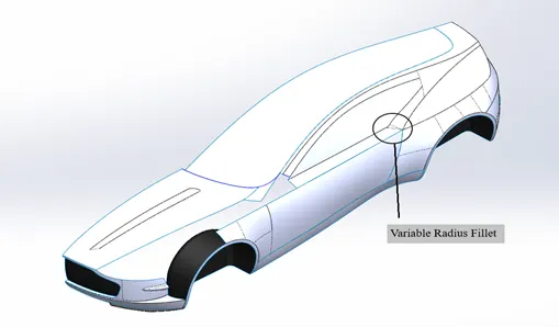
Fig 4: Hood and Window design
Doors and Front wing design
During the design process of the door, the isolate option in Solid works was useful to create the curved shape in the door that is a distinguishing feature of this car. While designing the front wing, a portion, which would later be occupied by the Lights of the car, was left off.
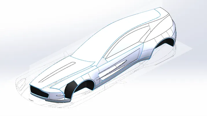
Fig 5: Door and Front wing
Phase-2
Design of doors and windshields
Until now, the model had been considered as one single body. To add details to individual components, the body needed to be split into smaller target bodies. This stage separated the door and roof from the rest of the body, so that they could be modelled separately by adding all the desired features.
First the roof was separated into three different portions. The front and rear portions were then exported separately into a new part file and finally modelled into the windshields of the car. The original surfaces which were exported from the body were made hidden to avoid any changes.
Similarly, the side portion of the car was also split to separately model the windows and door. The door modelling included the addition of the rear-view mirror as well. All these models which were separate part files were also mirrored about the symmetry plane and kept ready for the final assembly.
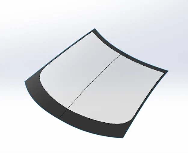
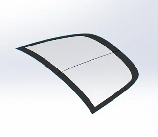
Fig 6: Front and Rear Windshields
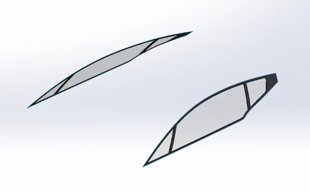
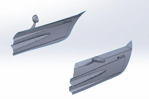
Fig 7: Windows and Doors
Hood sub-assembly and rear bumper design
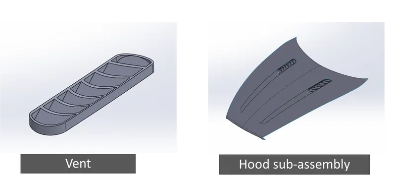
As can be observed from the real car, there are four vents in the front, two of which are present on the hood (heat vents) and two on the main body adjacent to the hood (air intake vents).
The hood was first separated from the body and worked on as a new part, while hiding the exported surface in the main body. While the hood itself required only previously used surface modelling techniques, the vents were modelled as a solid body.
The vent was first split from the base surface and then isolated, for ease of working. The fins which line the inner volume of the vents were made by using the Linear Pattern tool in the features ribbon. The slot and the fins were then made into one single solid body using the Combine tool. A similar approach was done on the air intake vents in the main body as well.
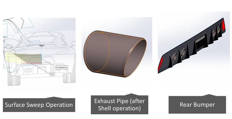
While designing the rear bumper, the first step was to leave a notch for the license plate. To achieve this the surface trim option was efficient. However, the surface to be trimmed, needed a tangency with the existing surfaces and hence the Surface -Sweep tool was chosen. It enabled to create a surface from a profile along a defined path. The spoiler was then separated from the rear and the details were added by working the part in isolation.
The rear bumper was then exported as a separate part. The exhaust pipes were modelled as a solid body by using appropriate tools. To empty the pipe the Shell tool was used. This removes material from a solid body and creates a thin-walled feature.
Suitable appearance was applied to different parts of the bumper and was set for assembly. Also, the corresponding surface in the main body was hidden to avoid any changes.
Design of Grille and Lights
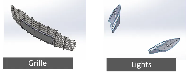
The front of the body was exported as a new part to act as a starting point for one of the most striking characteristics of the car- the grille.
A surface hull was created which was then trimmed according to specific profiles to create the entire grille and then combined into one solid body. The license plate was then modelled from a portion of the grille and made into another solid body.
The headlight portion was then detached from the main body and exported as a new part. Using appropriate tools, the details such as the light bulb, LED array etc. was modelled and the entire part is kept ready for assembly.
Designing the well knitted body of the car
The remaining operation in the main body was to mirror all the existing features about the symmetry plane. Before this process, any remaining unknitted surfaces were knitted using appropriate tolerances. After mirroring the entire body, all contact surfaces were knitted together and kept ready for the final assembly.
An extra detail which was added in the body was that of the fuel tank lid towards the rear of the body.
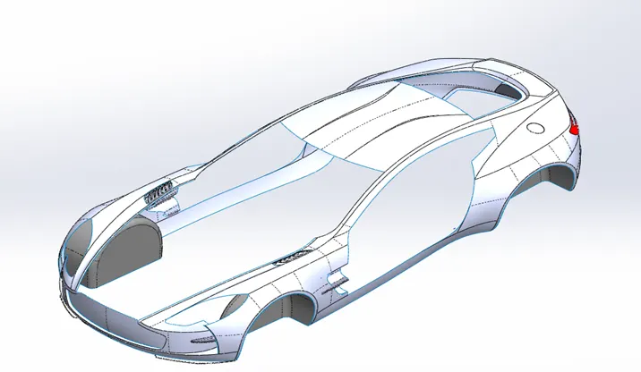
Fig 8: Well knitted body of the car
Up to this stage, surface modelling was the predominant mode of design. The remaining portions such as the wheel were modelled using solid modelling techniques.
Phase-3
Wheel and Tires design
The first part designed during this stage was the wheel rim. Two separate rims were modelled since the rear rim needed to be wider than the front. For ease of modelling, one rim was modelled completely and saved twice and then the second rim was created by editing the base sketch of the second file. The same approach had been taken for design of the wheel as well.
Even though solid modelling tools were used before, the details of these tools are added in this section of the report since they found extensive use during this stage.
Revolve: This tool revolves a sketch or a profile about a specified axis and was used to revolve the base sketch of the rim as well as the tire.
Cut-Extrude: This tool extrudes a sketch or a profile in a specified direction to cut through a solid body and was used to create the rim pattern.
Cut-Sweep: This tool cuts a solid body using a closed profile along a specified path and was used to remove small volumes from the tire to get the cut pattern along the edges.
Boss-Extrude: Works similarly to surface extrude and extends a profile or sketch in a specified direction to create a solid body and has been used in all solid extrusion processes in this project.
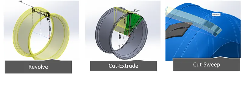
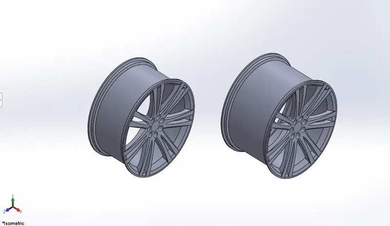
Fig 9: Front and Rear Rims
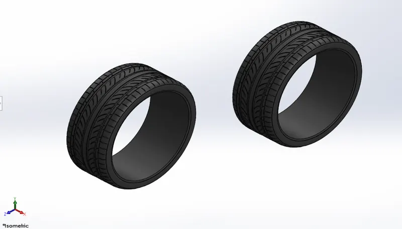
Fig 10: Front and rear tires
Brake Disk Sub-assembly
Two solid disks were modelled using solid modelling tools and then joined together using a circular pattern of extruded solid bodies.
The caliper was then modelled as a separate part using an existing blueprint.
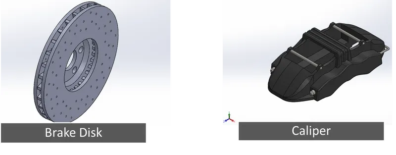
Once both these parts had been modelled, they were assembled and saved.
Assembly: An assembly a combination of parts or components that have a specified relation to each other. This relation is termed as a Mate. Two mating parts in Solid works can have various mating relations based on user specifications and geometry.
Majority of the components for this project were coincident mates which means their sketch planes were aligned together for coincidence.
In the brake disk sub-assembly however, the mates used were as follows:
Concentric mates: Between the cylindrical face inside the caliper and the cylindrical face on the disk surface.
Width mate: This is an advanced mate used to disk inside the caliper’s groove. For this purpose, the inner faces of the caliper’s groove and the outer faces of both the disks were chosen.
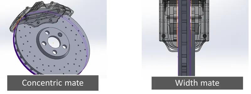
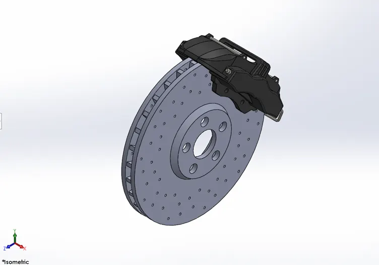
Fig 11: Brake disk sub-assembly
Wheel Assembly
The Tyre, rim and the brake disk sub assembly were assembled to form the entire wheel of the car. A copy of the file had been used to create and extra wheel assembly model for the rear wheel as well.
While the mating relations between the tyre and the rim were concentric and coincident, the brake disk sub assembly was given a distance mate relation with the rim, so that it could be placed within the rim.
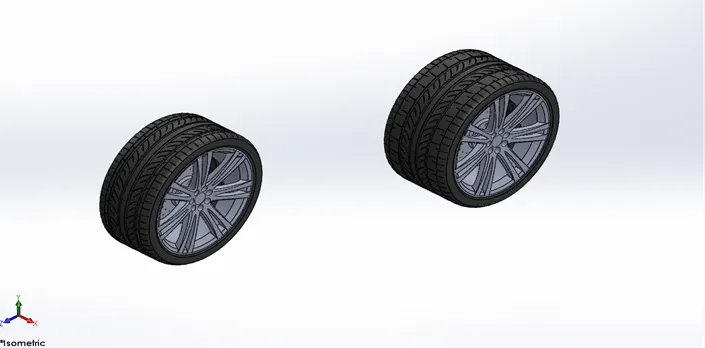
Fig 12: Wheel assembly
Emblem Design
The iconic Aston Martin Emblem was modelled using an original image as the blueprint. Solid modelling tools were extensively used to create the emblem and the Flex tool was used to bend the emblem so that it could fit correctly with the surfaces on which it was to be placed.
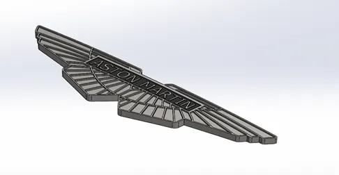
Fig 13: Emblem
Final stage
Model Assembly
Even though during the project most assemblies were done upon completion of individual components the entire assembly operation details have been added on this section of the report.
First the main body was opened in a new assembly window. The first individual part which is the front windshield was then added using the Insert components option in the assembly ribbon. Apart from the main body, which is the first part, every other imported component could be moved freely through the workspace. To fix these “floating” parts, coincident mates were used. The sketch planes of the windshield were aligned to the assembly window’s sketch planes by using coincident mates. For the main body however, before adding mates, the body had to be made free using the Float option in the right click menu on the body. This process of importing and adding mates was repeated for every other components to complete the initial assembly.
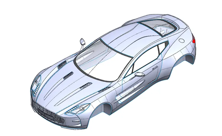
Fig 14: Assembly (Before importing the wheels and emblem)
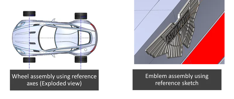
For the wheel to be aligned however, a coincident mate was inappropriate since it does not have any direct contact with body surfaces. For this purpose, two new axes were defined in the main body using the front plane as a reference. Using a combination of coincident and distance mates, the wheels were perfectly aligned with the axes and thereby with the body as well.
Sketches using inclined lines were used as a reference for assembling the emblem on to the body. In this case, along with a standard coincident mate, a tangent mate was also used to perfectly align the emblem both at the front and back of the car. With this the entire assembly had been completed and the model was ready to be rendered for presentation.
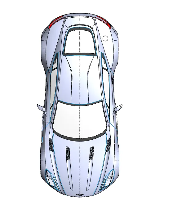
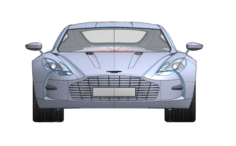
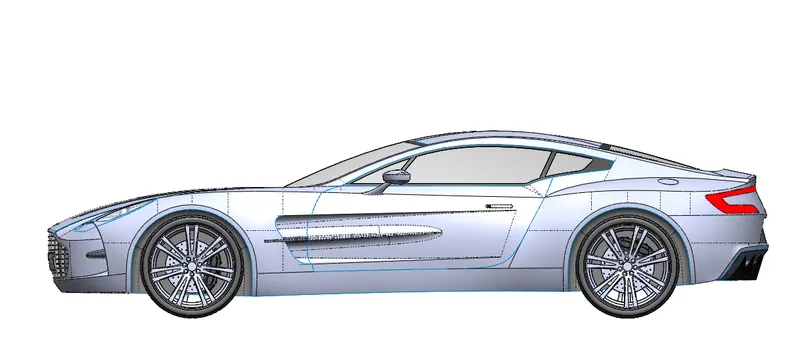
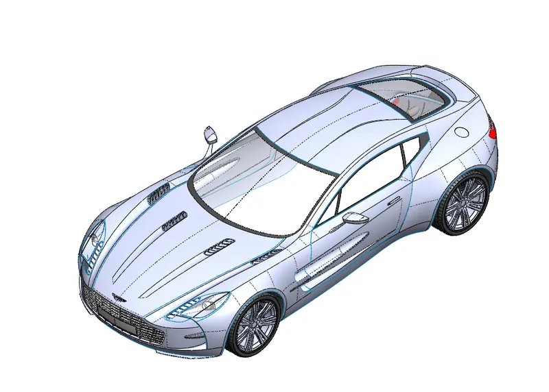
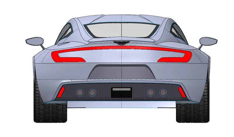
FINAL ASSEMBLY- STANDARD VIEWS
TOP VIEW
FRONT VIEW
SIDE VIEW
ISOMETRIC VIEW
BACK VIEW
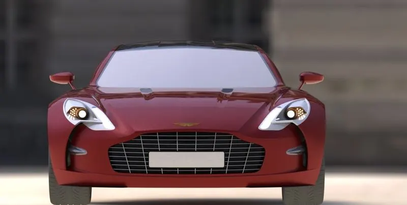
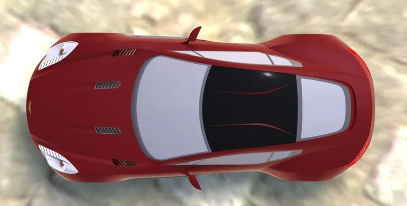
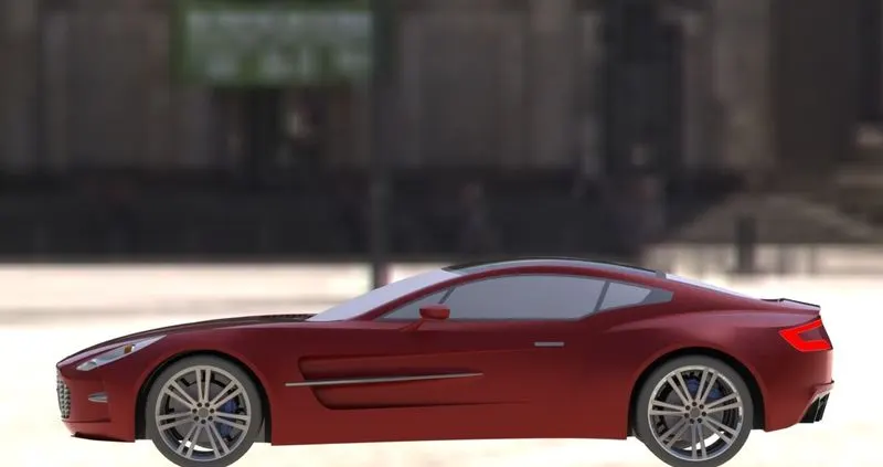
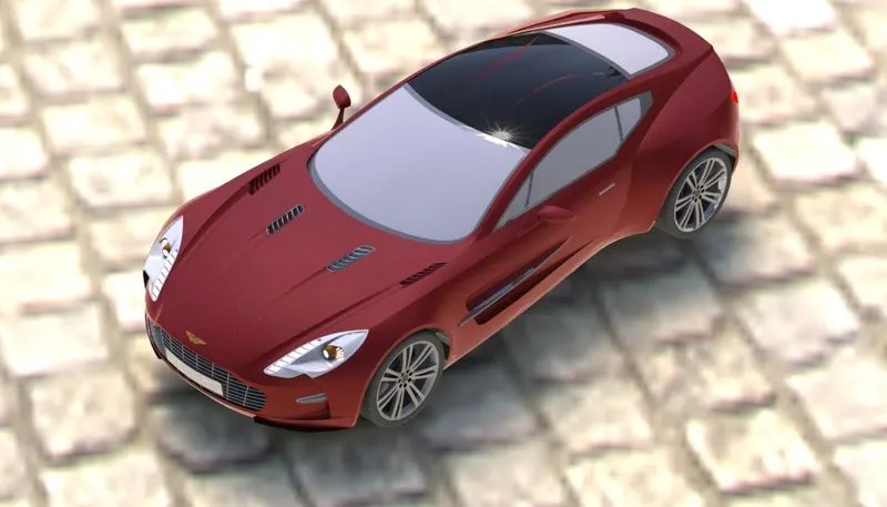
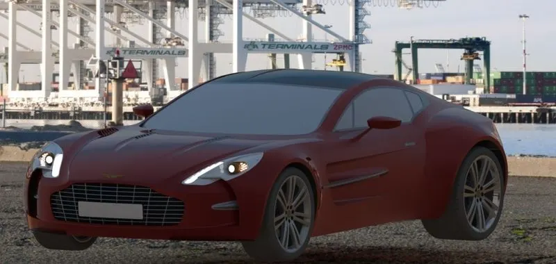
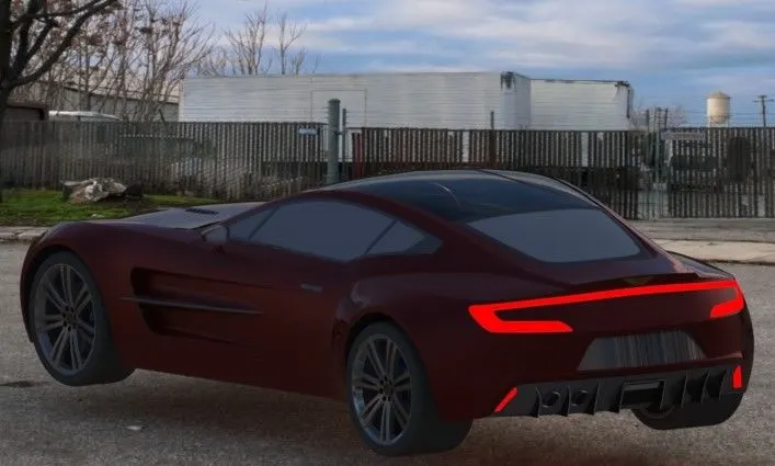
PHOTOREALISTIC RENDERING OF THE MODEL
A photorealistic rendering of the completed model has been done with the help of Photoview 360 in Solid Works.
CONCLUSION
This project successfully achieved in imparting a great deal of knowledge regarding simple and complex surface modelling tools in Solidworks.
I thank the team at Skill-Lync especially my mentor Mr. Akshay for supporting and guiding me through various stages of this project.