Advanced Sheet Metal Design Using NX Cad Challenge_2_Box Assembly
SHEET METAL BOX ASSEMBLY USING NX CAD
OBJECTIVE
Modelling a box assembly using the sheet metal tools and features in NX CAD environment and creating a detailed drawing of the same.
INTRODUCTION
Software
Formerly known as Unigraphics, NX is an advanced CAD/CAM/CAE owned by Siemens PLM Software. It utilizes a parasolid geometric modeling kernel and is mostly used when advanced modeling features are required in a product. The ownership of the software belongs to the American Software company, Siemens (owned since 2007).
The NX 10 version has been used in this project.
Sheet metal
One of the fundamental forms used in metalworking, sheet metals are thin pieces which can be cut and bent into a variety of shapes. Thickness can vary from 0.5mm to 6mm. This process has been employed in this project to ensure a realistic approach in designing the part.
Target Model
The model chosen for this project is a sheet metal box assembly. A lid for the box was also designed along with hinges.
DESIGN METHODOLOGY
Process Flowchart
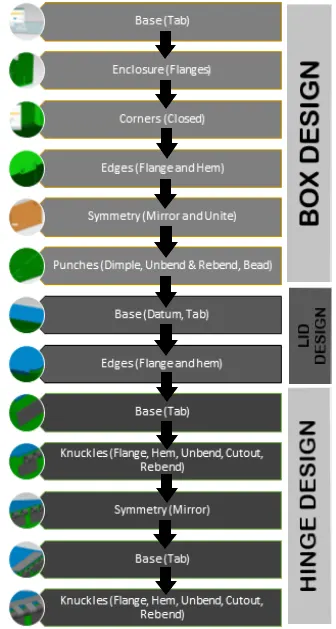
Features and Tools used
- Sketch: Rectangle, Line, Circle, Round (fillet)
- Sheet Metal(Basic): Tab
- Bend (SM*): Flange, Hem
- Corner (SM): Break Corner, Closed corner
- Punch (SM): Dimple, Bead
- Feature (SM): Normal Cutout, Mirror feature
- Form (SM): Unbend, Rebend
- Drafting: Base View
- Datum Plane
[* - Sheet Metal]
DESIGN PROCESS
UNITS
This project has been done using Millimeters as the base unit.
PROCESSES
1.Designing the box
- The base of the box was created by using a rectangle under the sketch tools on the XY plane and then using the Tab feature from the sheet metal application. A thickness of 1mm was chosen under sheet metal preferences before beginning the project.
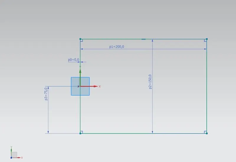 Fig1: Base Sketch
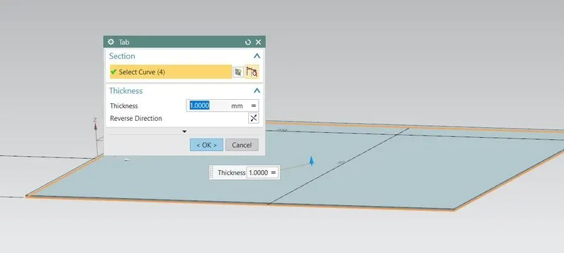 Fig2: Tab feature
- The four edges of the tab were used as references for the design of side faces using the flange feature.
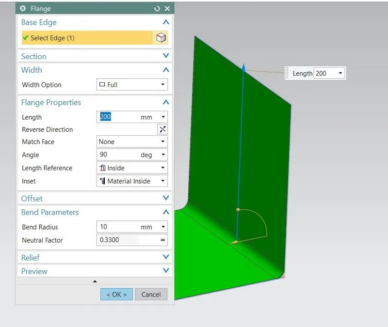 Fig3: Flange feature
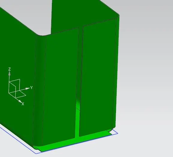 Fig4: Side face created using flanges
- The open corners created after the flanges were formed were closed using the Closed corner feature.
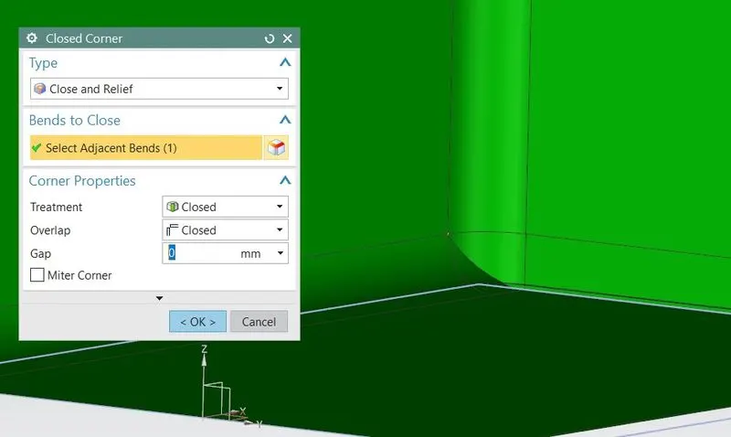 Fig5: Closed corner feature
- A set of flanges were created to close the gap in between the flanges perpendicular to the XZ plane. These new flanges were then designed into an open loop using the Hem feature. This signified a joint.
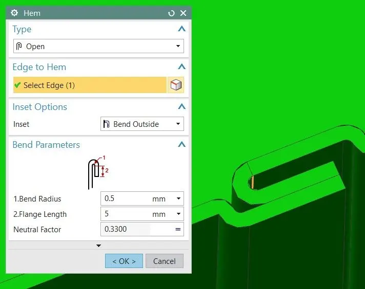 Fig6: Hem feature
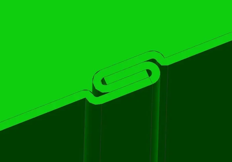 Fig7: Joint created using flange and hem features
- The entire model was then mirrored about the YZ plane using the Mirror feature to create a symmetric model.
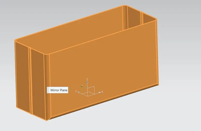 Fig8: Mirror feature
- The two portions were then joined into a single body using the Unite feature.
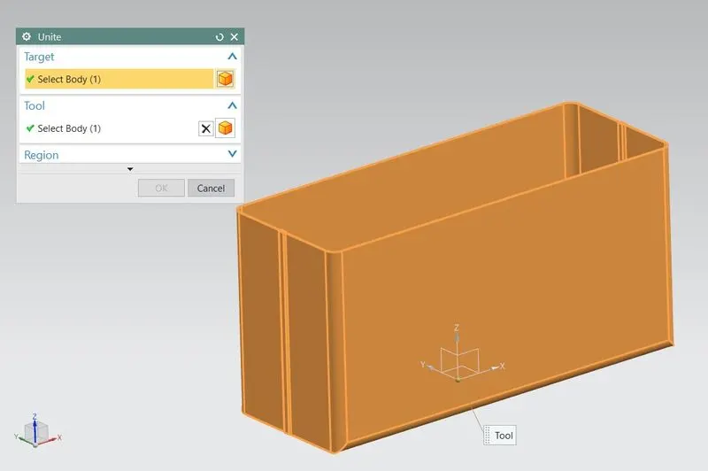 Fig9: Unite feature
- An appropriate sketch was created on the side face to use for the Dimple feature. Once this was created, it was mirrored about the XZ plane to create the dimple on the other face as well. Another dimple was created on the bottom face.
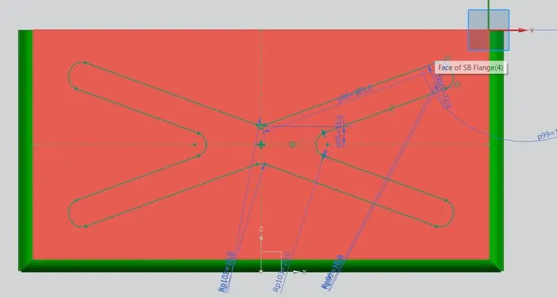 Fig10: Sketch for the dimple feature
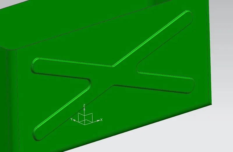 Fig11: Dimple feature
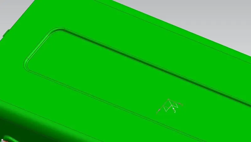 Fig12: Dimple on the base
- The model was then spread out using the Unbend feature and then restored using the Rebend feature.
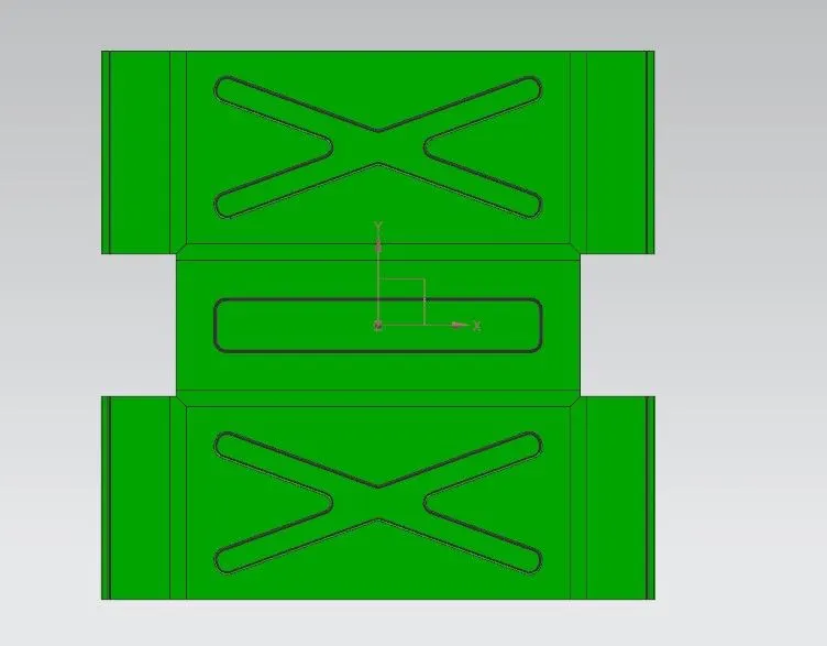 Fig13: Unbend feature
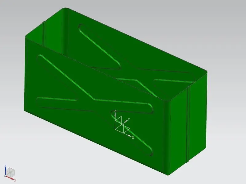 Fig14: Rebend feature
- A circular sketch was created at the base to create another punch attribute using the Bead feature. This bead was then mirrored to form three more at the base.
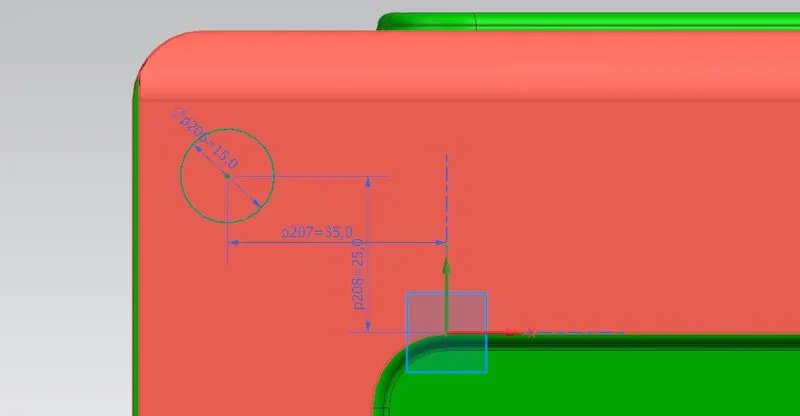 Fig15: Sketch for bead feature
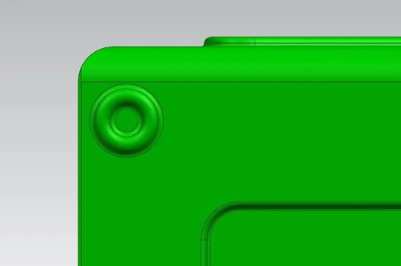 Fig16: Bead feature
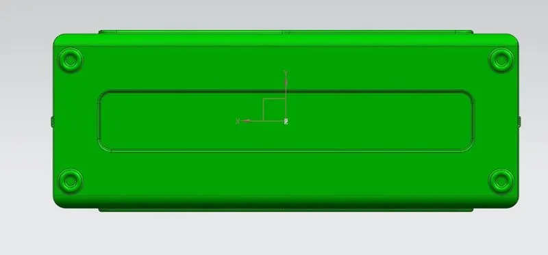 Fig17: Bead features (after mirror)
- The top edges of the side flanges (except the left face) were smoothed using the Hem feature.
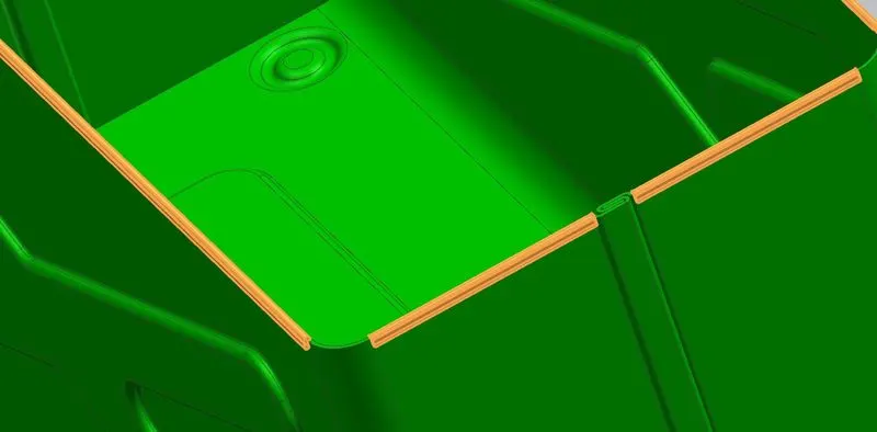 Fig18: Hem feature applied on the side flanges
2. Designing the lid
- To create the sketch for the lid, a new plane needed to be created at a certain distance from the base of the box. This was done using the Datum feature.
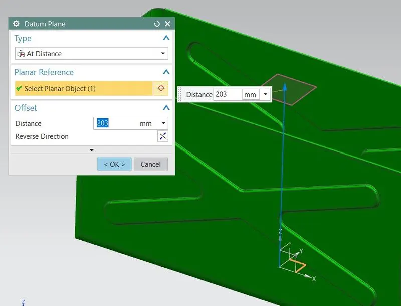 Fig19: Datum feature
- The lid was then created using the Tab feature. The edges of the lid were smoothed using flanges which properly covered the flanges of the box edges.
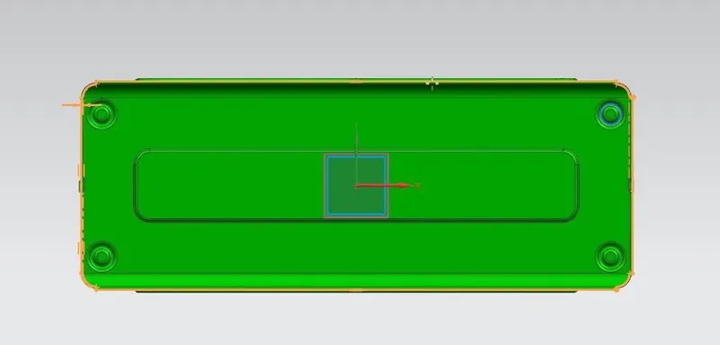 Fig20: Sketch for the lid
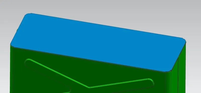 Fig21: Tab feature to create the lid
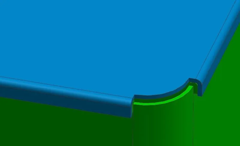 Fig22: Flanges on the lid
3.Designing the Hinge
- In order to add a feature which created a realistic take on this assembly, a hinge had to be designed at the right end of the lid and the box. A sketch was first created on the face of the box parallel to the YZ plane to model the base of the bottom half of the hinge. The Tab feature was then used to create it.
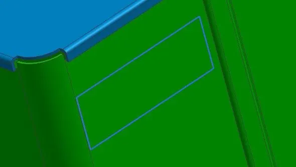 Fig23: Sketch for the base of the bottom hinge
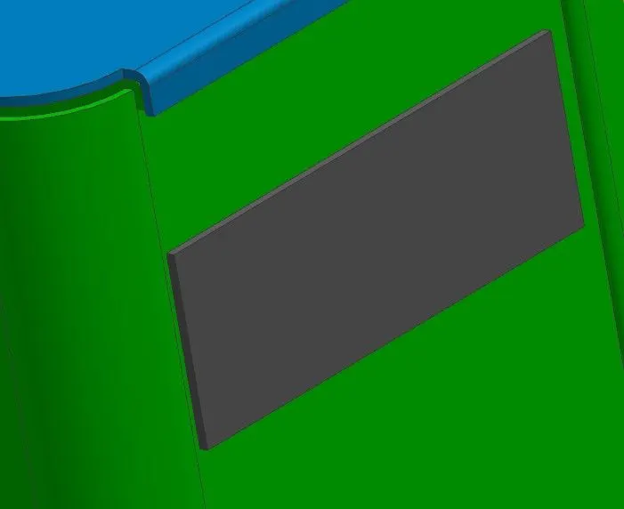 Fig24: Tab feature for the base of the bottom hinge
- To create the locking portion for the hinge, a flange feature was first applied and then a hem feature with an open loop was added.
 Fig25: Flange and hem for the bottom hinge
- The flange and hem were then straightened using the Unbend feature to create partitions. The partitions were created using a sketch on the unbent faces to remove material using the Normal Cutout feature. The hinge was then reverted to its original shape using the Rebend feature.
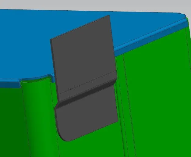 Fig26: Unbend feature
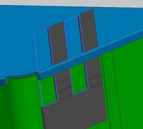 Fig27: Normal Cutout feature
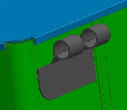 Fig28: Rebend feature
- In order to have another hinge about the symmetric plane, the Mirror feature was used.
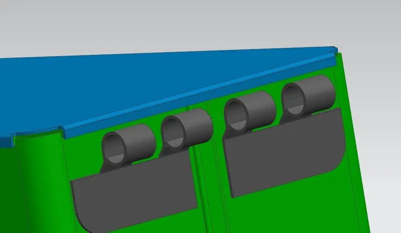 Fig29: Mirror feature
- Another set of hinges were designed using the same processes- Tab, Flange, Hem, Unbend, Normal Cutout, Rebend- to be placed on the lid. This step completed the design of the box assembly. Appropriate appearances were given to the parts.
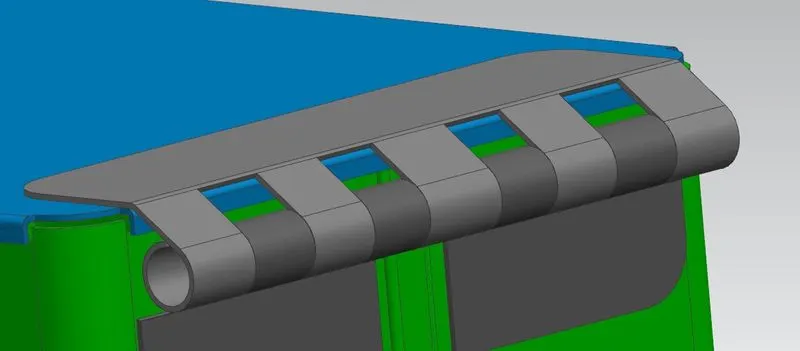 Fig30: Hinges
STANDARD VIEWS
- TOP VIEW (Fig 31)
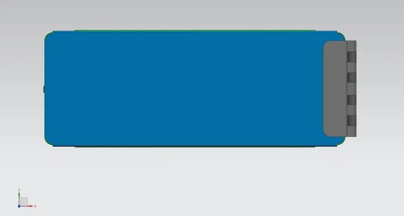
- FRONT VIEW (Fig32)
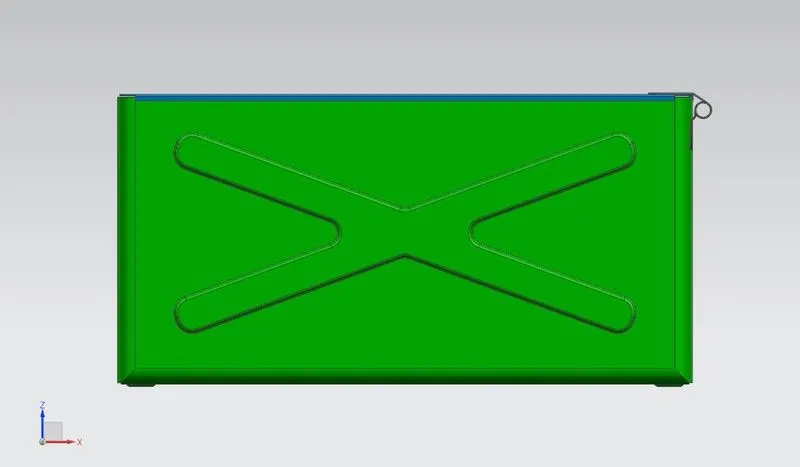
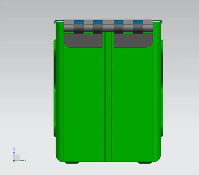
- SIDE VIEW (Fig33)
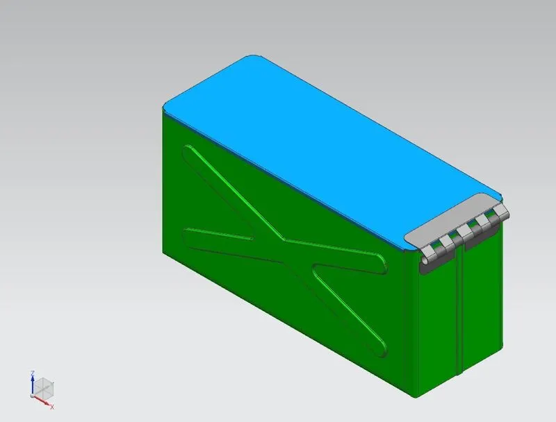
- ISOMETRIC VIEW (Fig34)
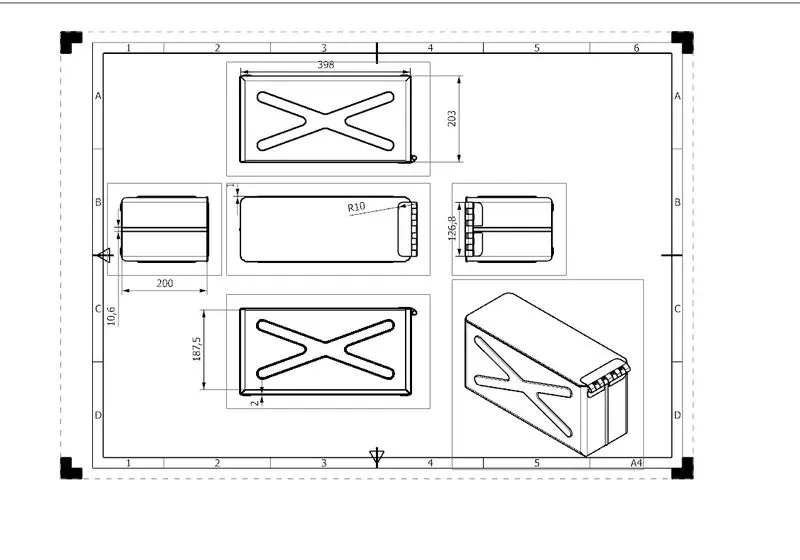
DETAILED DRAWING SHEET (Fig35)
CONCLUSION
The box assembly model took the basic sheet metal modeling tools available in NX CAD and utilized them in an innovative manner to create complex geometries. By following a systematic approach in the design process, the final product was modeled in a successful manner.