Week 9 - Attachment Feature Creation - Challenge 1
REASON FOR CREATION OF RIBS IN PLASTIC COMPONENTS.
It’s not uncommon for a small Plastic Injection molded part to be expected to hold up under a large load. One of the ways to strengthen a part is by adding one or more “ribs” to the design. Ribs are thin protrusions that extend perpendicular to a wall or plane to provide added stiffness and strength.
Designers commonly try to increase the strength of a part by making its walls thicker. Unfortunately, walls that are too thick are subject to warpage, sinking, and other defects. The advantage of using ribs is that they increase the strength of a part without increasing the thickness of its walls. Because less material is required, ribs can be a much more cost-effective solution as well.
RIBS.
Ribs are indispensable functional structures on many plastic parts. It can effectively improve the rigidity and strength of plastic parts like the H beam. By using ribs, it is not necessary to greatly increase the wall thickness of the plastic parts, and ribs are not undercut structures like the H beam whose structure will be difficult to make for plastic injection molding. So ribs work well for plastic parts that are subject to pressure, torsion and bending. Ribs can also act as internal flow passages to aid in the plastic melt filling flow, which is of great help to the formation of complex and large plastic parts.
Ribs are generally designed on the non-appearing surface of the plastic part, and its direction is as close as possible to the flow direction of plastic melt filling. Ribs should neither be too long nor too thick, otherwise, it will increase the difficulty of injection molding, causing problems such as voids and sink marks on the back.
Designing with Ribs in Mind
The position and orientation of a rib relative to load and reaction forces are critical to its effectiveness. By being conscious of part geometry, designers can ensure that ribs added to the design will improve bending stiffness. Here are some rules of thumb to keep in mind during the design process:
Rib thickness
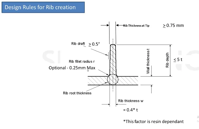
Ribs should be designed to be 50-60 percent of the nominal wall thickness. Thinner does not provide much structure and may be hard to fill. Thicker ribs are tempting, but they can begin to introduce sinks on the cosmetic surface.
Rib height
For maximum effectiveness, rib height should be no more than three times the nominal wall thickness. Since the rib will be thinner than the wall, it may be hard to fill it if it is taller.
Rib spacing
Increase the number of ribs rather than their height in order to increase stiffness. Ribs should be spaced a minimum of two times the nominal wall thickness apart from one another.
Rib draft
A minimum 1 degree draft will ensure that they release from the tool during molding.
Rib coring
Core thick ribs from the back or below to create a blank area and thinner rib walls. This will help mitigate cosmetic sinks.
Rib radii
Radii at feature intersections should be a minimum of 0.5 - 1.0x nominal wall thickness to increase rib strength.
PROCEDURE
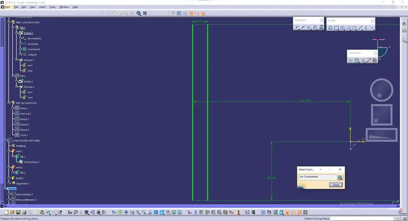
*Ribs are created with 6mm apart from each other and the sketch being iso constrained.
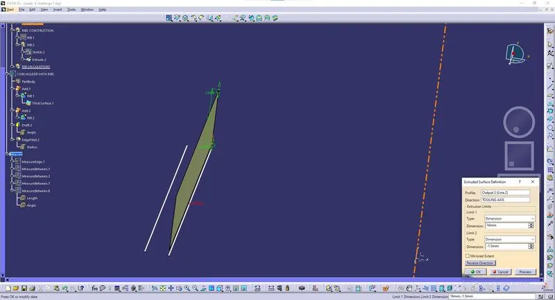
*Extrusion is created with respect to tooling axis.
*Rib is created by using thicken surface by 1mm.
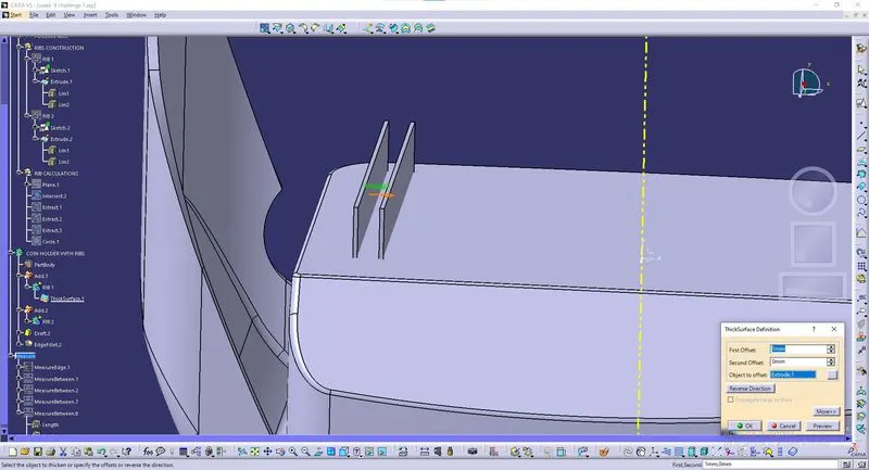
*Draft are provided with a value of `0.5^0`.
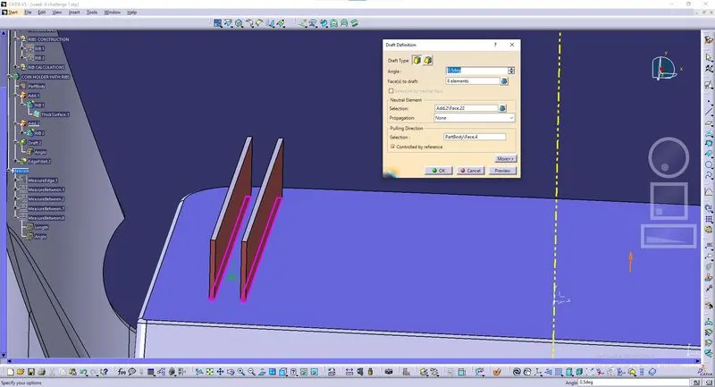
*Fillets are provided with a value of 0.25 mm.
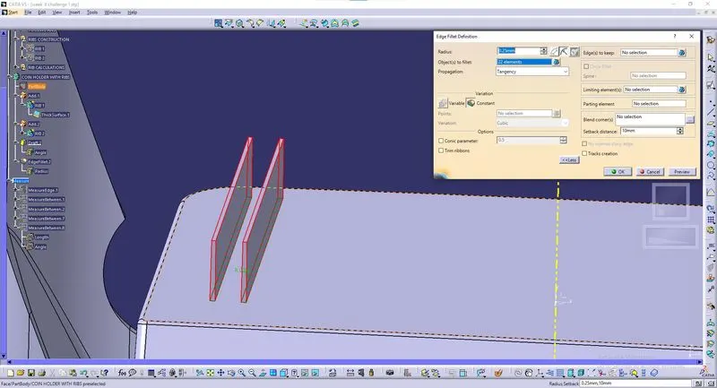
*Intersectional view for rib with measurements.
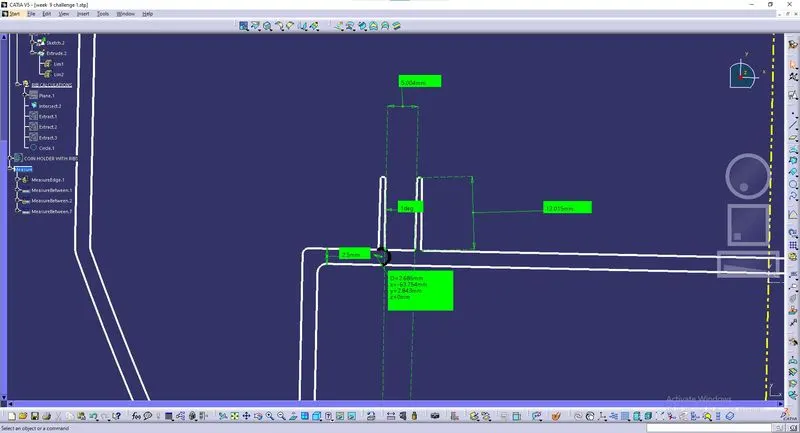
*Detailed view for rib with measurements.
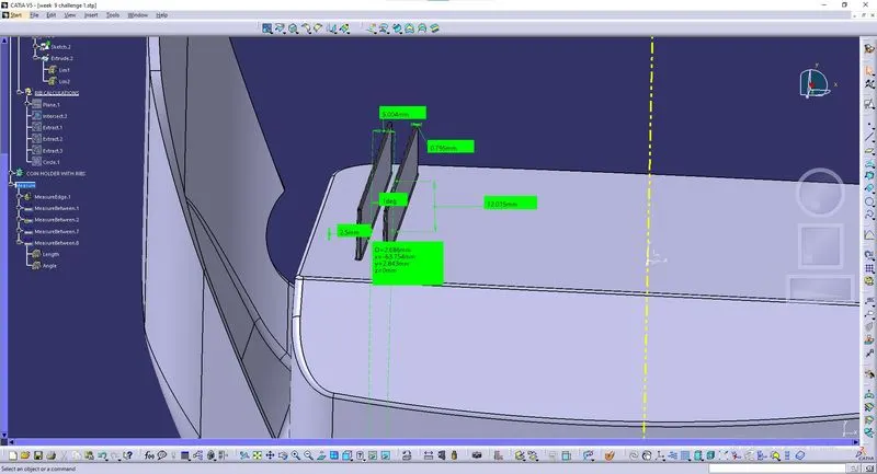
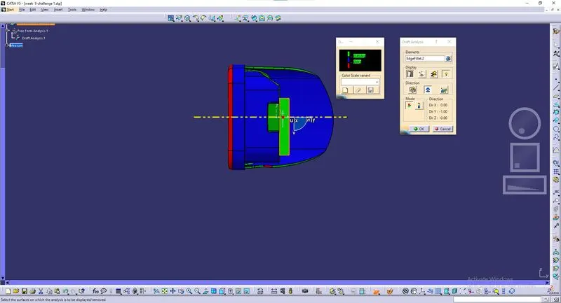
*Draft analysis for the Coin Holder with Ribs by quick analysis mode.
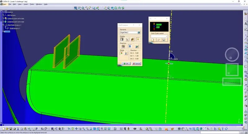
*Draft analysis for the Coin Holder with Ribs by Full analysis mode.
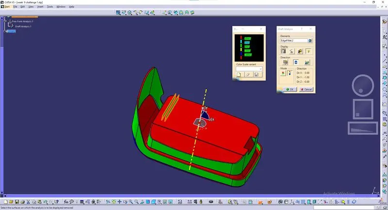
*Draft analysis for the Coin Holder with Ribs in Isometric view.
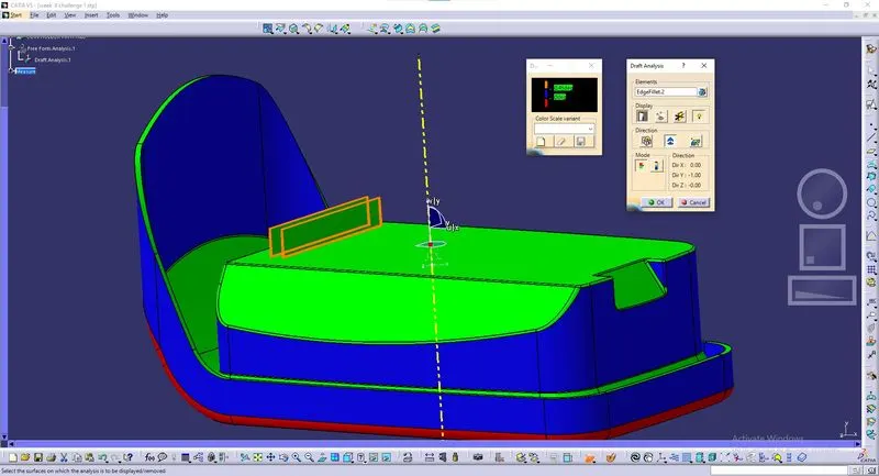
*Draft analysis for the Coin Holder with Ribs in Top view.
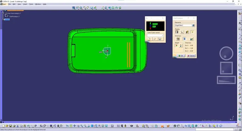
*Draft analysis for the Coin Holder with Ribs in Side view.
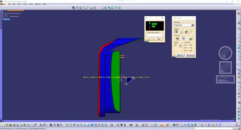
*Draft analysis for the Coin Holder with Ribs in Front view.