Week 8 - Simulating Cyclone separator with Discrete Phase Modelling
Aim: To perform analysis on cyclone separator and calculate the separation efficiency and pressure drop.
Introduction:
Cyclone separators are separation devices that use the principle of inertia to remove particulate matter from flue gases. Cyclone separators is one of many air pollution control devices known as pre-cleaners since they generally remove larger pieces of particulate matter. This prevents finer filtration methods from having to deal with large, more abrasive particles later on. In addition, several cyclone separators can operate in parallel, and this system is known as a multi-cyclone.
It is important to note that cyclones can vary drastically in their size. The size of the cyclone depends largely on how much flue gas must be filtered; thus, larger operations tend to need larger cyclones. For example, several different models of one cyclone type can exist, and the sizes can range from a relatively small 1.2-1.5 meters tall to around 9 meters.
Components and Design
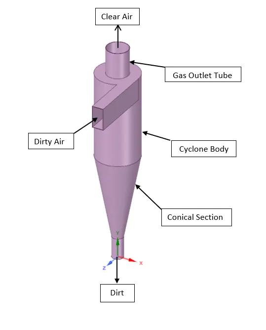
A reverse flow cyclone separator is an industrial assembly with no moving parts and a simple design.
The main cylindrical part of the cyclone separator is known as the body. The gradually narrowing conical section is known as the cone. Un-treated gas enters tangentially through the inlet at the side of the separator. Entrained particles within the gas stream are separated from the gas stream and discharged through the reject port at the base of the separator. Cleaned gas exits through the accept port at the top of the separator.
Working:
Cyclonic separation is a means of separating different liquid phases (different liquid densities) or separating particles from a gas stream. Cyclone separators often form part of a pre-cleaning stage prior to a gas or liquid being discharged.
Cyclone separators work much like a centrifuge (A centrifuge works by spinning objects around a centre axis. This spinning pushes harder on dense material than on less dense material which separates objects by their densities.), but with a continuous feed of dirty air. In a cyclone separator, dirty flue gas is fed into a chamber. The inside of the chamber creates a spiral vortex. The lighter components of this gas have less inertia, so it is easier for them to be influenced by the vortex and travel up it. Contrarily, larger components of particulate matter have more inertia and are not as easily influenced by the vortex.
Since these larger particles have difficulty following the high-speed spiral motion of the gas and the vortex, the particles hit the inside walls of the container and drop down into a collection hopper. These chambers are shaped like an upside-down cone to promote the collection of these particles at the bottom of the container. The cleaned flue gas escapes out the top of the chamber.
Most cyclones are built to control and remove particulate matter that is larger than 10 micrometres in diameter. However, there do exist high-efficiency cyclones that are designed to be effective on particles as small as 2.5 micrometres. As well, these separators are not effective on extremely large particulate matter. For particulates around 200 micrometres in size, gravity settling chambers or momentum separators are a better option.
Out of all of the particulate-control devices, cyclone separators are among the least expensive. They are often used as a pre-treatment before the flue gas enters more effective pollution control devices. Therefore, cyclone separators can be seen as "rough separators" before the flue gas reaches the fine filtration stages.
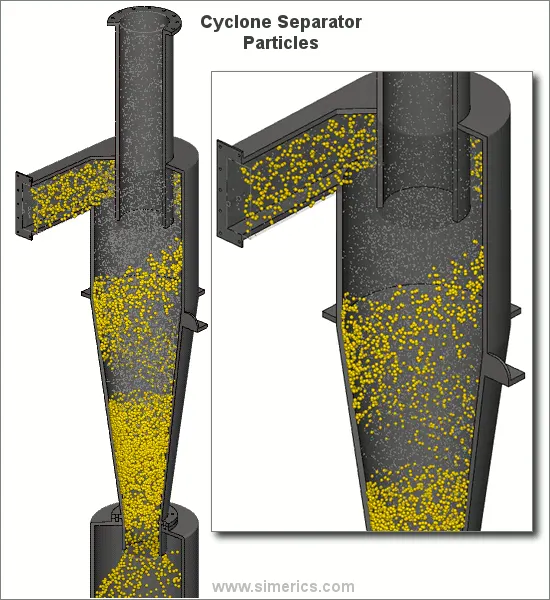
spiral formation and the separation
Gas containing entrained particles enters at high velocity through the tangential inlet at the top of the cyclone. The gas flows into the cyclone body/barrel at a tangent and begins to flow in a circular downward spiral towards the lower reject port; this downward flowing spiral is referred to as a spiral vortex.

The cone diameter gradually decreases which causes the gas velocity to increase. The outer vortex creates an additional inner vortex closer to the centre of the separator body and this inner vortex flows spirally upwards towards the accept port.
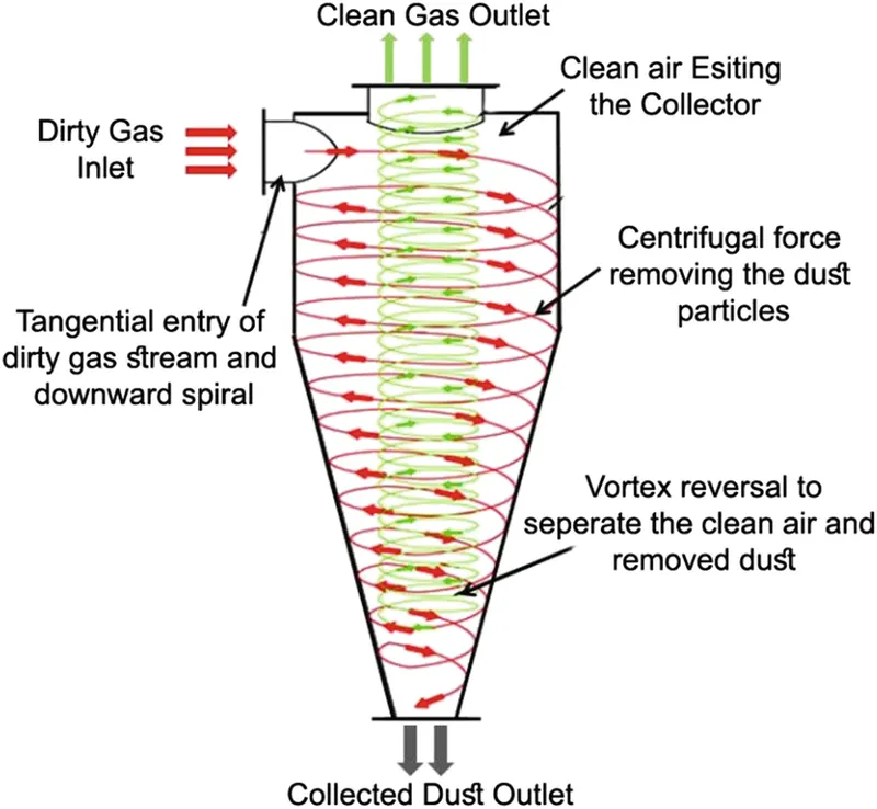
Particles with more inertia will impact with the side of the cyclone whilst particles with lower inertia will remain within the gas stream. Inertia can be thought of as a particle’s ability to continue travelling in a straight line even when external forces are applied. When an external force is applied -such as by the cyclonic vortex- the particles with low inertia will not continue to travel in a straight line, they will instead travel spirally as they are swept along by the gas stream.
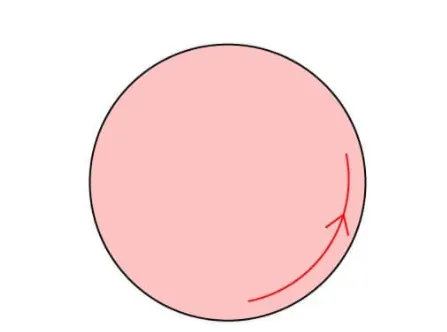
Particles with greater inertia will be less affected by the vortex and will continue travelling in a straight line. This straight-line trajectory causes the high inertia particles to move out of the gas stream and impact with the cyclone separator body. These particles then fall to the base of the cyclone separator and out of the reject port. In this way, entrained particles of a certain size can be separated from the gas stream.
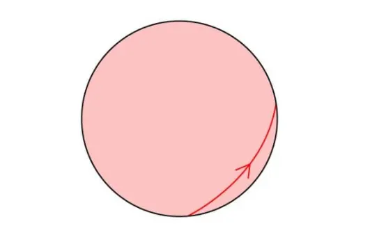
Another way to think of this process is to think of higher density particles colliding with the cyclone body whilst less dense particles are retained within the gas stream. This is not strictly true though as both the density and shape of the particle will affect its ability to be separated from the gas stream.
Particles discharged through the reject port are usually either recycled (off or on-site) or, disposed of.
Factors Affecting Efficiency:
- Particle density
- Particle size
- Volumetric flow rate
- Pressure drops
- Cone length
- Body length
- The ratio of accepting port to body diameter
- The smoothness of the cyclone’s internal surfaces
Advantages:
- Cheap to purchase.
- Low maintenance.
- Suitable for high temperatures.
- Suitable for liquid mists.
- Do not require much space
Disadvantages:
- Increased operating costs associated with the pressure drop (assuming large pressure drop).
- Inefficient when handling small/fine particles.
- Not suitable for ‘sticky’ substances.
Applications:
Saw mill:
Sawmills generate a lot of dust which must be extracted from the mill. Dust is drawn into the main extraction system by a negative pressure created by a fan -usually a centrifugal fan-. The dust-laden air then passes through a cyclone separator where most of the wood dust is separated from the air stream; the clean air is then discharged directly to ambient air whilst the wood dust is recycled or disposed of.
Vacuum cleaner:
An electric motor drives a fan which draws air and particles into the vacuum cleaner body. There are few parts to maintain and the vacuum has the added advantage of having no bags that need to be replaced.
Empirical models used to calculate the cyclone separator efficiency:
- IOZIA AND LEITH MODEL
Iozia and Leith (1990) logistic model is a modified version of Barth (1956) model which is developed based on force balance. The model assumes that a particle carried by the vortex endures the influence of two forces: a centrifugal force, Z, and flow resistance, W. Core length, zc, and core diameter, dc, are given as
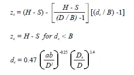
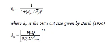
The addition made by Iozia and Leith on the original Barth(1956) model is the core length zc and slope parameter b expression which is derived based on the statistical analysis of experimental data of cyclone with D = 0.25 m. The collection efficiency hi of particle diameter dpi can be calculated from
2. LI AND WANG MODEL
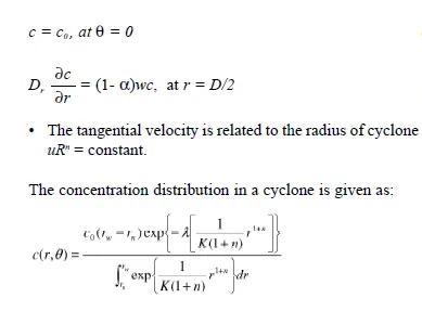
The Li and Wang (1989) model include particle bounce or re-entrainment and turbulent diffusion at the cyclone wall. A two-dimensional analytical expression of particle distribution in the cyclone is obtained. Li and Wang model was developed based on the following assumptions:
- The radial particle velocity and the radial concentration profile are not constant, for uncollected particles within the cyclones.
- Boundary conditions with the consideration of turbulent diffusion coefficient and particle bounce re-entrainment on the cyclone wall are:
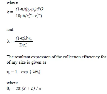
3. KOCH AND LICHT MODEL
Koch and Licht (1977) collection theory recognized the inherently turbulent nature of cyclones and the distribution of gas residence times within the cyclone. Koch and Licht describe particle motion in the entry and collection regions with the additional following assumptions:
- The tangential velocity of a particle is equal to the tangential velocity of the gas flow, i.e. there is no slip in the tangential
direction between the particle and the gas.
- The tangential velocity is related to the radius of cyclone by uRn = constant
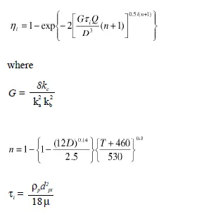
4. LAPPLE MODEL
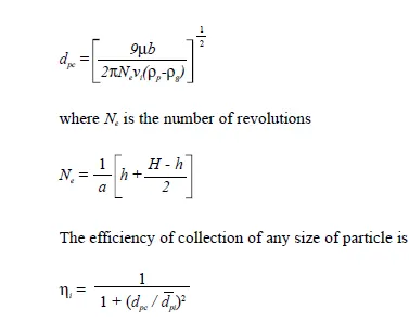
Lapple (1951) model was developed based on force balance without considering the flow resistance. Lapple assumed that a particle entering the cyclone is evenly distributed across the inlet opening. The particle that travels from inlet half-width to the wall in the cyclone is collected with 50% efficiency. The semi-empirical relationship developed by Lapple (1951) to calculate a 50% cut diameter, dpc, is
Discrete Phase Modelling(DPM):
To carry out our analysis we will use Discrete Phase Modelling. It is employed when we want to represent solid particles in gas or liquid, or to represent liquid droplets in gas or to represent bubbles in the liquid.
Discrete Phase Model is especially used for spray simulations or more general suspended particle trajectory simulations. This model is based on the Euler-LaGrange method.
There are two different phases in DPM:
- Continues Phase: Continues phase consists of the fluid that is flowing within the fluid volume
- Discrete Phase:
- Consists of smaller particles interacting with the continuous phase
- Can change momentum, mass, the energy within the fluid phase or continuous phase in our case
Two ways of carrying out DPM:
Coupled flow:
In coupled flow, the discrete phase will influence the flow of the continues phase.
Uncoupled flow:
The discrete phase will not have any interaction with the continues phase.
But since the size of the particles injected into the cyclone separator is very small, usage of both the type of flow should not matter much.
The calculation process followed in the DPM:
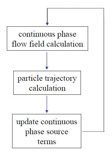
Coupling between continuous and Discrete phase:
- One-way coupling
- Two-way coupling
Tracking Parameters:
- Maximum number of steps
- Length scale
- Step length factor
Boundary condition types:
Reflect:
The particle rebounds the off the boundary in question with a change in its momentum as defined by the coefficient of restitution.
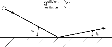
"Reflect'' Boundary Condition for the Discrete Phase
Trap:
The trajectory calculations are terminated and the fate of the particle is recorded as "trapped''. In the case of evaporating droplets, their entire mass instantaneously passes into the vapour phase and enters the cell adjacent to the boundary. In the case of combusting particles, the remaining volatile mass is passed into the vapour phase.
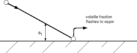
"Trap'' Boundary Condition for the Discrete Phase
Escape:
The particle is reported as having "escaped'' when it encounters the boundary in question. Trajectory calculations are terminated.

"Escape'' Boundary Condition for the Discrete Phase
Wall-jet
The wall-jet type boundary condition is appropriate for high-temperature walls where no significant liquid film is formed, and in high-Weber-number impacts where the spray acts as a jet. The model is not appropriate for regimes where the film is important (e.g., port fuel injection in SI engines, rainwater runoff, etc.).
Wall-film
This boundary condition consists of four regimes: stick, rebound, spread, and splash, which are based on the impact of energy and wall temperature.
Interior
This boundary condition means that the particles will pass through the internal boundary. This option is available only for internal boundary zones, such as a radiator or a porous jump.
It is also possible to use a user-defined function to compute the behaviour of the particles at a physical boundary.
Geometry:
The 3D model of the cyclone separator was imported to SpaceClaim. Extraction of the fluid volume was done by selecting the inner edges at inlet and two outlets using volume extraction method.
3D Model:
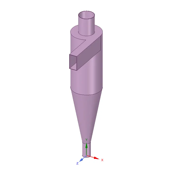
Edge selection for volume extraction:
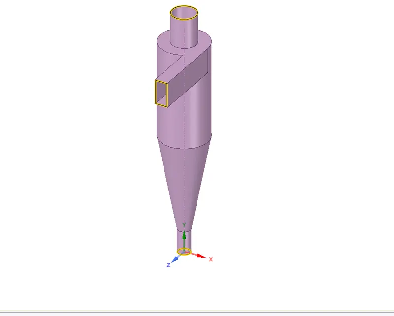
Fluid volume:
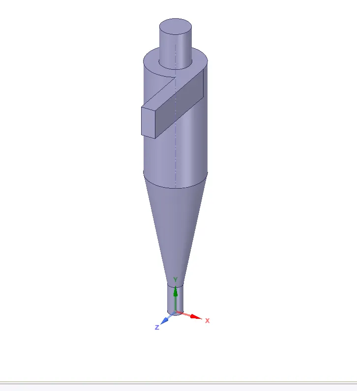
Meshing:
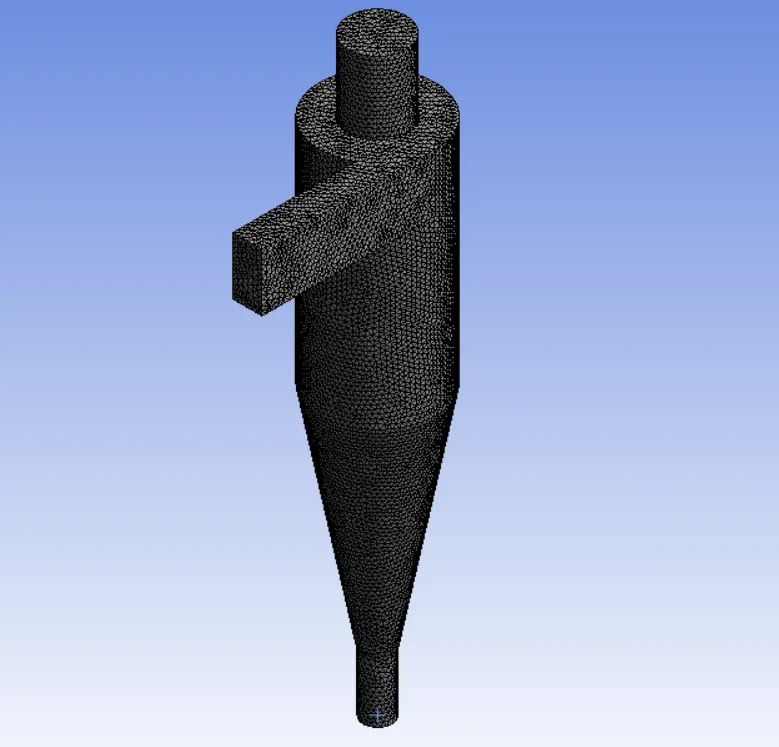
Triangle meshing method was assigned. Element size of the mesh was 8mm. The naming of inlet and outlets were also done.
Number of nodes = 37383
Number of elements = 186914
Mesh metric:
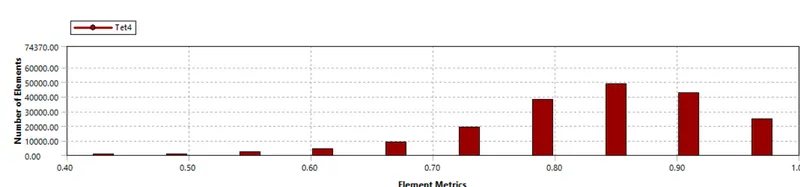
The mesh metric that identifies the elements according to their quality was employed and it can be seen that the elements of lowest quality are minimal, most of the elements have very high quality in the range of 0.8-1.
Setup:
Solver Type: Pressure based
Time: Steady-state
Gravitational acceleration (Y )= -9.81
Models:
Viscous model: K-epsilon -RNG -Swirl dominated flow with standard wall functions;
Discrete phase:
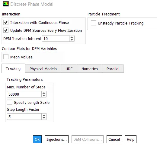
Enable Interaction with continuous phase: This is done in order to enable the coupled flow.
Enable update DPM source every flow iteration: Enabling this option gives chance to calculate the particle source term at every flow iteration.
DPM iteration interval: Allows us to control the frequency at which the particle is tracked. So, if we specify a higher interval it will be computationally less heavy. We go with the default value of 10.
Tracking parameters: Maximum number of steps = 50000, Maximum number of steps is the number of time steps that are used to compute a single particle trajectory. In case fluid exceeds this number of steps it will automatically cancel the reporting of the trajectory. If we consider a case wherein a particle trapped in a recirculation region, by specifying the number of the maximum number of steps we can stop fluent from tracking that particular particle infinitely. For steady-state case 50000 is the maximum number of steps given by default. When we know that the particle is not trapped, then we can specify a higher number of steps in order to evaluate if it’s coming out of the recirculation region.
Step length factor = 5
Both step length factor and specify length scale options are used to control the time step size.
If we take specify length scale option the time step is calculated by dividing the length scale by the sum of the velocity of the discrete particle and velocity of the continuous phase. Ideally, we would go for a lesser value of the length scale in order to increase the accuracy of the trajectory, this means that the lesser value of the time step size will increase the accuracy of the trajectory.
Step length factor is also used to control the time step size. While calculating the time step using a step length factor, the larger the step length factor we will have smaller time step size and the accuracy of the trajectory will decrease.
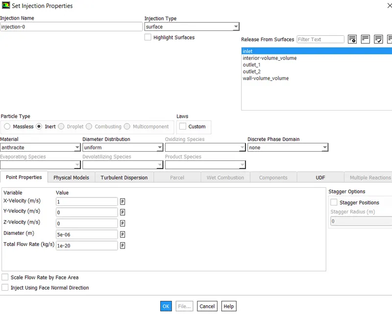
Particle type: Inert
Material: Anthracite
Injection type: Surface injection
Release from a surface: Inlet
X velocity and the particle diameter is given according to the different cases we consider for simulating.
Boundary condition:
Inlet: Velocity inlet
Velocity magnitude: 3m/s for case 1 and for the case two velocities will vary between 1m/s to 5 m/s.
DPM: Reflect
Outlet 1(Top): Pressure outlet
Gauge Pressure: 0 Pa
DPM: Escape
Outlet 2(Bottom): Pressure outlet
Gauge pressure: 0 Pa
DPM: Trap
Solution Method:
Pressure-velocity coupling scheme: Simple
Spatial discretization:
Gradient: Least square cell-based
Pressure: Second order
Momentum: Second order upwind
Turbulent kinetic energy: Second order upwind
Initialization:
Standard initialization – compute from the inlet
Run calculation.
Simulation Results:
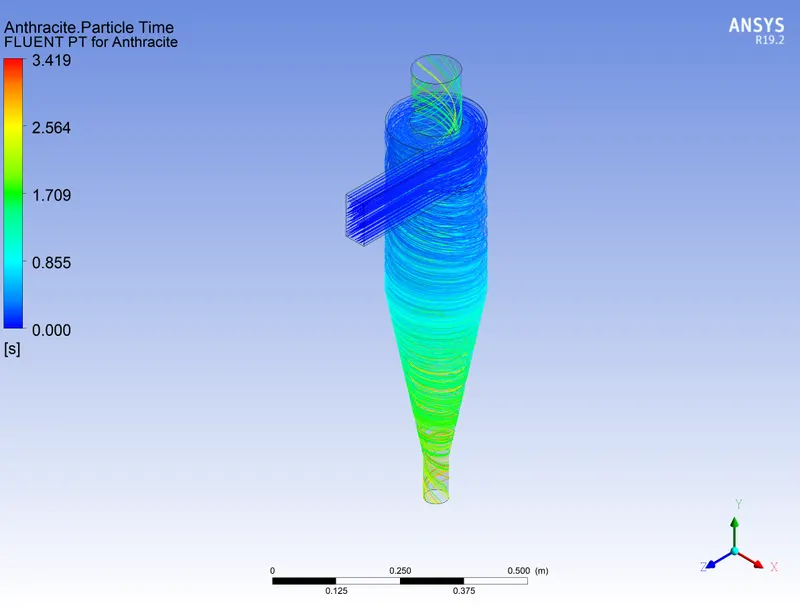
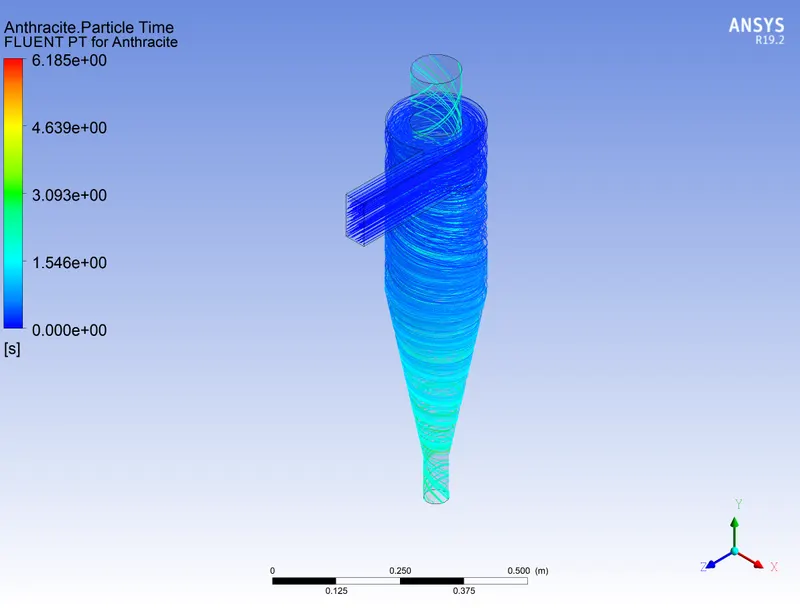
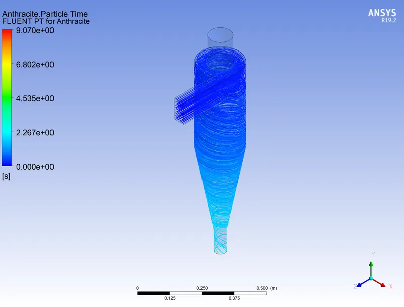
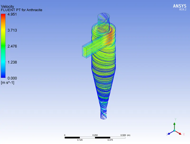
Case 1: Varying the particle diameter and calculating the separation efficiency in each case. Particle and Flow velocity= 3m/sec.
|
Particle diameter=1e-06m
|
Particle diameter=3e-06m
|
Particle diameter=5e-06m
|
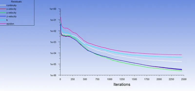
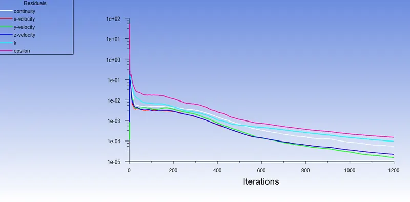
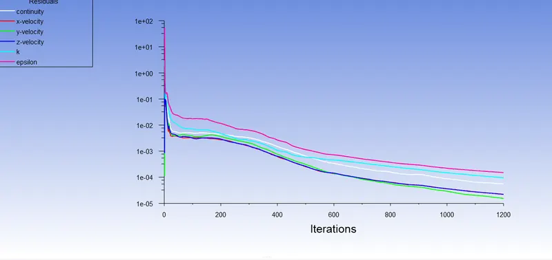
For Particle diameter=1e-06m

For Particle diameter=3e-06m

For Particle diameter=5e-06m

We know,

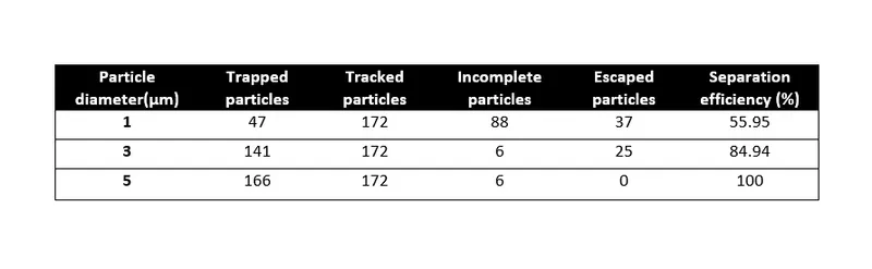
Separation efficiency @Dia = 1e-06m = (47)÷(172-88)=0.5595
Separation efficiency @Dia = 3e-06m = (141)÷(172-6)=0.8494
Separation efficiency @Dia = 5e-06m = (166)÷(172-6)= 1.00
The values of the separation efficiency are shown in the table
Result Table:
Each Particle resident time:
 |
 |
 |
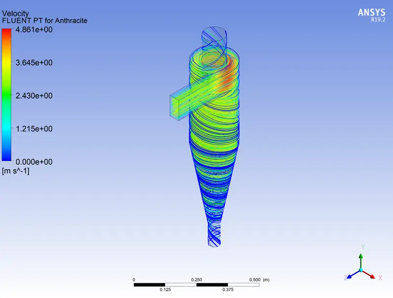
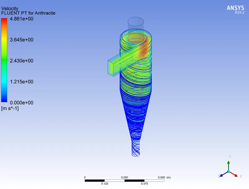
Velocity contour:
 |
 |
 |
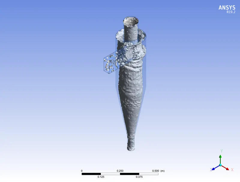
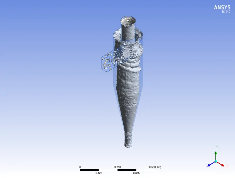
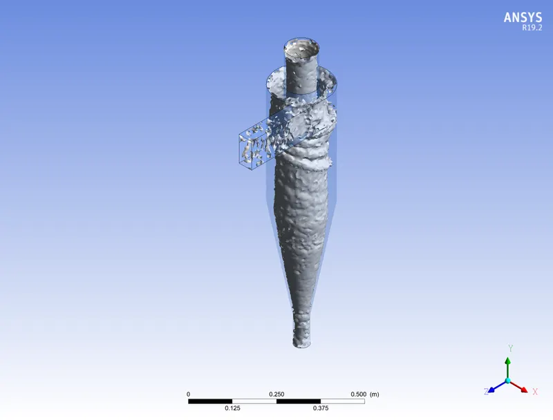
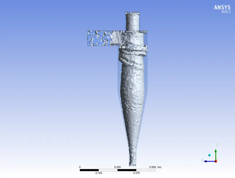
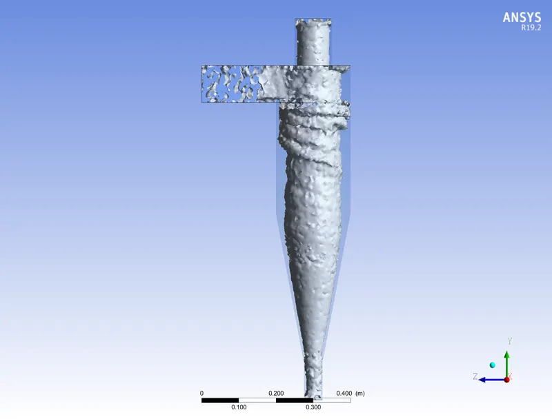
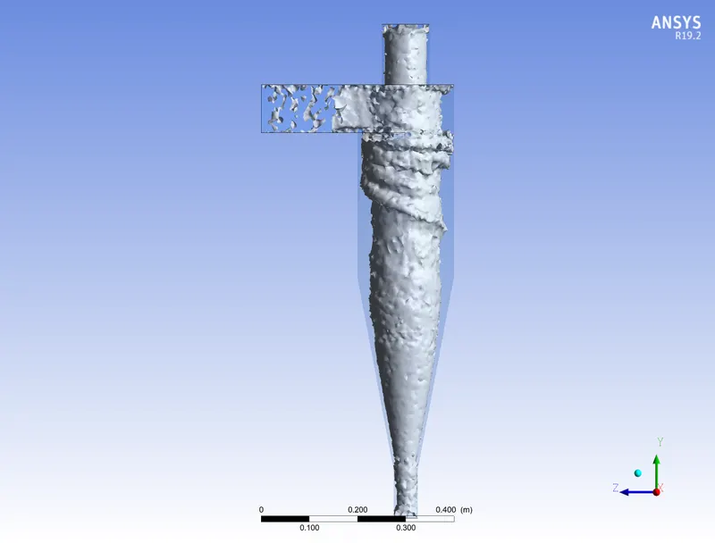
Vortex at 0.025 swirl strength:
 |
 |
 |
 |
 |
|
Animations:
Calculation:
Mass flow rate unit- Kg/s
| Particle size * e-06m | Mass flow rate at Inlet | Mass flow rate at outlet 1 (Top) | Mass flow rate at outlet 2 (Bottom) |
| 1 | 0.018375 | -0.0148 | -0.003575 |
| 3 | 0.018375 | -0.014928 | -0.003446 |
| 5 | 0.018375 | -0.014928 | -0.003446 |
Case 2:
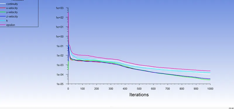
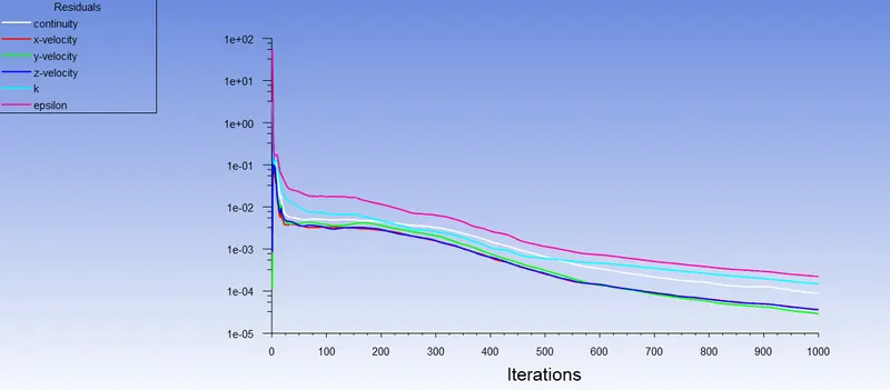
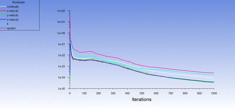
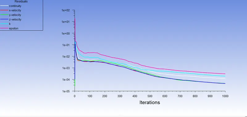
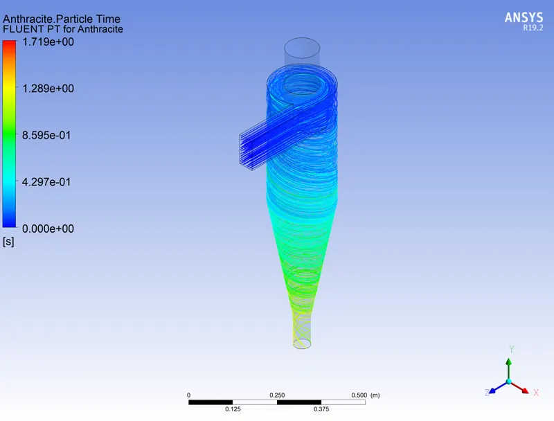
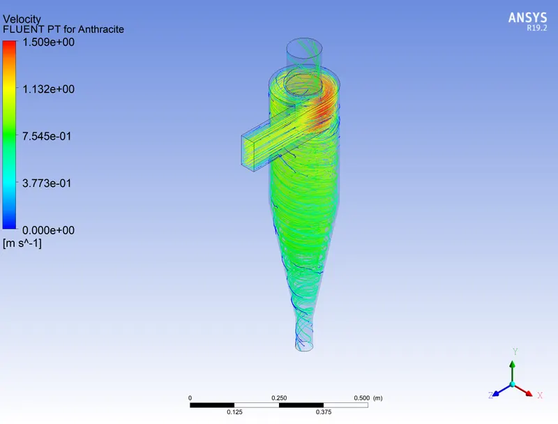
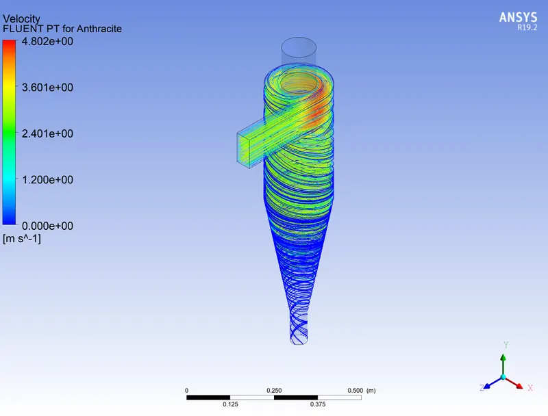
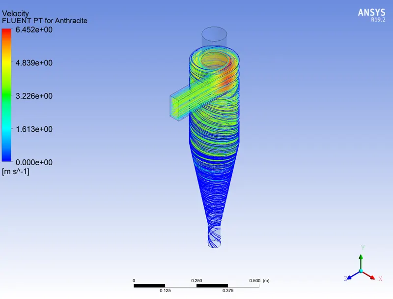
Varying the particle velocity (keeping flow velocity same as particle velocity) and calculating the separation efficiency and pressure drop in each case. Particle diameter size used 5 μm.
|
Particle velocity= 1m/s
|
Particle velocity=3m/s
|
Particle velocity=4m/s
|
|
|
Particle velocity= 5m/s
|
Pressure plot:
|
Particle velocity= 1m/s
|
Particle velocity= 3m/s
|
Particle velocity= 4m/s
|
|
|
Particle velocity= 5m/s
|
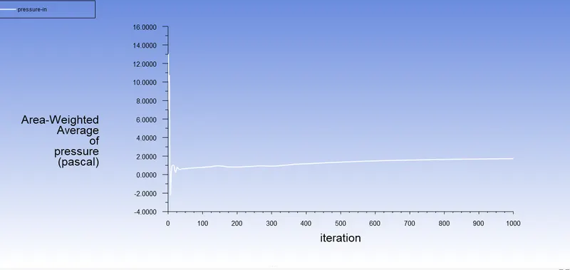
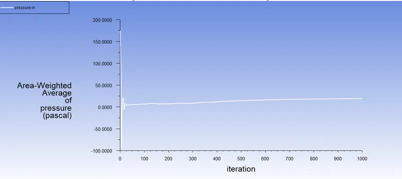
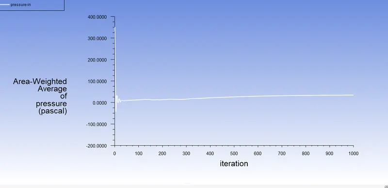
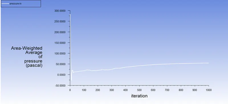
For Particle velocity= 1m/s

For Particle velocity= 3m/s

For Particle velocity= 4m/s

For Particle velocity= 5m/s

We know,
Separation efficiency @velocity= 1m/s = (18)÷(172-144)=0.6428
Separation efficiency @velocity= 3m/s = (163)÷(172-9)= 1.00
Separation efficiency @velocity= 4m/s = (172)÷(172-0)= 1.00
Separation efficiency @velocity= 1m/s = (172)÷(172-0)= 1.00
The values of the separation efficiency are shown in the table
Result Table:
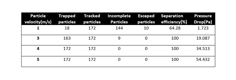
Separation efficiency might be same at particle velocity 3m/s and 4m/s but we can see there are incomplete particles at particle velocity 3m/s which reduce to zero at 4m/s particle velocity.
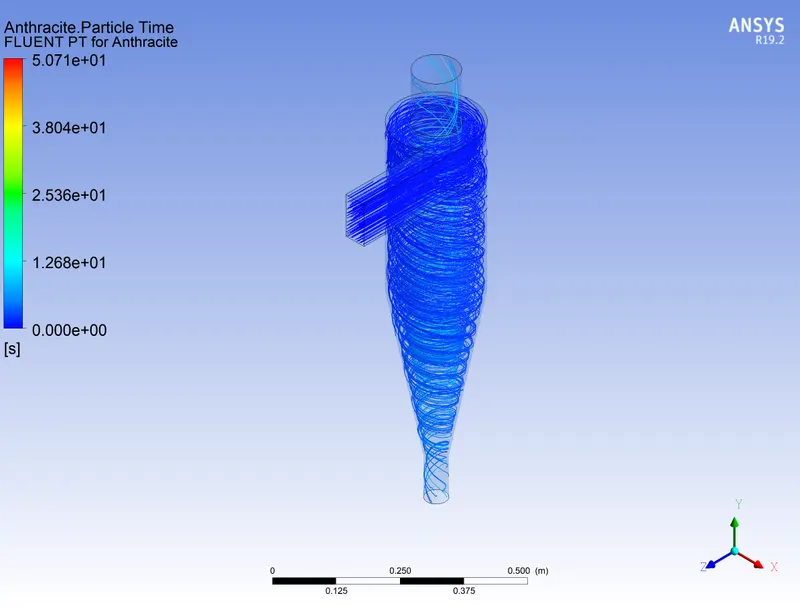
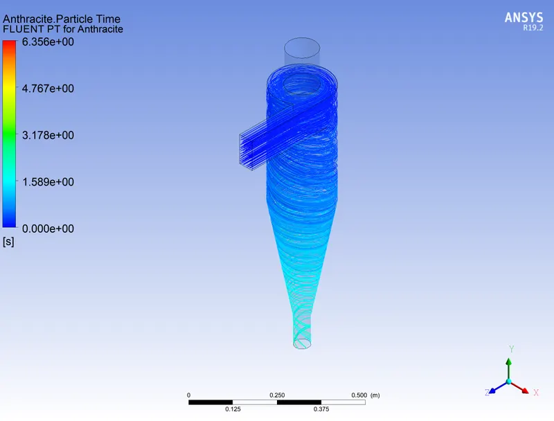
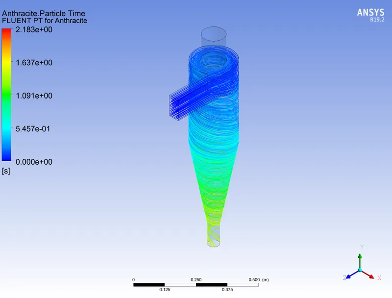
Each Particle resident time:
 |
 |
 |
 |
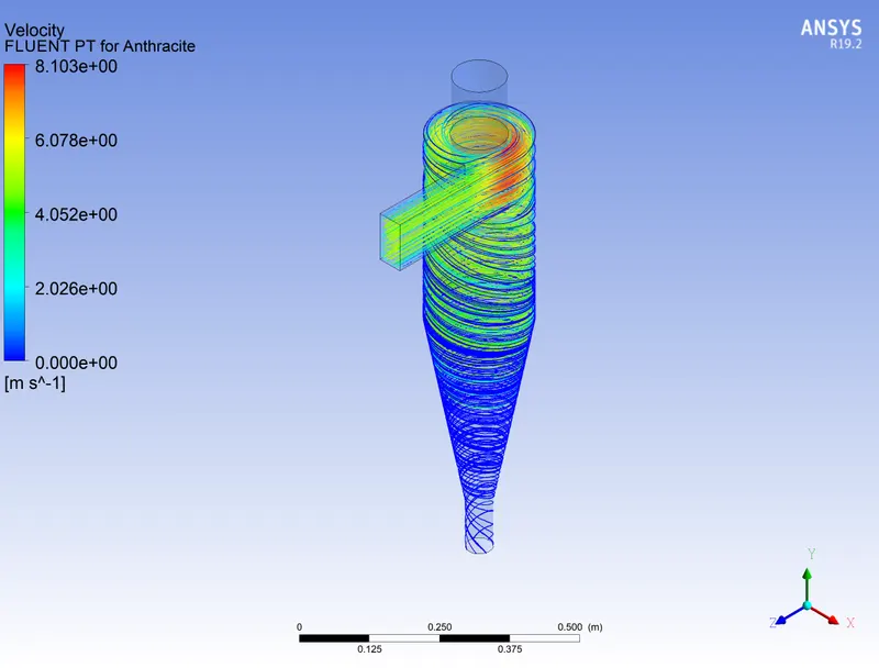
Velocity contour:
 |
 |
 |
 |
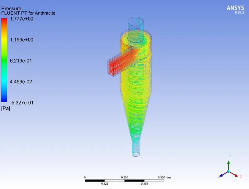
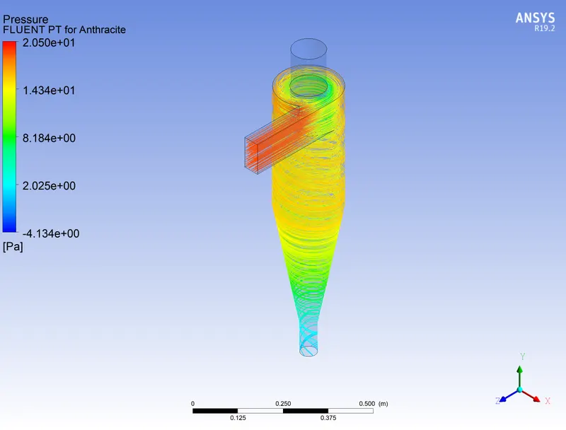
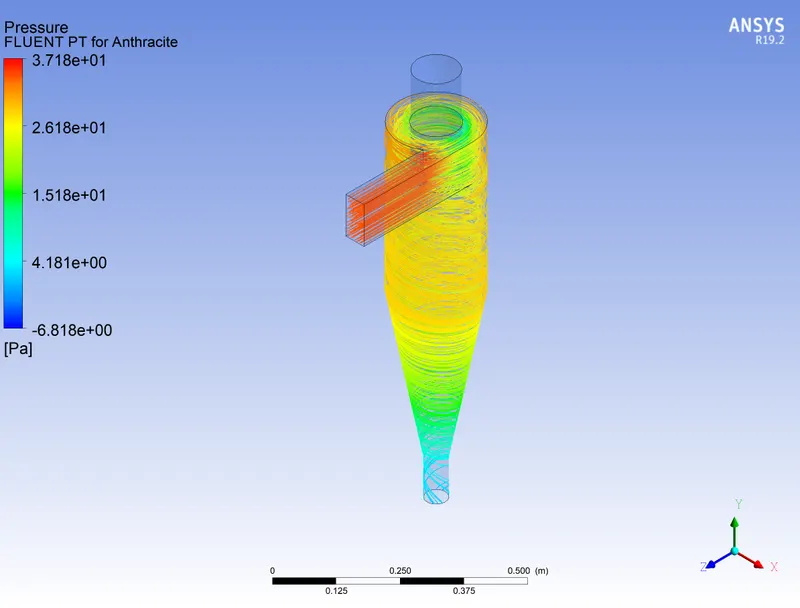
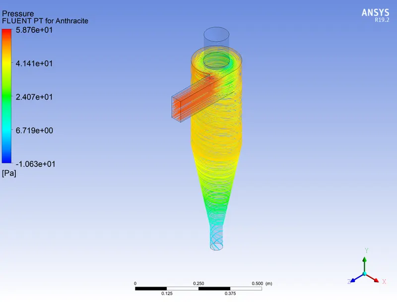
Pressure contour:
 |
 |
 |
 |
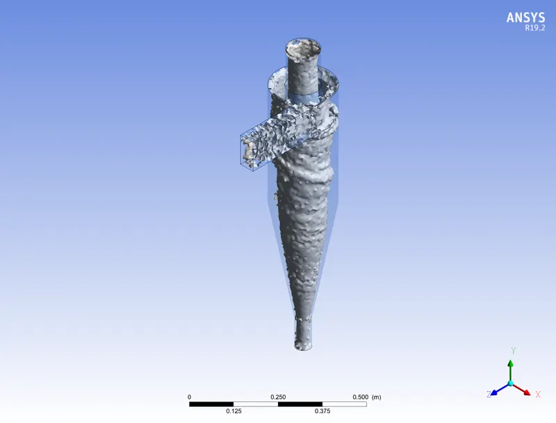
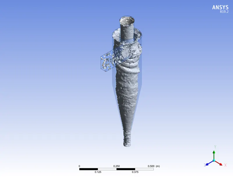
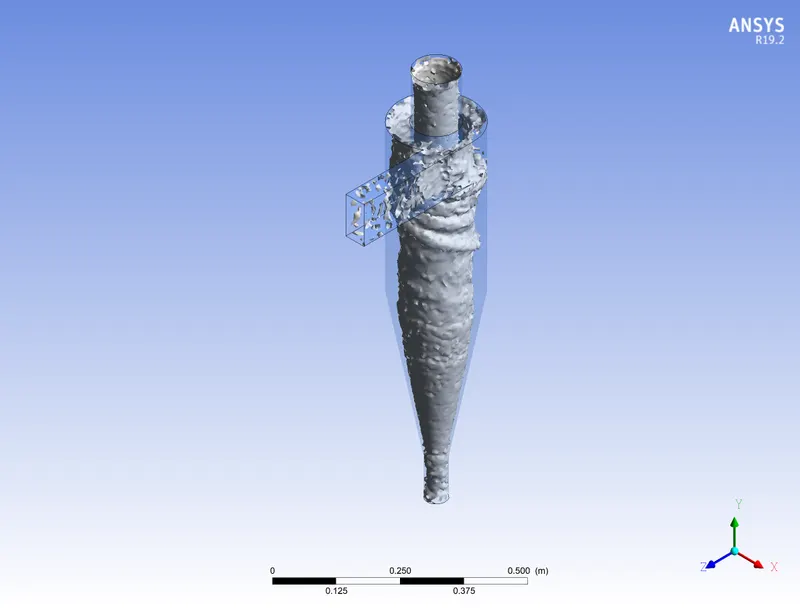
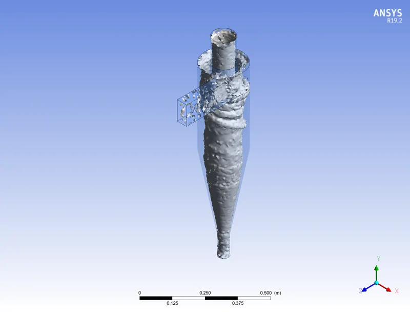
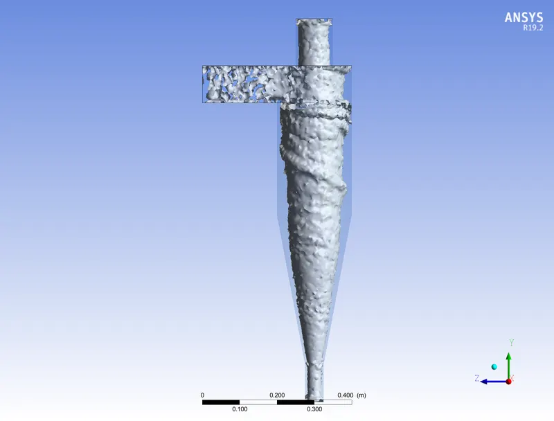
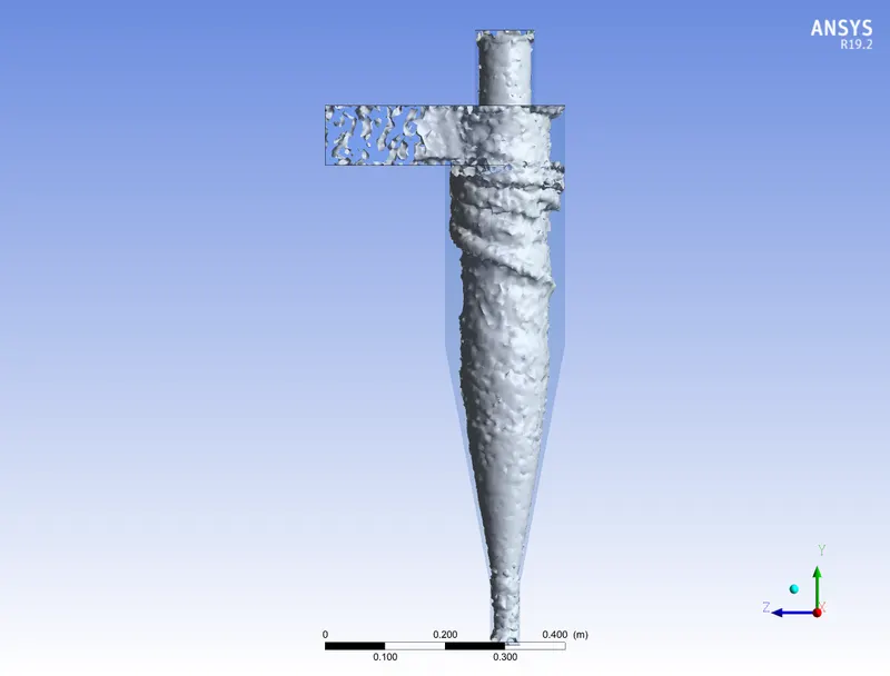
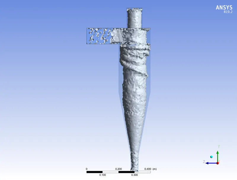
Vortex at 0.025 swirl strength:
 |
 |
 |
 |
 |
 |
 |
 |
Animations:
Calculation:
Mass flow rate unit- Kg/s
| Particle velocity(m/s) | Mass flow rate at Inlet | Mass flow rate at outlet 1 (Top) | Mass flow rate at outlet 2 (Bottom) |
| 1 | 0.006125 | -0.004954 | -0.0011703 |
| 3 | 0.018375 | -0.015063 | -0.0033103 |
| 4 | 0.0245 | -0.020232 | -0.004264 |
| 5 | 0.030625 | -0.02546 | -0.005163 |
Conclusion:
For case 1,
As the particle size increases, the number of trapped particles increases and we can also see the number of incomplete and escaped particles decreasing with an increase in the particle size and for constant particle velocity. A reduction in particle size will give a corresponding reduction in efficiency. This is because, as the size of the particle increases it becomes easier for the cyclone to separate the larger particles.
So, Particle size is a large design consideration affecting a separator’s efficiency. Larger particles can be more easily separated than smaller particles.
For case 2,
Here the velocity of the particle was varied keeping particle diameter as constant. From the obtained result we can say that with the increase in the particle/air velocity the number of trapped particles increases this is happening because the number of incomplete and escaped particle is decreasing. So as per the result obtained the separation efficiency of the cyclone increases even with the increase in the particle velocity. Velocity has a greater impact as compared to the diameter of the particle.
While carrying out the experiment it was also observed that a greater number of the particles escaped out of the outlet 2(i.e., bottom outlet) and few particles even escaped through the outlet 1(i.e., top outlet). We wanted a greater number of particles to be sedimented in outlet 2 and we were able to achieve it.
Even the pressure drop increases with an increase in velocity. The pressure drop can be thought of as the amount of energy required to move the gas through the separator, alternatively, it can be thought of as the amount of resistance the cyclone separator adds to the system flow. The pressure drop is a product of the gas flow rate, gas density and cyclone geometry.
So, from the results, we can conclude that the factors affecting the efficiency are particle size, volumetric flow rate, pressure drop. Even geometry of the cyclone separator greatly impacts the efficiency this can be checked by simulating for varying diameter cyclone separator.