Week 8 - Simulating Cyclone separator with Discrete Phase Modelling
AIM: To perform analysis on Cyclone Separator and calculate the separation efficiency and pressure drop.
OBJECTIVE:
- To write a few words about any four empirical models used to calculate separator efficiency.
- To perform an analysis on a given cyclone separator model by varying the particle diameter from 1 `mum` to 5 `mum` and calculate the separation efficiency in each case. Discuss the results. [Use both the velocity's as 3m/sec.]
- To perform an analysis on a given cyclone separator model by varying the particle velocity from 1 m/sec to 5 m/sec and calculate the separation efficiency and pressure drop in each case. Discuss the results. [Use particle diameter size as 5 `mum` for all cases and keep flow velocity same as particle velocity].
THEORETICAL EXPLANATION:
Cyclone Separator:
There are two main designs of Cyclone separator, Gas cyclone, and Hydro cyclone. Gas cyclones are used to remove entrained particles from a gas stream. Hydro cyclones are used for separating fluids of different densities.
Cyclone separators can be installed as single units or in multiple known as multi cyclones. Separators can be installed with horizontal or vertical orientation. It is also possible to install cyclones in series or parallel.
Gas Cyclone Separator
Gas cyclone separators are grouped into two main categories, Reverse flow and Axial flow. Reverse flow cyclone separators are cone-shaped, gas enters at the top of the separator body, flows downwards then flows back upwards, and is discharged. For Axial flow cyclone separators, gas enters at one end and is discharged at the opposite end. The axial flow design is not as common as the reverse flow design.
The project will focus on the reverse flow gas cyclone separator because this type of separator is the most commonly used today.
Components and Design
A Reverse flow cyclone separator is an industrial assembly with no moving parts and a simple design. The main cylindrical part of the cyclone separator is known as the body or barrel, the gradually narrowing conical section is known as the cone. Untreated gas enters tangentially through the inlet at the side of the separator. Entrained particles within the gas stream are separated from the gas stream and discharged through the reject port of the base of the separator. Clean gas exits through the accept port at the top of the separator.
Working of the Cyclone Separator
Gas containing entrained particles enters at high velocity through the tangential inlet at the top of the cyclone. The gas flows into the cyclone body at a tangent and begins to flow in a circular downward flowing spiral towards the lower reject port. This downward flowing spiral is referred to as a spiral vortex. The cone diameter gradually decreases which causes the gas velocity to increase the outer vortex creates an additional inner vortex closer to the center of the separator body and this inner vortex flows spirally upwards toward the accept port.
Particles with more inertia will impact the side of the cyclone, whilst particles with lower inertia will remain within the gas stream. Inertia can be thought of as a particle's ability to continue traveling in a straight line, even when external forces are applied.
When an external force is applied such as by the cyclonic vortex, particles with low inertia will not continue to travel in a straight line. They will instead travel sparely as they are swept along by the gas stream. Particles with great inertia will be less affected by the vortex and will continue traveling in a straight line. This straight-line trajectory causes the high inertia particles to move out of the gas stream and impacts the cyclone separator body. These particles then fall to the base of the cyclone separator and out of the reject port.
In this way, entrained particles of a certain size can be separated from the gas stream.
Another way to think of this process is to think of higher-density particles colliding with the cyclone body whilst less dense particles are retained within the gas stream. This is not strictly true though as both the density and the shape of the particle will affect its ability to be separated from the gas stream. Particles discharged through the reject port are usually either recycled back into the process or disposed off.
Factors affecting the Efficiency:
There are several factors that can affect the cyclone separator efficiency. These include particle density, particle size, volumetric flow rate, pressure drop, cone length, body length, the ratio of accepting port to body diameter, and even the smoothness of the cyclone's internal surfaces.
We will now discuss the most important design aspects:
Particle Density
Particle density is one of the most deciding factors, affecting the cyclone's ability to remove entrained particles. Dense particles such as various oxides can be separated with a 99% or greater efficiency, irrespective of particle size. Dense particles are easily separated. When the particle density decreases, the efficiency decreases.
Particle Size
Particle size is a large design consideration affecting the separator's efficiency. Larger particles can be more easily separated than smaller particles. Particles smaller than five microns are difficult to separate without using very small separators. Particles exceeding 200 microns can often be separated using other means, such as gravity settling chambers. A reduction in particles size will give a corresponding reduction inefficiency.
Geometry
A separator's geometry greatly impacts the efficiency of the unit. A large diameter cyclone separator will not be able to separate particles as efficiently as a smaller diameter separator. The efficiency of the separator increases as the cone diameter decreases. Thus reducing the cone diameter, enables the removal of finer and finer particles. A small diameter cone will extract much finer particles from a gas stream than the larger diameter cone.
Pressure Drop
All cyclone separators have an associated pressure drop. The pressure drop can be thought of as the amount of energy required to move the gas through the separator. Alternatively, it can be thought of as the amount of resistance the cyclone separator adds to the system flow.
Separator body to accept port diameter ratio
Finally, another way to increase a separator's efficiency is to reduce accept port diameter. This changes to the separator body to accept port diameter ratio and has the effect of only allowing finer particles to leave the separator through the accept port.
Large or Small separator
Small cyclone separators have a higher efficiency rating but the associated pressure drop is high and the volumetric flow rate is low. Gas velocity through a small separator is also very high and this will lead to a higher level of erosion if the gas stream contains abrasive particles.
Large cyclone separators have a lower efficiency rating but the associated pressure drop is low and the volumetric flow rate high. A large cyclone separator is not suitable for removing fine particles from a gas stream.
Advantages and Disadvantages:
There are many advantages associated with cyclone separators some of these include cheap to purchase, low maintenance, suitable for high temperatures, suitable for liquid mist and vapors, do not require much space.
Some disadvantages are associated with cyclone separators but these disadvantages can be reduced in severity if the correct separator is selected for the correct application. Disadvantages may include high operating costs, associated with the pressure drop across the separator, inefficient when handling smaller fine particles, and not being suitable for sticky substances.
CYCLONE EFFICIENCY EMPIRICAL MODELS:
Iozia and Leith Model:
Iozia and Leith's (1990) logistic model is a modified version of Barth's (1956) model which is developed based on force balance. The model assumes that a particle carried by the vortex endures the influence of two forces: a centrifugal force, Z, and flow resistance, W. Core length, zc">zczc, and core diameter, dc">dcdc, is given as
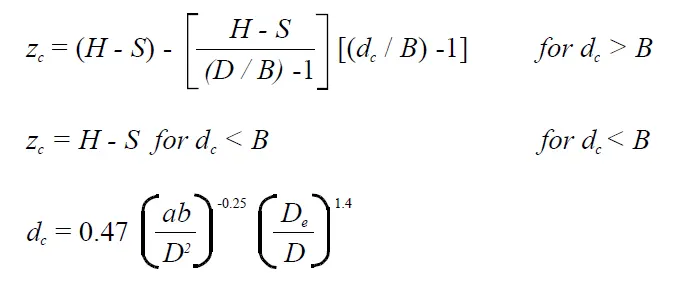
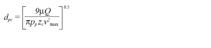
The addition made by Iozia and Leith on the original Barth (1956) model is the core length zc">zczc and slope parameter β">ββ expression which is derived based on the statistical analysis of experimental data of cyclone with D = 0.25 m. The collection efficiency ηi">ηiηi of particle diameter dpi">dpidpi can be calculated from

where dpc">dpcdpc is the 50% cut size by Barth (1956)
Li and Wang Model:
The Li and Wang (1989) model include particle bounce or re-entrainment and turbulent diffusion at the cyclone wall. A two-dimensional analytical expression of particle distribution in the cyclone is obtained. Li and Wang's model was developed based on the following assumptions:
- The radial particle velocity and the radial concentration profile are not constant, for uncollected particles within the cyclones.
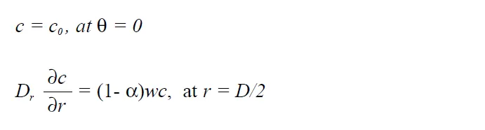
- Boundary conditions with the consideration of turbulent diffusion coefficient and particle bounce re-entrainment on the cyclone wall are:
- The tangential velocity is related to the radius of the cyclone by: uRn">uRnuRn= constant.
The concentration distribution in a cyclone is given as:
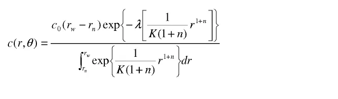
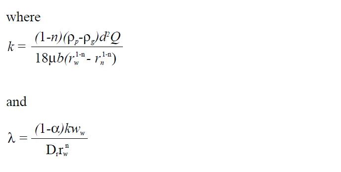
The resultant expression of the collection efficiency for particles of my size is given as
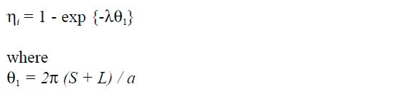
Koch and Licht Model:
Koch and Licht's (1977) collection theory recognized the inherently turbulent nature of cyclones and the distribution of gas residence times within the cyclone. Koch and Licht describe particle motion in the entry and collection regions with the additional following assumptions:
- The tangential velocity of a particle is equal to the tangential velocity of the gas, i.e. there is no slip in the tangential direction between the particle and the gas.
- The tangential velocity is related to the radius of the cyclone by: uRn">uRnuRn= constant.
A force balance and an equation on the particles collection yields the grade efficiency ηi">ηiηi.
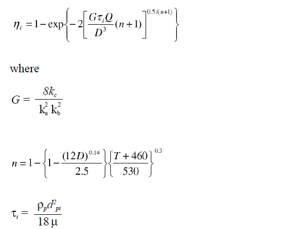
G is a factor related to the configuration of the cyclone, n is related to the vortex and τ">ττ is the relaxation term.
Lapple Model:
Lapple's (1951) model was developed based on force balance without consideration the flow resistance. Lapple assumed that a particle entering the cyclone is evenly distributed across the inlet opening. The particle that travels from the inlet half-width to the wall in the cyclone is collected with 50% efficiency. The semi-empirical relationship developed by Lapple (1951) to calculate a 50% cut diameter, dpc">dpcdpc, is
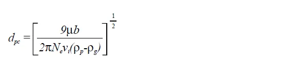
where Ne">NeNe is the number of revolutions

The efficiency of collection of any size of the particle is given by

PROCEDURE:
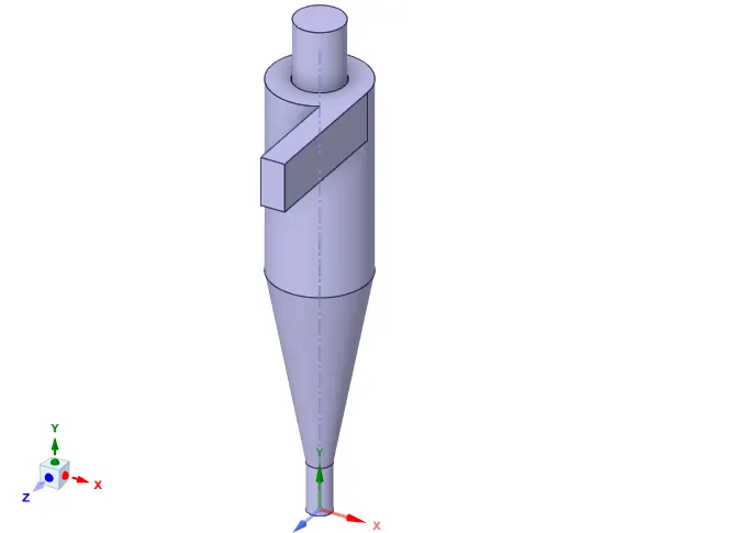
*Import the Geometry in Fluent Spaceclaim, named as Cyclone Separator. stp.Then Extract the Fluid Volume by selecting the inner edges at the Inlet and Outlets of the geometry. After that Hide the Geometry and Suppress it for Physics.
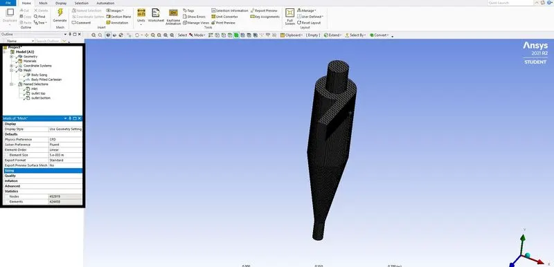
*The meshing is done on the model for a element size of 5 mm with method of cartesian and body sizing is done by selecting the entire model.Name selection is done for the inlet and the outlets.
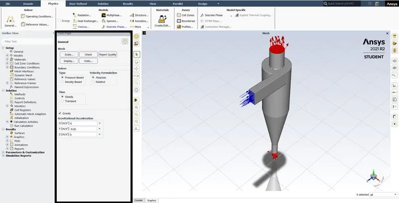
*The setup is started for transient and gravity of y -9.81.
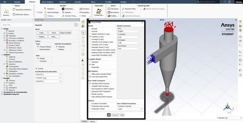
*The turbulent model is used with K epsilon model with RNG and Swirl Dominated wall.
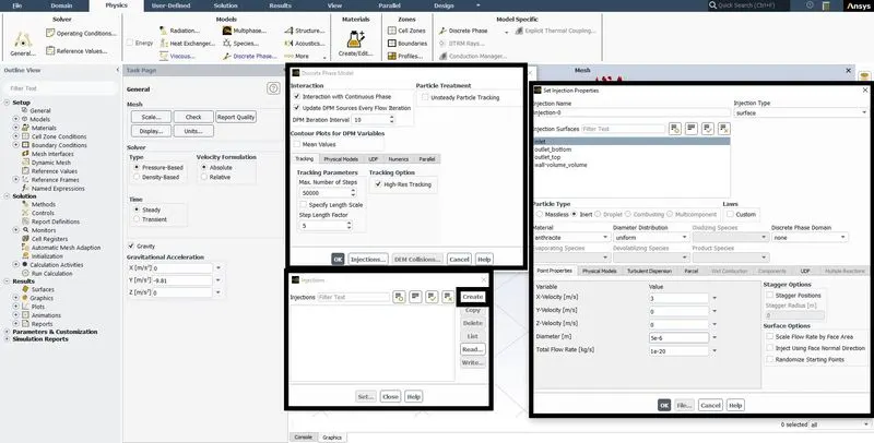
*The multiphase is been turned on to initiate injections and Injection surface and velocity and diameter is been specified.
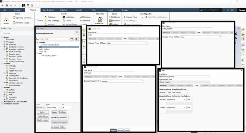
*Boundary Conditions are applied on the inlet with velocity value, outlet with pressure at zero, and the wall with No-slip conditions.Discrete phase Boundary Condition is done as per as recommended type.
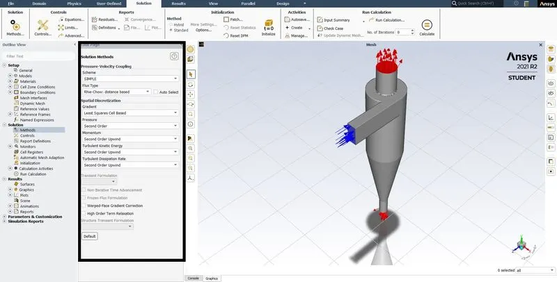
*The solution method is initialed for simple with second order upwind type for suitable parameters.
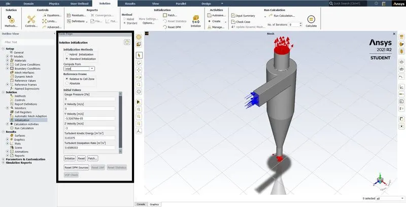
*Initazation of the solution is done for standard and the value is computed form the input parameters.
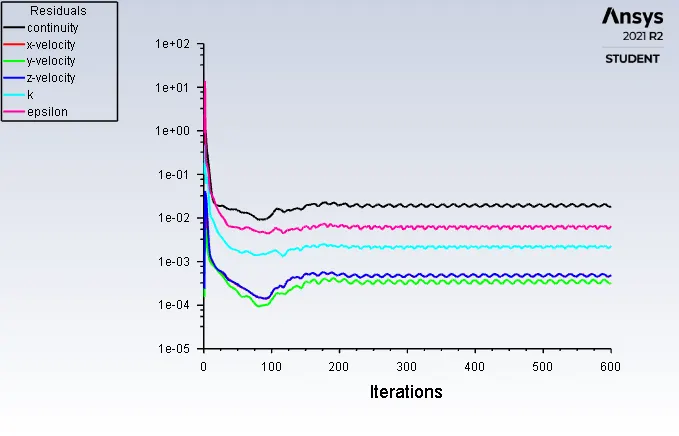
*After the running the simulation for 600 iteration and the solution data is exported for CFD Post for the arthracite particle time.
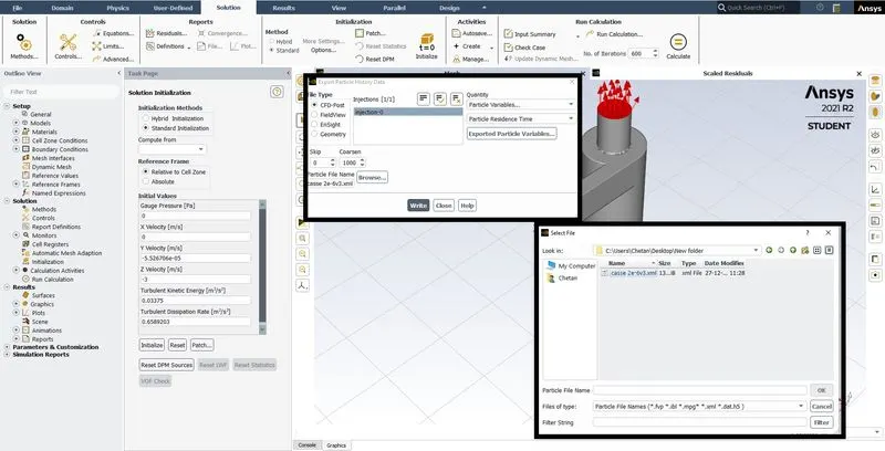
CASE 1 (CONSTANT VELOCITY CASE V= 3 m/s)
Case: 1 A
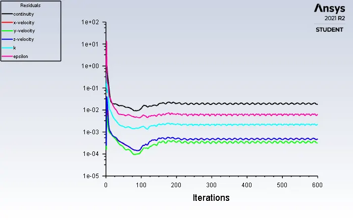
Residuals:-
Particle Resident Time:-
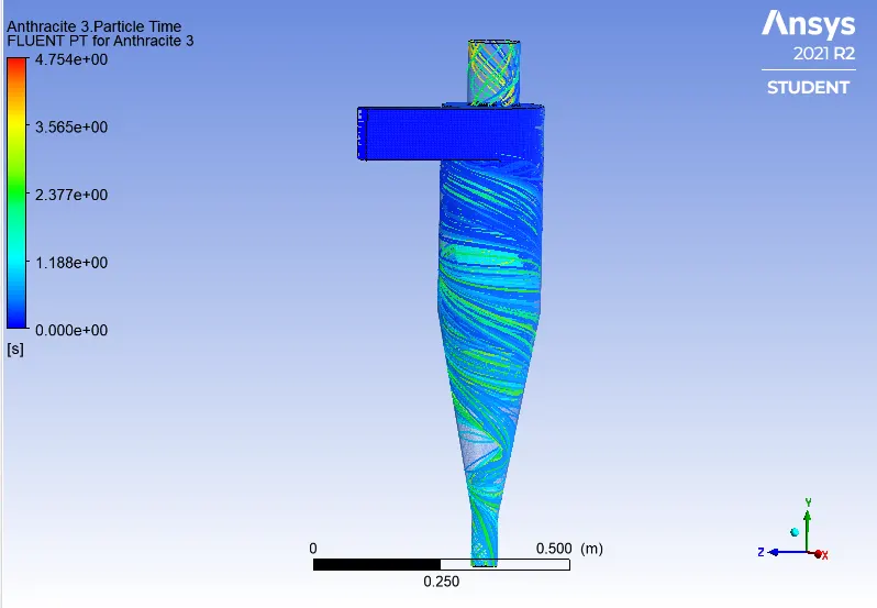
Separation Efficiency = (No. of Particles Trapped)/ (No. of Particles Tracked)
Separation Efficiency = (211/378)*100
Separation Efficiency = 55.820%
Case: 1 B
Residuals:-
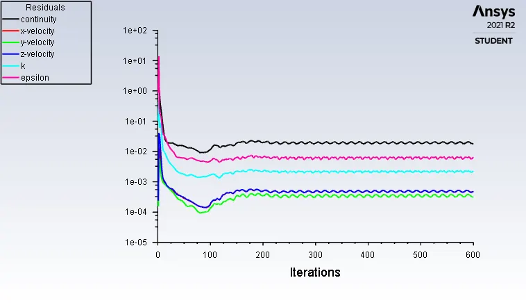
Particle Resident Time:-
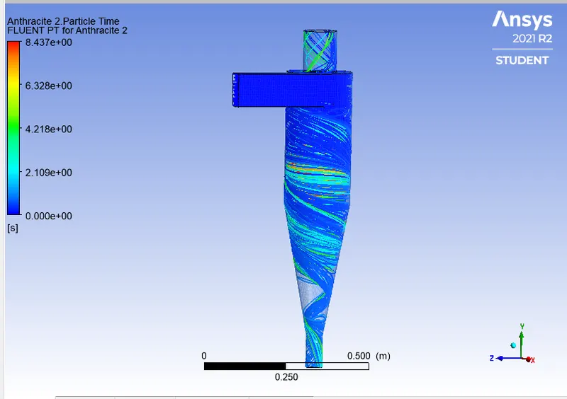
Separation Efficiency = (No. of Particles Trapped)/ (No. of Particles Tracked)
Separation Efficiency = (228/378)*100
Separation Efficiency = 60.317%
Case: 1 C
Residuals:-
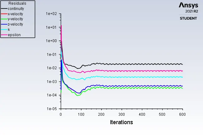
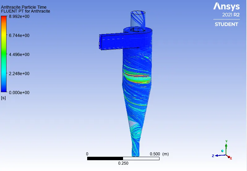
Separation Efficiency = (No. of Particles Trapped)/ (No. of Particles Tracked)
Separation Efficiency = (319/378)*100
Separation Efficiency = 84.391%
CASE 2
Case: 2 A
Residuals:-
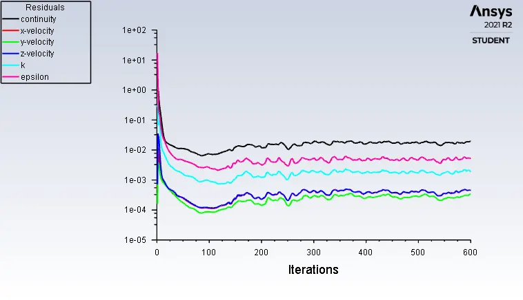
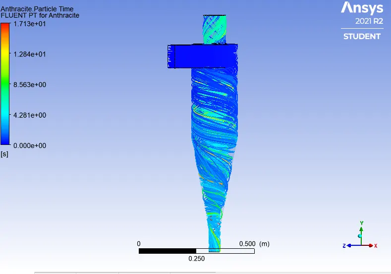
Particle Resident Time:-
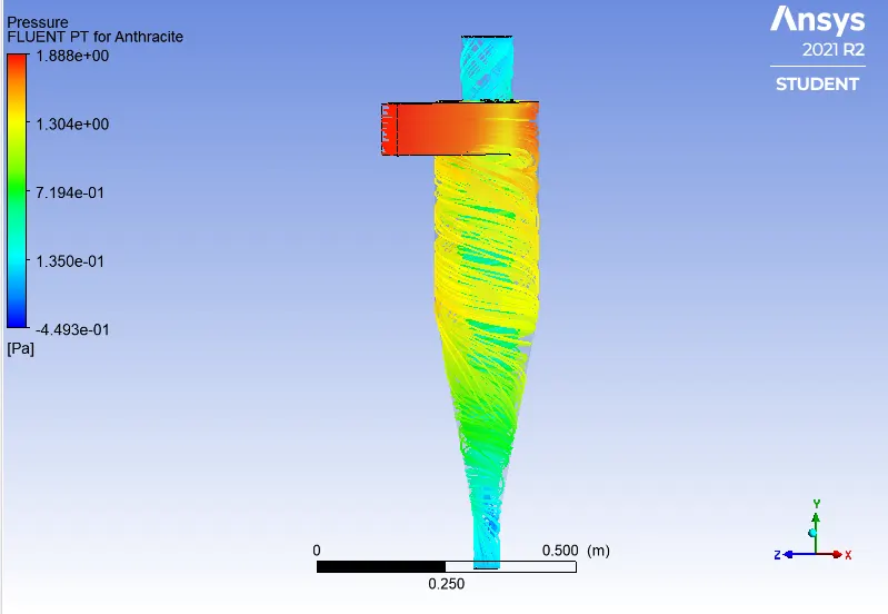
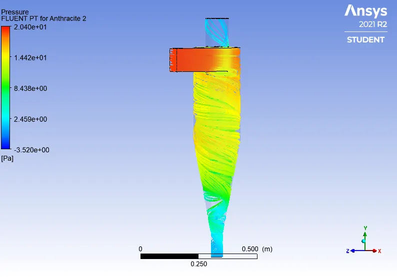
Pressure:-
Separation Efficiency = (No. of Particles Trapped)/ (No. of Particles Tracked)
Separation Efficiency = (320/378)*100
Separation Efficiency = 84.65%
Pressure drop = Pressure at Inlet - Pressure at Oulet
Pressure Drop = 1.8489 - 0.00063
Pressure Drop =1.8482 pa
Case:2 B
Residuals:-
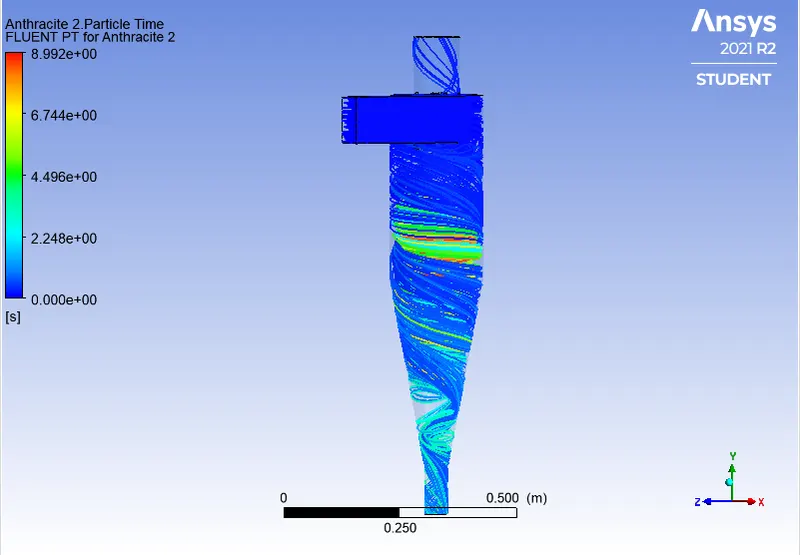
Particle Resident time:-
Pressure:-
Separation Efficiency = (No. of Particles Trapped)/ (No. of Particles Tracked)
Separation Efficiency = (319/378)*100
Separation Efficiency = 84.391%
Pressure drop = Pressure at Inlet - Pressure at Oulet
Pressure Drop = 1.8489 - 0.01473
Pressure Drop =1.7016 pa
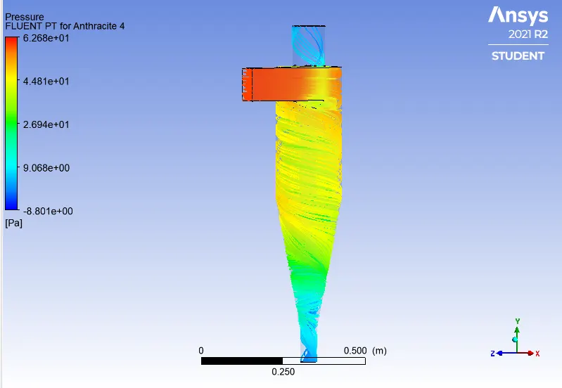
Case: 2 C
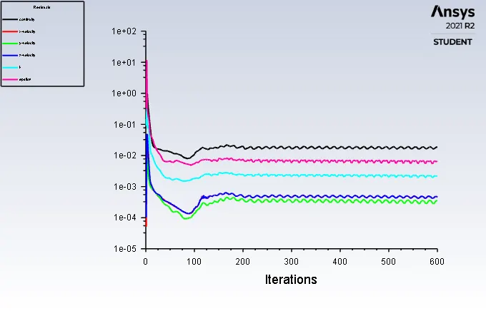
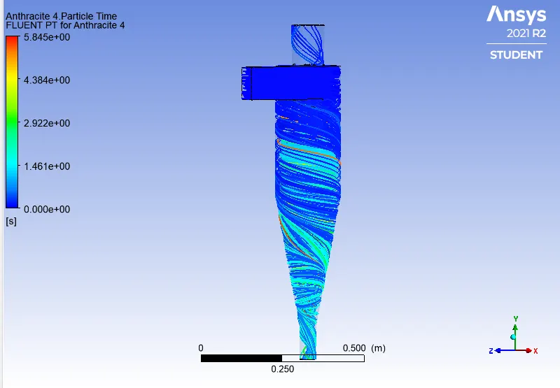
Separation Efficiency = (No. of Particles Trapped)/ (No. of Particles Tracked)
Separation Efficiency = (319/378)*100
Separation Efficiency = 84.391%
Pressure drop = Pressure at Inlet - Pressure at Oulet
Pressure Drop = 1.8489 - 0.6323
Pressure Drop =1.2166 pa
TABULATED RESULTS
|
COMPARISION OF RESULTS FOR THE CYCLONE SEPERATOR FOR VARING DIAMETER AS A CASE AND OTHER BY VARING THE VELOCITY |
|||||||
|
CONSTANT VELOCITY CASE V= 3 m/s |
|||||||
|
CASES |
X VELOCITY (m/s) |
DIAMTER OF PARTICLE(`mum`) |
PARTICLE TRACKED |
PARTICLE EXCAPED |
PARTICLE TRAPED |
SEPARATION EFFICIENCY(%) |
PRESSURE DROP (Pa) |
|
CASE 1 A |
3 m/s |
2 `mum` |
378 |
166 |
211 |
55.82% |
1.7016 Pa |
|
CASE 1 B |
3 m/s |
3 `mum` |
378 |
150 |
228 |
60.317% |
1.7016 Pa |
|
CASE 1 C |
3 m/s |
5 `mum` |
378 |
59 |
319 |
84.391% |
1.7016 Pa |
|
CONSTANT VELOCITY CASE D= 5 `mum` |
|||||||
|
CASES |
X VELOCITY (m/s) |
DIAMTER OF PARTICLE(`mum`) |
PARTICLE TRACKED |
PARTICLE EXCAPED |
PARTICLE TRAPED |
SEPARATION EFFICIENCY(%) |
PRESSURE DROP (Pa) |
|
CASE 2 A |
1 m/s |
5 `mum` |
378 |
57 |
320 |
84.656% |
1.848 Pa |
|
CASE 2 B |
3 m/s |
5 `mum` |
378 |
59 |
319 |
84.391% |
1.7016 Pa |
|
CASE 2 C |
5 m/s |
5 `mum` |
378 |
59 |
319 |
84.391% |
1.216 Pa |
CONCLUSION:
- There are several factors that can affect the cyclone separator efficiency, from the project we saw the two factors that are the diameter of the particles and the velocity of the particles on which the cyclone separator efficiency depends.
- Particle size and separation efficiency are directly proportional.
- Higher velocity is more effective for higher efficiency.
- The higher efficiency of the cyclone separator has a higher pressure drop.