Week 8 - Challenge 5 - Core & Cavity Design
Aim-1-To create the switch bezel plastic component through the given class-A-surface and at the end performing the draft analysis on the model.
2-Creat the core and cavity design of switch bezel component
Objectives-
- To ensure proper tree structure is followed.
- Geometrical sets should have a proper name based on the sketches present inside of it.
- All the sketches should be created under geometrical set.
- Use of the close surface feature to make a solid body from the surface.
- To publish the tooling axis ,Class A,B and C surface.
Procedure-
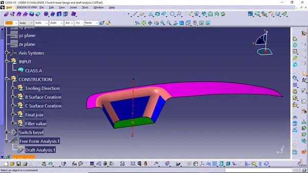
First import the class A surface of switch bezel model in CATIA V5.
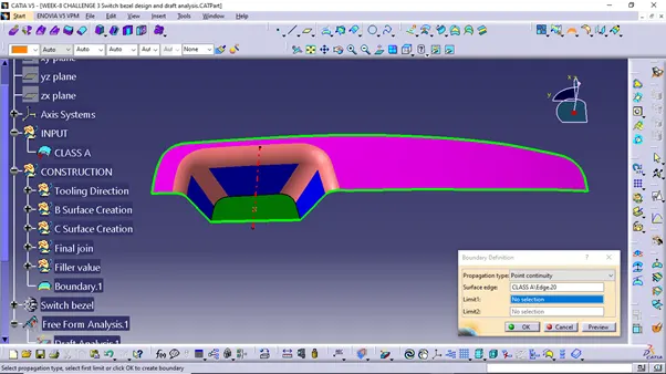
Check the connectivity of class A surface using boundry option.Ensure that there is no gap between the two surfaces.
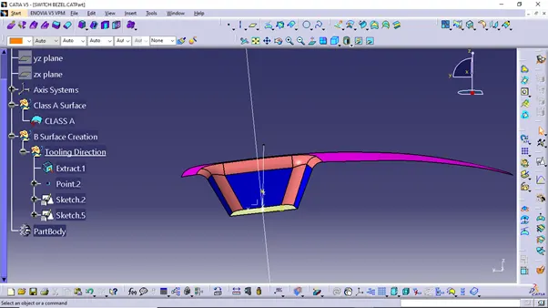
Tooling Axis- Now we need to create the tooling axis for the base bracket model. Visually check which direction is better for creating tooling axis. Now in order to create the tooling axis in Z-direction, first create a reference point on any surface as shown in figure.
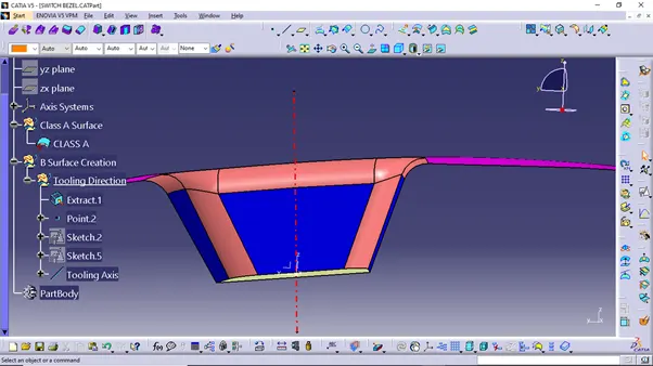
Now using the reference point create a line in Z-direction. This line will give us the tooling axis.
Creation of Class B Surface-
Consider the thickness of the component as 2.5 mm. Now we need to create a B surface which will be similar to the A surface at an offset value of 2.5 mm.
In this operation we are creating a class B surface in 3 different geometrical sets.
First we are creating a class B surface we need to extract the class A surface as shown in below figure.
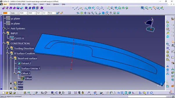
Once the surface is extracted untrim it and then extrapolate it by a required value on each side using continuity. Now offset it by 2.5 mm.
Similarly we need to extract the walls and base surface of the switch bezel in different geometrical sets and perform similar operation on it as mention above.
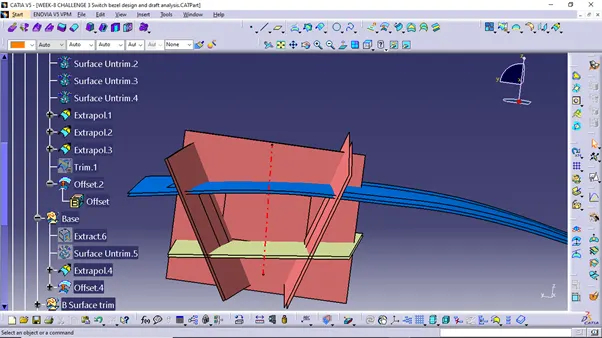
Once all the surfaces are created trim these surfaces to form a class B surface.
Give the appropriate fillets to form Class B surface.
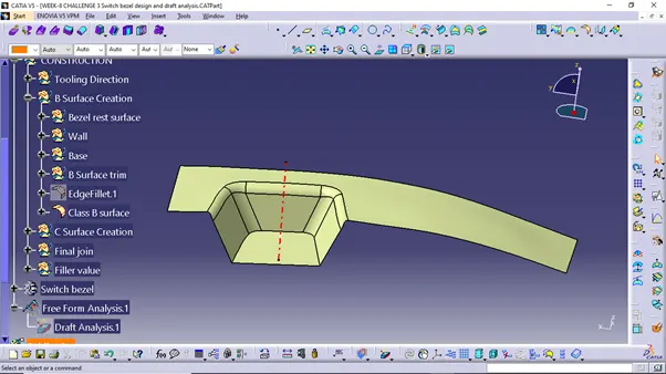
Creation of Class C surface-
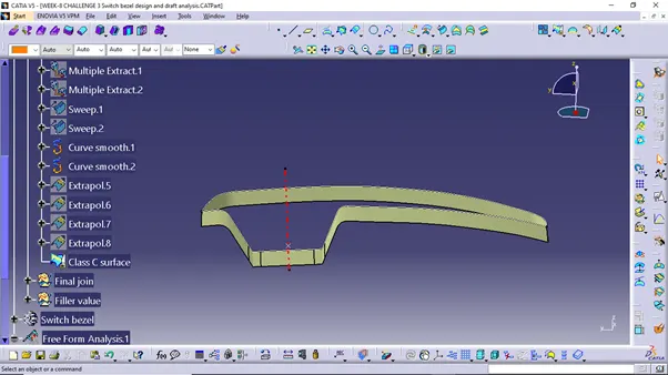
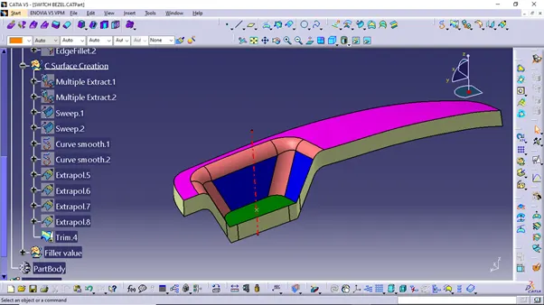
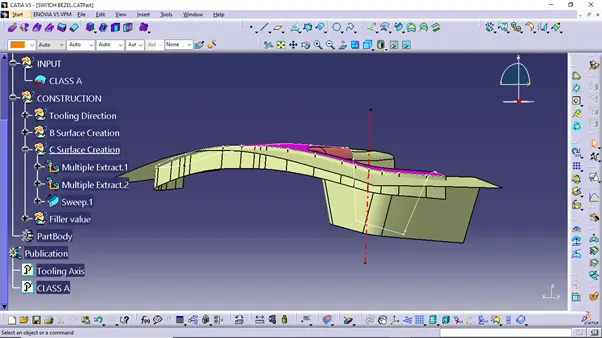
To create a class C surface ,first extract the boundaries of the Class A surface and give them smooth curve as shown in figure below.
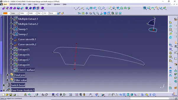
Now using the sweep option to create the class C surface.
Trim surfaces-
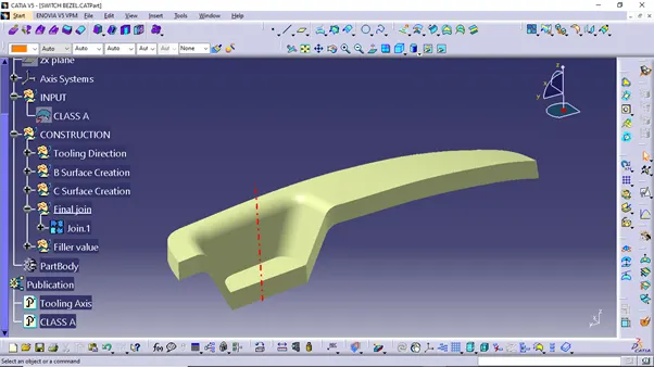
After creation of Class A, Class B and Class C surfaces, we need to join Class A and Class C surface to form a new surface. Then trim the joined surface with Class B surface to form the final required surface.
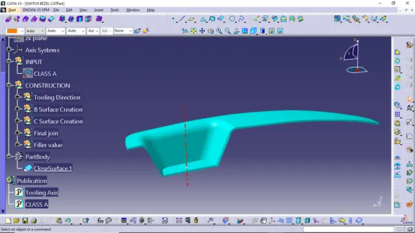
Isometric view
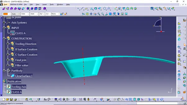
Front view
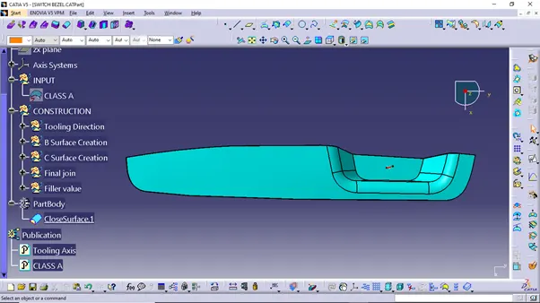
Top view
Now using the close surface option from part workbench form a solid body.
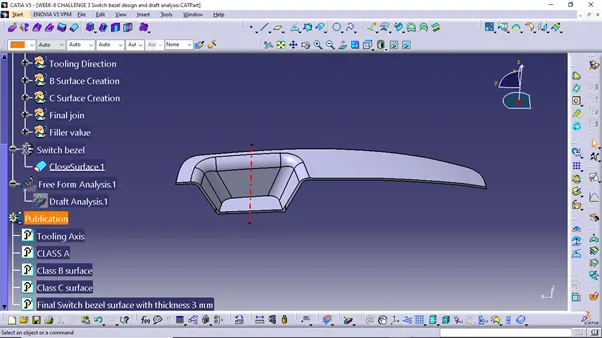
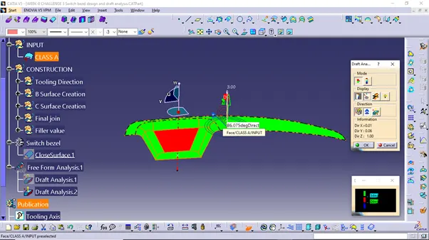
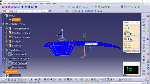
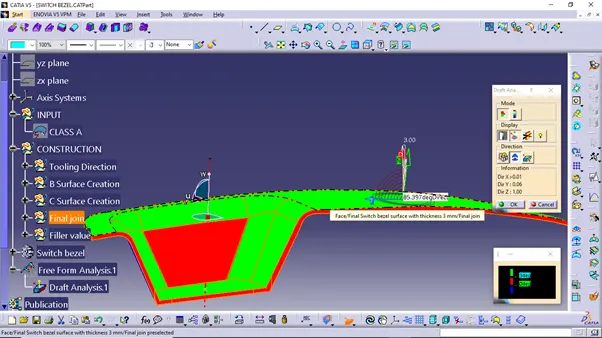
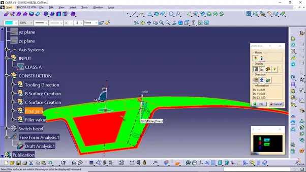
Draft Analysis- To perform draft analysis on the switch bezel model ,first set the view parameters to Material mode.
To give the draft direction use the compass and align Z-axis of it with the final tooling axis for the switch bezel model. Once it is properly aligned, lock the daft direction. Select the switch bezel and it will show us the current draft angle of the model.
Class A Surface Draft Analysis
Solid body draft analysis
CORE AND CAVITY BLOCK DESIGN OF SWITCH BEZEL
- The mould core and cavity are the shaped section in either half of the mould tool which give the plastic product its final shape.
- The hot molten material is injected in to the core and cavity and then sets hard in to shape. The design of the core and cavity is essential in the correct formation of the product. The sequence of events during the injection mould of a plastic part is called the injection molding cycle.
- The cycle begins when the mould closes, followed by the injection of the polymer in to the mould cavity.
- A core is usually made of the best quality sand and is placed in to the desired position in the mould cavity. Core prints are added to both sides of the pattern to create impressions that allow the core to be supported and held at both ends.
CORE
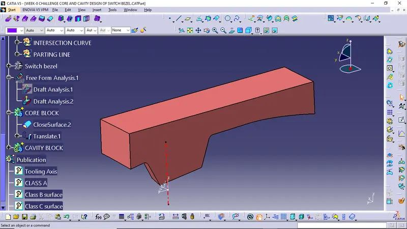
- The core design is started with extracting the parting surface that becomes the datum for the core and cavity. The parting surface in most of the cases is kept at the B class surface to avoid close and tight contact between the core and cavity.
- At first the A-class surface is extrapolated with some length and later it is trimmed with a C surface.
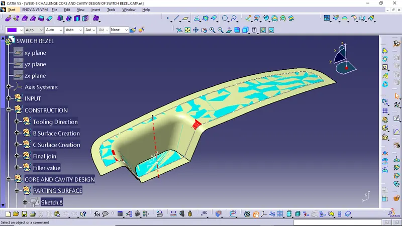
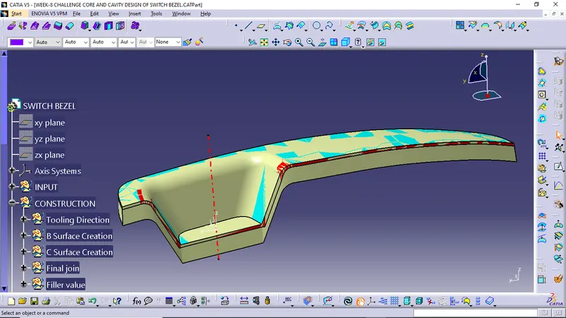
This A and C surface again trimmed with the B surface to form the core face.
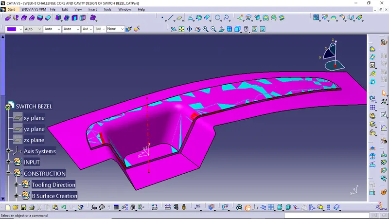
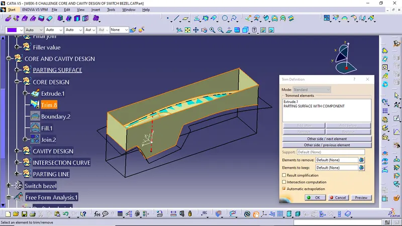
- Now the final core block is made by drawing the boundary sketch and extruding it along the tooling axis direction followed by the filling and thickening.
CAVITY
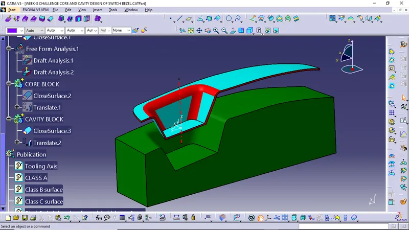
- The cavity is the part where the injector and filling of the molten plastic happens. The cavity block is prepared by first extruding the outer boundary along the tooling direction.
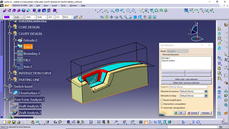
- This outer surface is trimmed with the B class surface and then it is filled and thickened.
PARTING LINE AND PARTING SURFACE
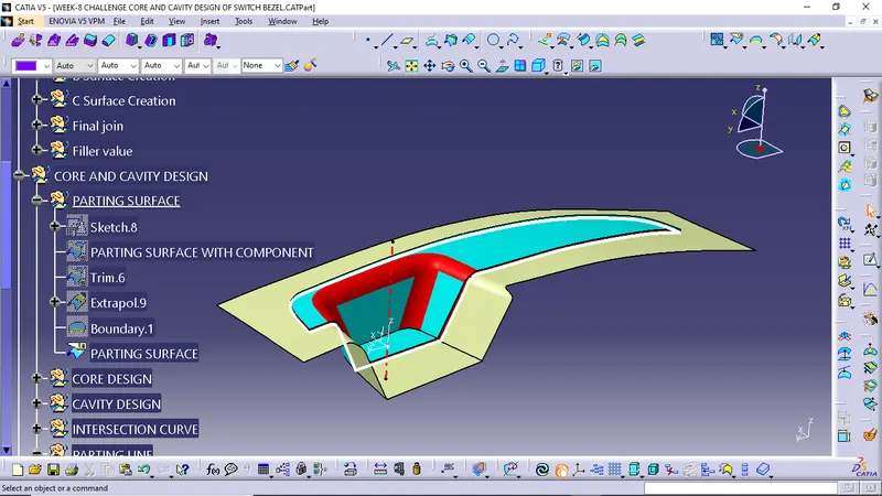
A parting line in the industrial casting of molds, is the borderline in which draft angles change direction. That is it is the dividing line that splits the core and cavity halves of a molded part. It is sometimes a starting point for the mold parting surface.
The parting surface of a mould are those surfaces of both mould plates adjacent to the impressions which both together to form a seal and prevent the loss of plastic material from the impression.
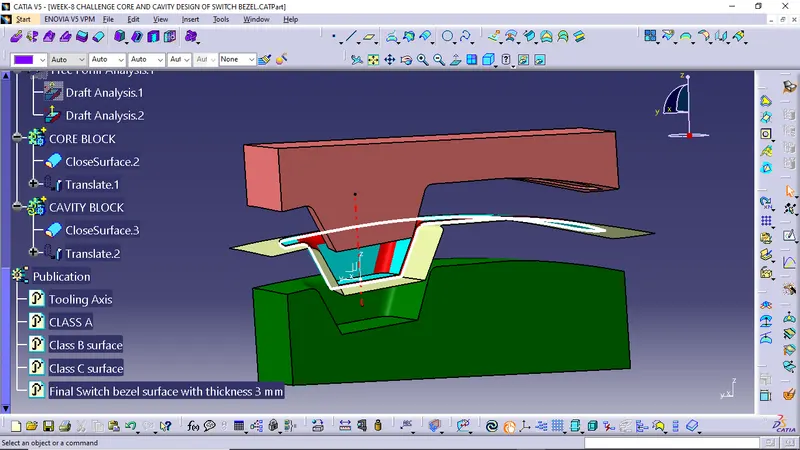
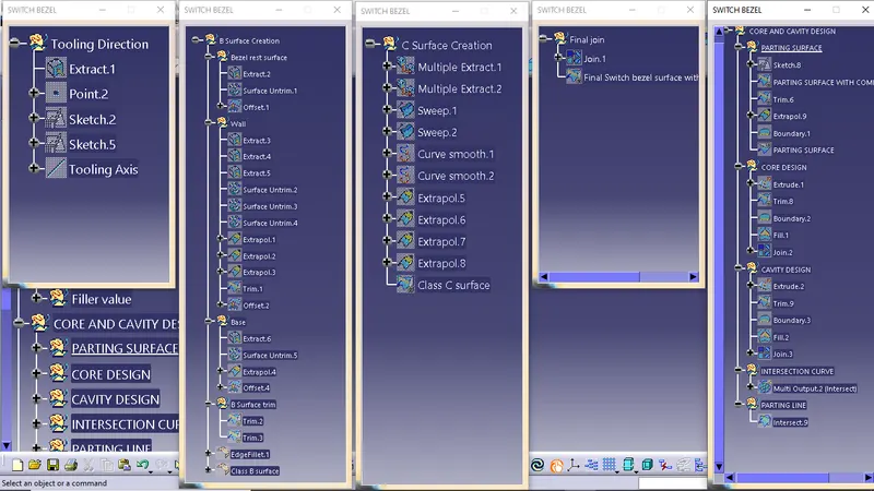
TREE STRUCTURES
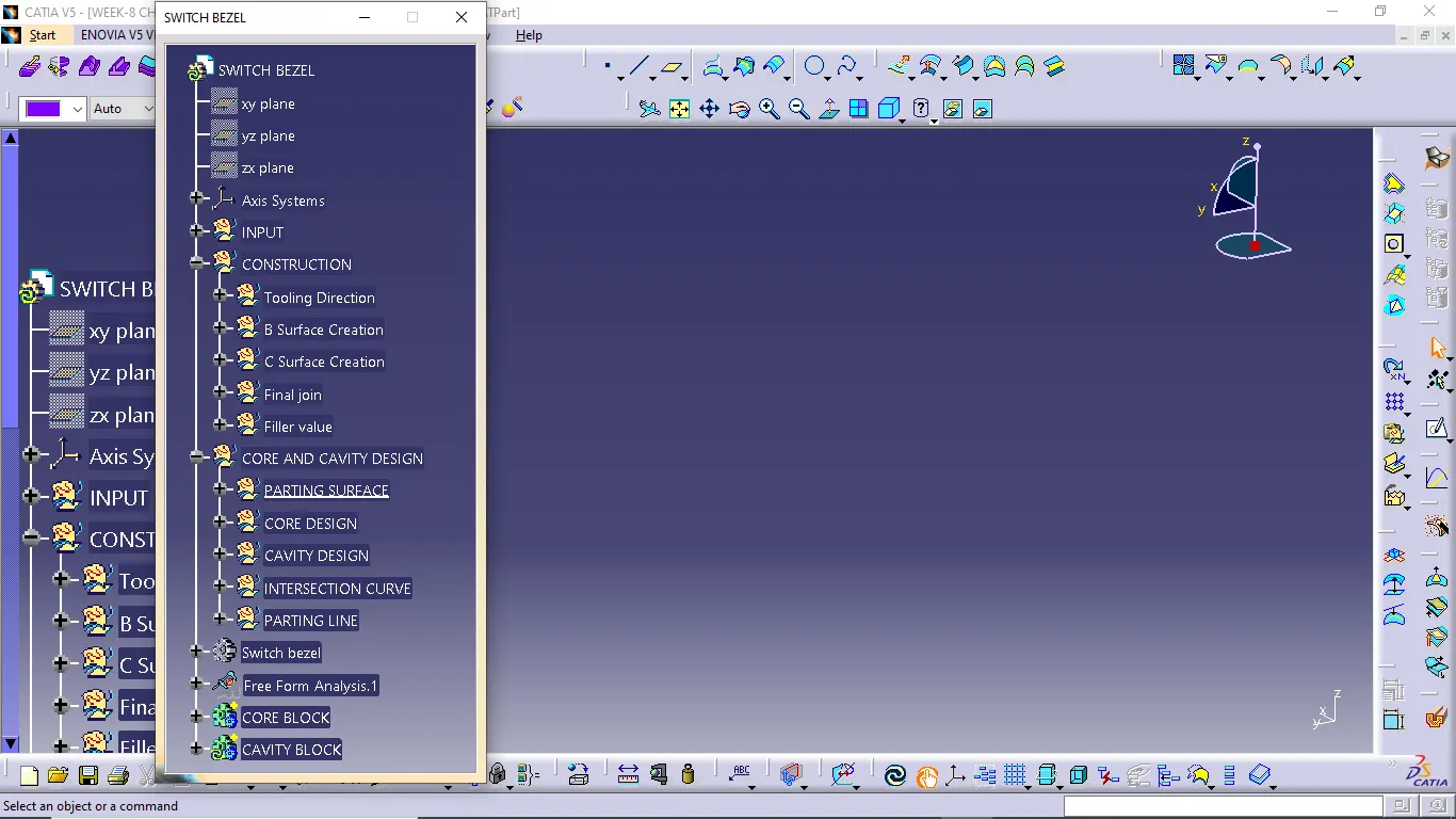
SWITCH BEZEL MODEL
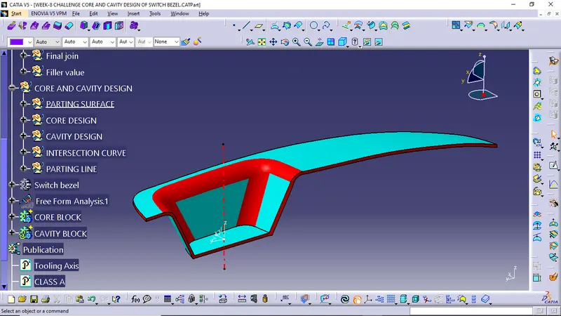
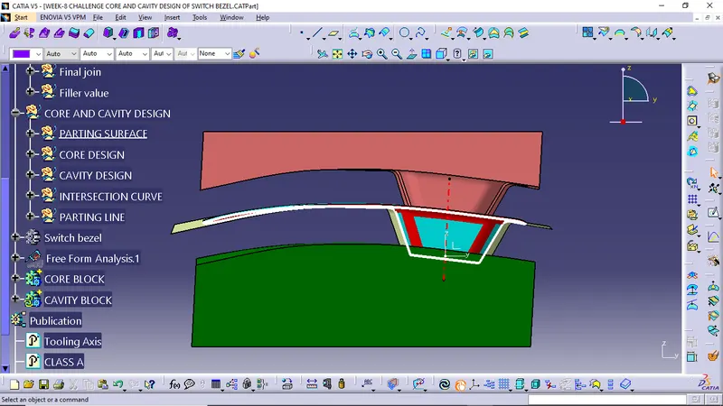
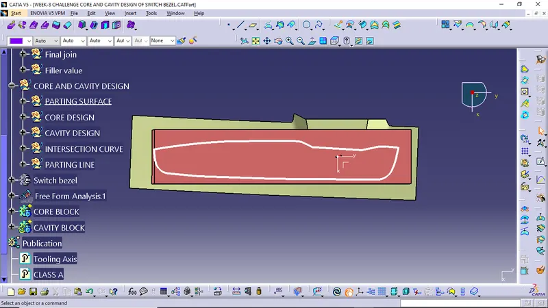
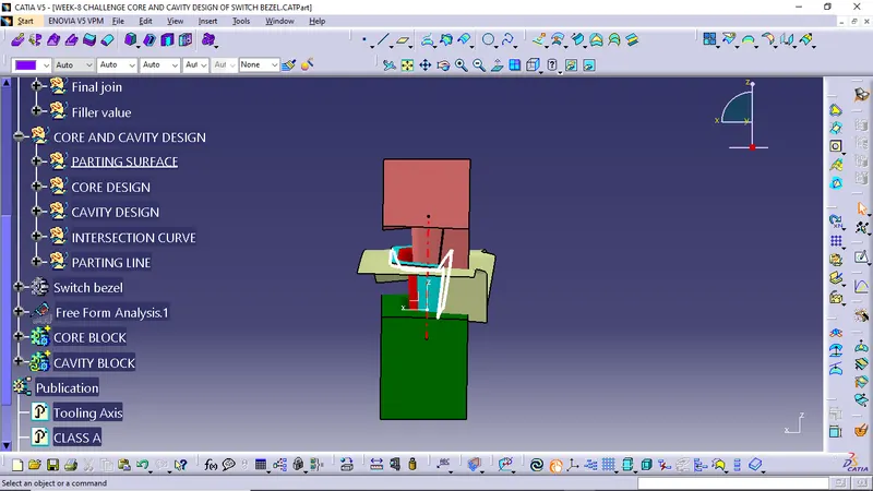
CORE AND CAVITY MODEL
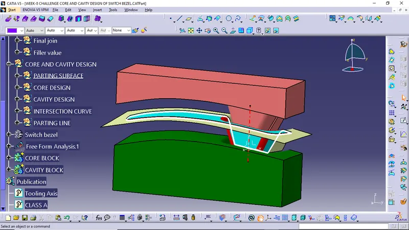
FRONT VIEW
TOP VIEW
SIDE VIEW
ISOMETRIC VIEW