Challenge 4 : Concept Modelling of Alloy Wheel
Concept modelling of Alloy wheel
Objective: - My objective is to make the surface modelling of car alloy wheel
- Image which is provided by skill-Lync
- Image which is taken by itself is to be done using Autodesk Alias.
Introduction: - Autodesk-Alias which as an automotive design software deals with surfaces. Since an automotive software its fare to say that it might be (CAD and CAID) almost seems identical but there are some noticeable differences. CAID follows a thought process which requires conceptual imagination and visualization. Where as CAD deals with technical terms. This powerful software with having many and many tools which can be used to achieved the final desired shape of the model. My task is also same to visualize and create the surface model of car alloy wheel and try to get as close as it.
Approach: -

- Setup of canvas image of alloy wheel
First of all, select the layout (Left) which is required and then import the images of alloy wheel as canvas images.
Image provided by skill-Lync

Image setup
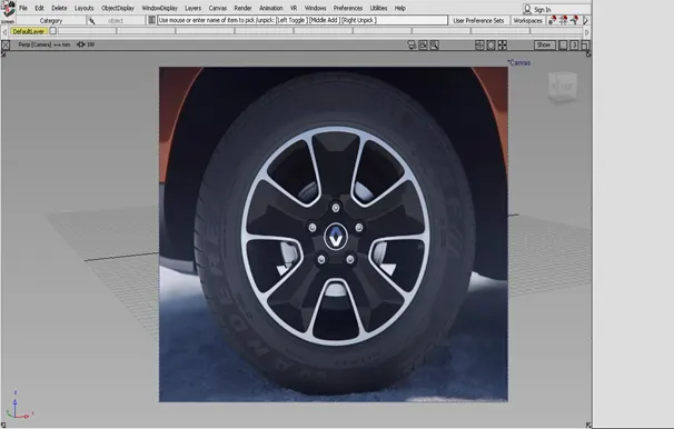
2. Creating curves on images
Tools used for creating curves
1.CV curves - Creates new NURBS curves in the scene by placing CVs
The mathematical degree of the curve created, which control the number of CVs per span: 1 (linear), 2 (quadratic), 3 (cubic), 5 or 7. The default is 3.
Specifies the initial position of the curve's pivot points (both rotation and scaling).
Origin – The pivot points are located at (0, 0, 0).
First CV – The pivot points are located at the position of the first CV, that is, the start of the curve. This is the default.
Last CV – The pivot points are located at the position of the last CV, that is, the end of the curve. The pivots position is re-calculated and displayed every time a new control point is placed.
2. Key point curves- Allows you to create a single key point line
Specifies the degree of the curve. The values range from 1 to 7. The default is 1.
3.Blend curves - Use the Blend Curve Create tool to create the initial shape of the curve. Then you can add, edit, or delete the initial constraints using the constraint tools.
The mathematical degree of the curve created, which control the number of CVs per span: 1 (linear), 2 (quadratic), 3 (cubic), 5 or 7. The default is 5.
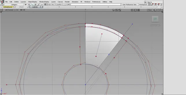
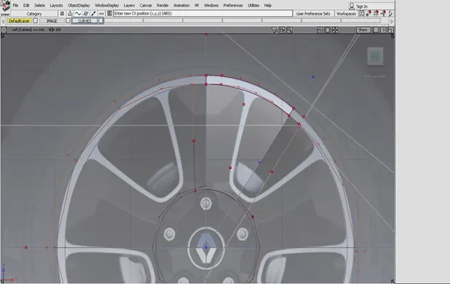
3. Creating surfaces on curves
Tools used for creating the surfaces.
1.Skin tool
2.Square tool
3.Rail tool
4.Trim and Un trim tool
5.Project tool
6.Surface fillet
7.Freeform blend tool
8.Planer tool
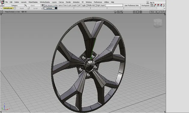
Above mentioned tools are used to create the below shown image of fully formed surface of alloy wheel
Its not necessary to use all the features to create the surfaces every time. It does not matter what features you have used to achieve the final shape.
Partial surface creation
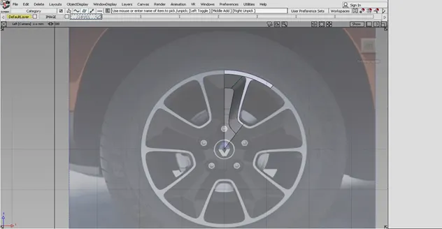
Create the symmetry surface
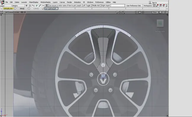
Creating the holes
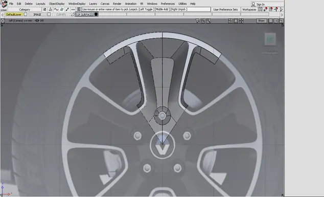
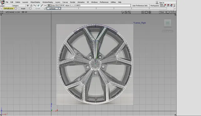
Creating full alloy wheel surface
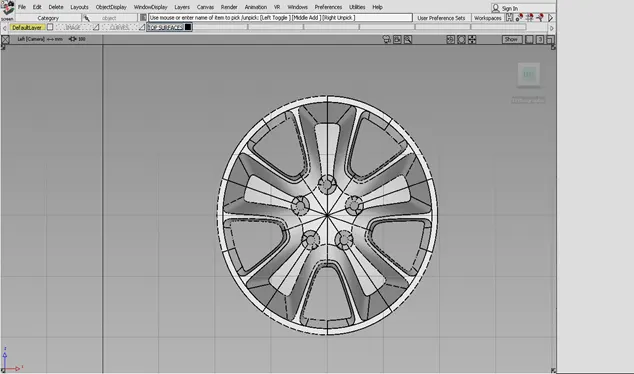
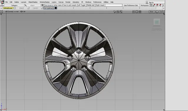
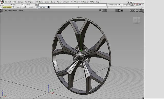
Perspective images
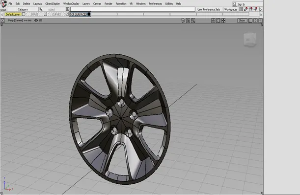
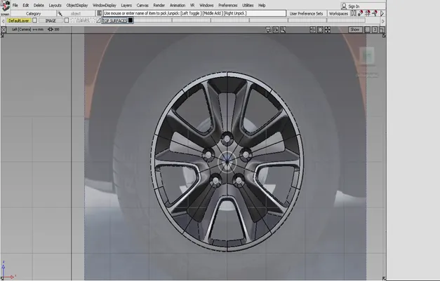
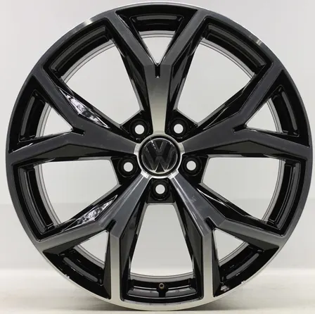
We will now use personal selected images of alloy wheel.
Images of alloy wheel
Creating curves
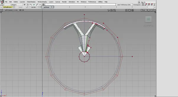
Partial surface creation
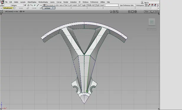
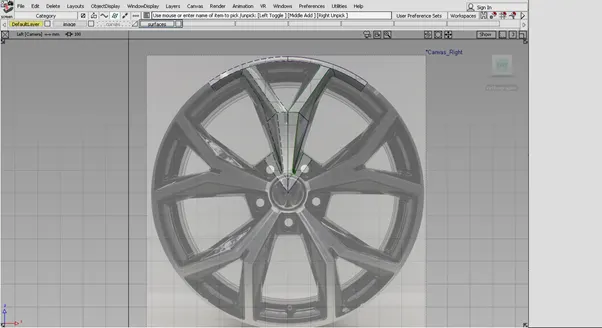
Full surface creation
Perspective view
Conclusion-
After performing this work and making my on-alloy wheel. I came to know that how to actually form the desired shape of any alloy wheel. I have learnt how to perform certain task faster and easier.