Surface modelling of Bugatti Veyron car
Objective: - My objective is to make the surface model of Bugatti Veyron car through Autodesk-Alias provided by skill-Lync.
Introduction: - Autodesk-Alias is basically automotive design software which deals with surfaces. Autodesk-Alias is a family of Computer aided industrial design (CAID) software predominantly used in Automotive design and industrial design for generatingclassA surfaces using Bezier and nurbs modelling method. Its entire work is dependent on visualization and the thought process of the software user, it’s a very powerful software with having many and many tools which can be used to achieve the final desired shape of the model.
Design Methodology: -
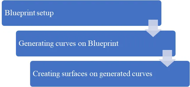
1. Blueprint setup
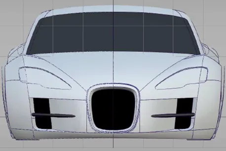
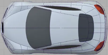
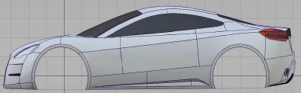
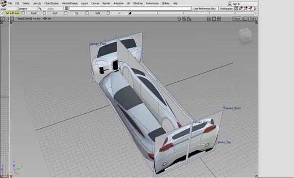
First of all, we convert the blueprint images of car in to four views like
(Front view, Back view, Right view and Top view).
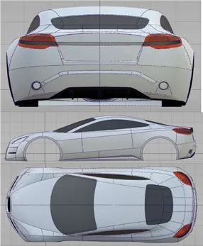
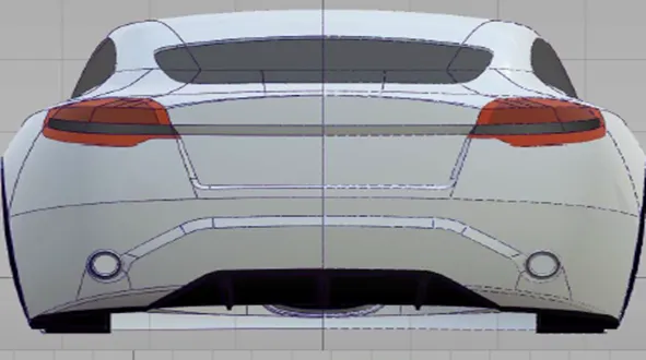
Back views
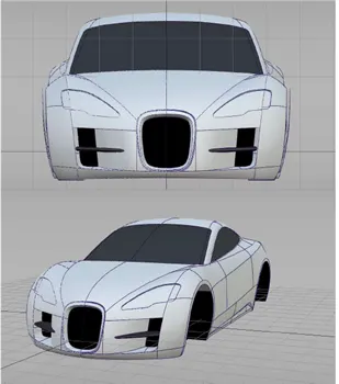
Front views
Top views
Right views
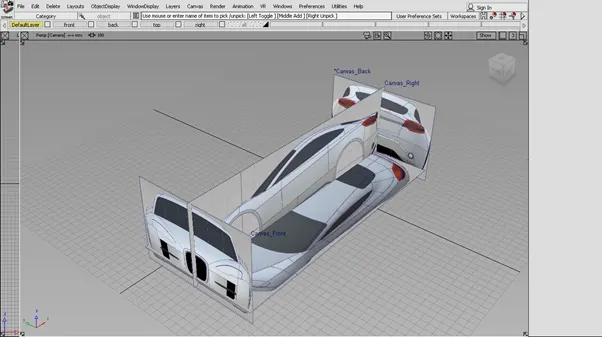
Now we select the layouts of all views one by one and importing the canvas images of all views one by one.
After importing of images we scale it and adjust the all images in required position.
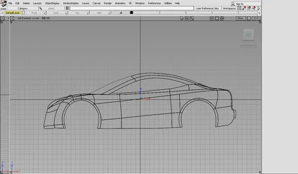
2.Generating curves on canvas images
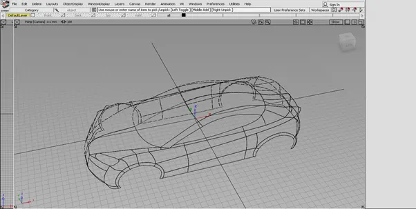
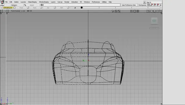
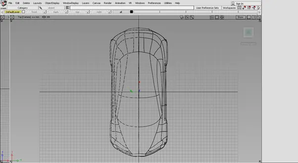
Following features are used for creating the curves.
- CV curves
- Key point curves
- Blend curves
Perspective view
Front view
Top view
Right view
3. Creating surfaces on this curve sketches model
Features used for creating surfaces.
1.Skin tool – Creates a surface across a set of curves.
Skin control
Proportional Crown
Select this option to raise or lower the midpoint of the surface between two input curve sets so that the height or crown of the surface is proportional to the distance between the curves. The setting makes the surface degree 2 with a single row of CVs in the center. This option is not available when more than two curve sets are selected.
You can control the Proportional Crown directly on the surface.
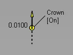
To turn the crown off, click On.
To change the crown value, drag the circle of the crown manipulator. The value adjusts in 0.005 increments. Use the left mouse button for adjustments, the middle mouse button for fine adjustments.
To flip the crown, click the dashed line.
Crown Flip
Flips the direction of the crown.
Click the arrow of the proportional crown manipulator to Flip the crown direction directly on the model.
Crown Value
Controls the height of the crown. The value corresponds to a percentage of the distance between the two rails. The slider ranges from 0.0 to 0.1, but larger values can be entered into the field.
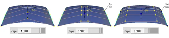
Crown Shape
Increase the degree of the surface from 2 to 3, giving two central rows of CVs. Shape values less than 1 move these CVs closer to the edges of the surface, positive values move them closer to the center.
2. Square tool – Creates surfaces by blending four boundary curves (or curve segments), while maintaining continuity with adjacent surface.
Square Control
Continuity table
The Continuity Table displays one row for each boundary curve involved in the Square operation.
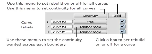
Use the pop-up menu next to each curve to set the level of continuity you want across that curve.
Use the Continuity pop-up menu above the table to set the continuity you want for all of the curves at once.
Click the checkboxes at the end of each row to rebuild the curves to reduce data and improve parameterization.
Use the Rebld pop-up menu to set rebuild on or off for all the curves at once.
Continuity
Free Boundary – This edge is free to move if required by another edge’s continuity or by the Influence sliders (see below). This is the default.
G0 Position – Keep this edge exactly like the boundary curve that created it. In other words, do not let the edge move as with the Free option. This is equivalent to positional continuity.
G1 Tangent – Try to keep tangency with a surface that shares this edge.
G2 Curvature – Try to keep curvature continuity with a surface that shares this edge.
Implied Tangent – Try to keep tangency with an implied surface that shares this edge. The implied surface is the surface that would be created by mirroring the new surface. (The way the Square tool tries to keep tangency with an implied surface is by blending the slopes of the boundary curves.)
This is a powerful feature. It lets you model one half of a symmetrical surface (such as a car body), and maintain continuity at the seam. When you duplicate the surface to create the other half, the seam will already be continuous. For this to work across a symmetry plane, you must make sure the ends of the curves are tangent across the symmetry plane (that is, the tangents are perpendicular to the symmetry plane).
Implied Curvature – Try to keep curvature continuity with an implied surface that shares this edge. The implied surface is the surface that would be created by mirroring the new surface.
Tangent Angle – Try to keep tangency at an angle with a surface that shares this edge.
When you set this continuity type for an edge, a manipulator appears on the edge. Use the manipulator to set the tangent angle.
The two adjacent edges of the new surface should be Free to allow the Tangent Angle edge to move.
Setting the Tangent Angle manipulator to 0 or 180 degrees is the same as using G1 Tangent continuity.
3. Birail surface generation tool
Creates a surface by sweeping one or more profile curves along one or two path curves (rails).
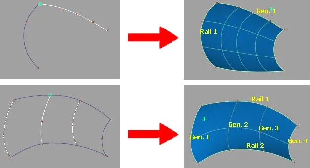
The Rail Surface tool takes its name from its use of one or two “rail” curves. The generation curves maintain contact with the rails at the same points through the sweep, like a train traveling on a track.
The Rail Surface tool is similar to the Extrude tool, but has many more options and much more power.
The appearance of the Rail Surface icon depends on the Generation Curves and Rail Curves settings in the Rail Surface Options window.
4. Multicolour diagnostic shader tool
Shades all the picked surfaces with a single colour. Useful for detecting bumps, dents, or other surface irregularities.
The Multi Colour icon shades all the picked surfaces with a single colour that you can choose. Use this shading mode to see how your model looks as a finished product, and detect any bumps, dents or other surface irregularities.
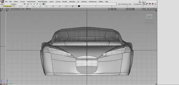
Front view
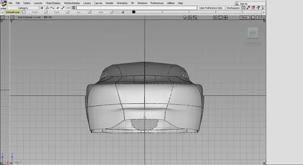
Back view
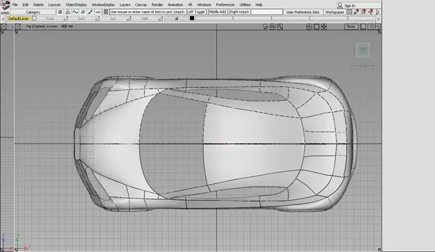
Top view
Right view
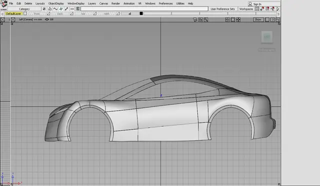
Perspective view
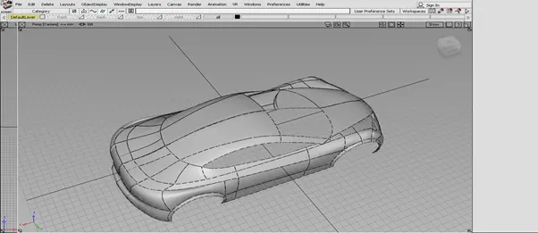
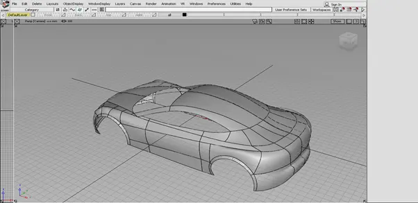
Conclusion
After performing this work and making this model we came to learn that how to setup the blue print of any car model, how to create the sketches on blue print and how to create the surfaces on sketched curves.