Week 8 - Challenge 4 - Coin Holder Design
AIM:
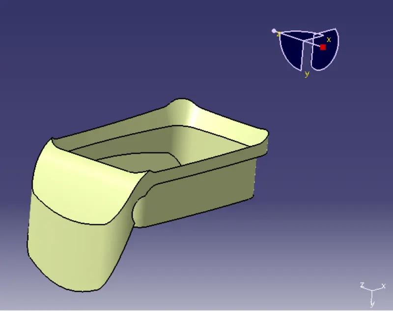
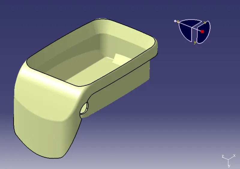
To create the Coin Holder Plastic component through the given Class-A surface and add the thickness and perform the draft analysis on a solid surface.
OBJECTIVE:
The objective of the challenge is to create a Coin Holder Design along the solid part body from class A surface in CATIA surface workbench and part design.
- To create a class B & C surface for the given component.
- To form a tooling axis.
- To perform a draft analysis.
1. INPUT CLASS A SURFACE:
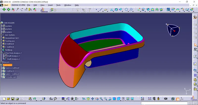
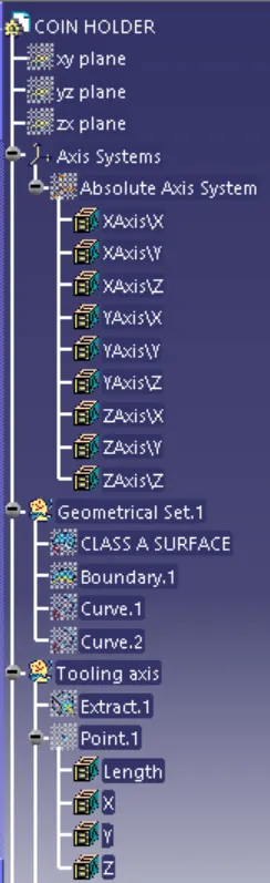
Check for any boundary opening therein given Class-A surface using the Boundary command.
2. TOOLING AXIS CREATION:
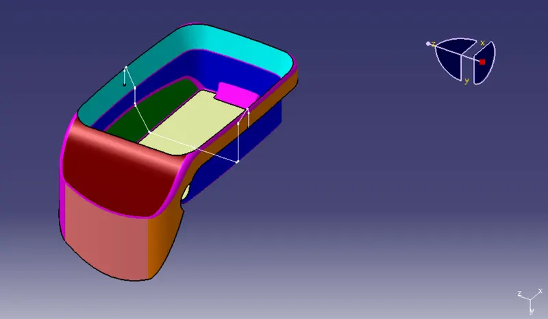
The Tooling Direction is basically the direction that the mold pulls apart. The mold is built in two separate pieces, basically. You have a Cavity side and you have the Core side. The Core pulls apart from the Cavity and that's the Dyeline or the Tooling Direction.
- analyzing the model visually to see the most efficient side suitable for the tooling axis from the image below image.
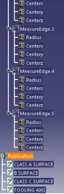
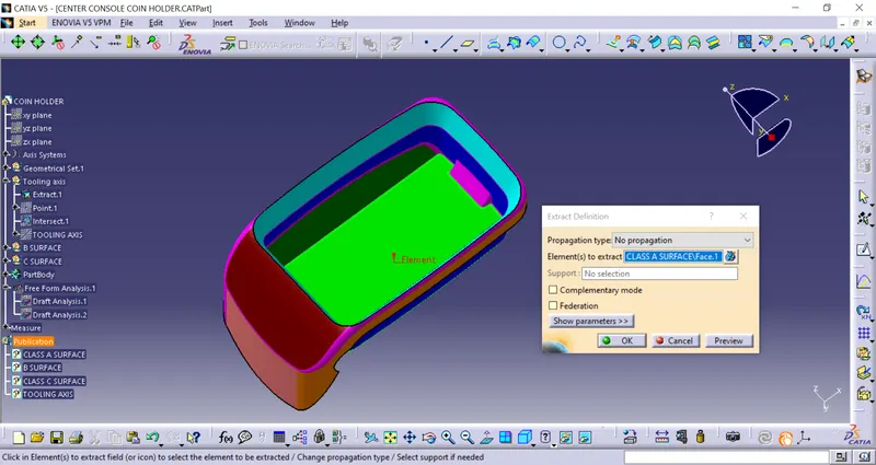
- Extrude the surface to create a point and temporary axis.
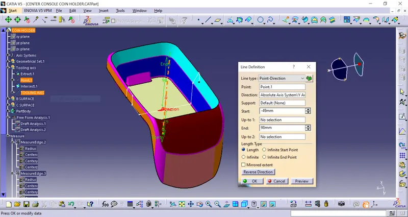
3. DRAFT ANALYSIS ON THE CLASS-A SURFACE:
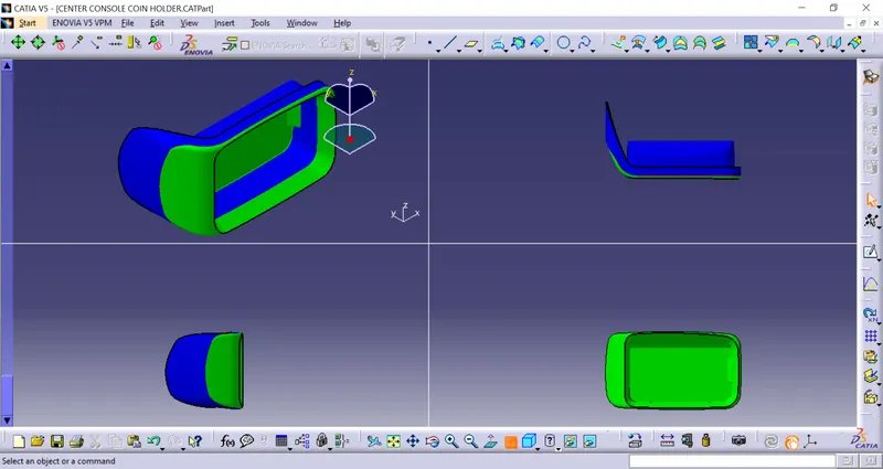
- First, change the parameter to material mode and then go to perform draft analysis Go to Insert > analysis > feature draft analysis.
- Click on the compass icon & align with the tooling axis.
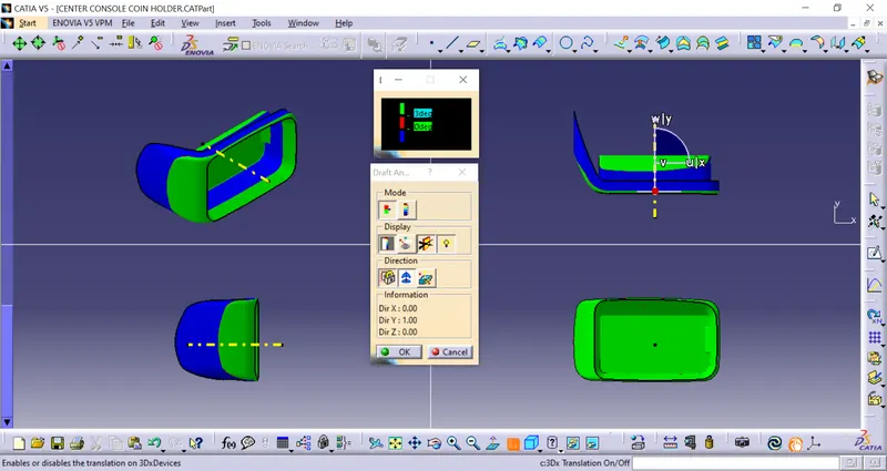
- from the above image, we see the surface in green color has more than a 3degree draft which is required for tooling feasibility.
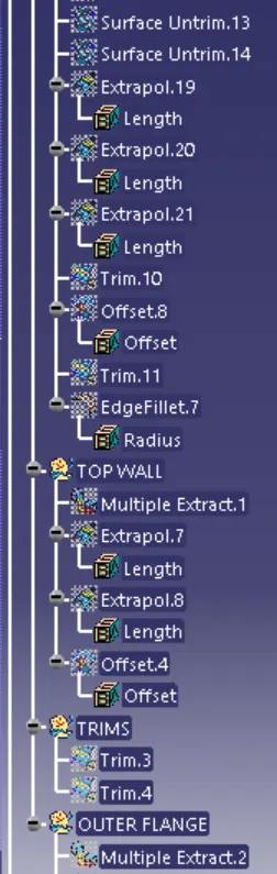
4. CLASS-B SURFACE:
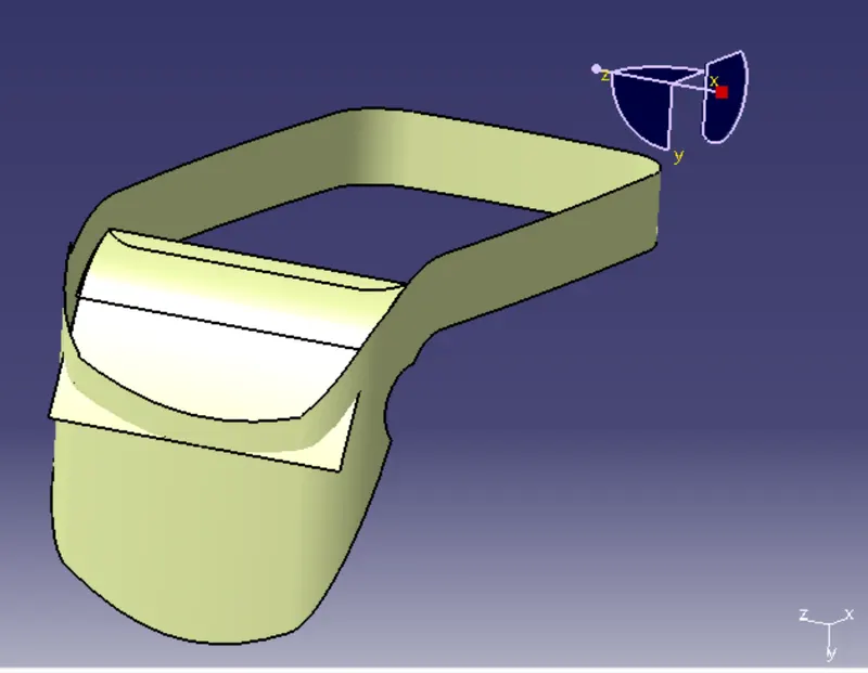
We subdivided the class-A surface by
- Sidewalls
- Base
- Top walls
- Outer Flange
1. Sidewalls:
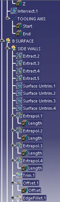
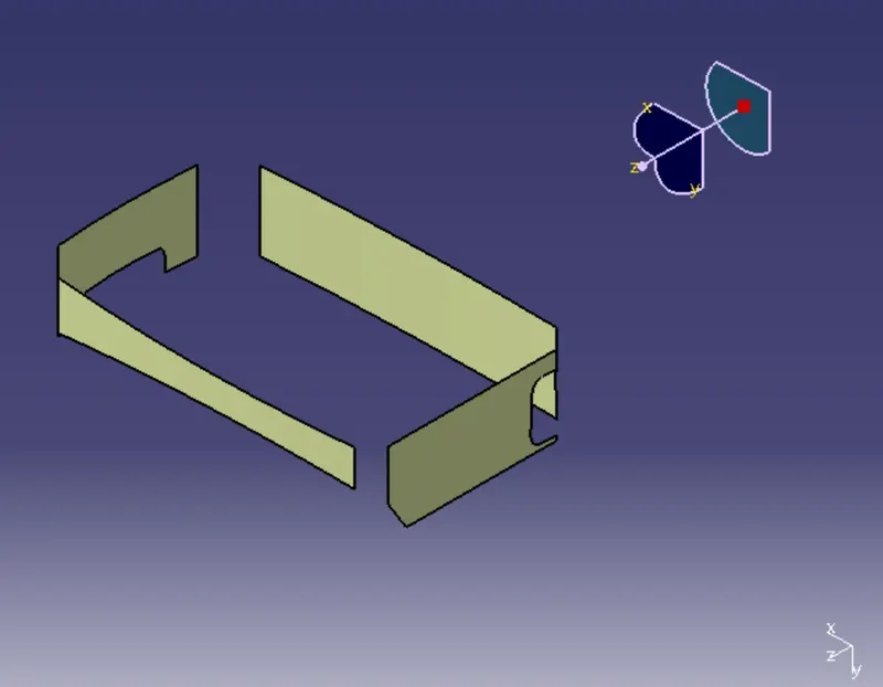
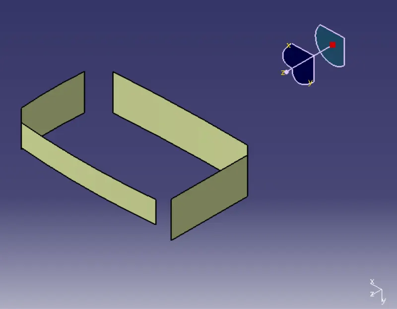
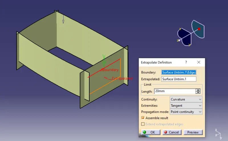
- we take the extract of the side walls from the class A surface.
- Surface Untrim the extracted walls.
- Extrapolate the walls by some distance.
- Trim the side walls to combine single walls.
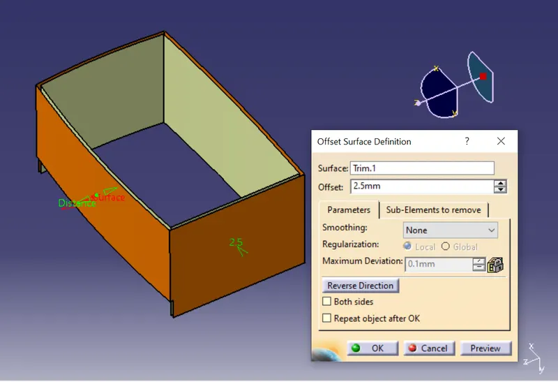
- Offset the wall by 2.5mm by outside as shown below image.
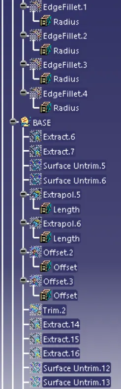
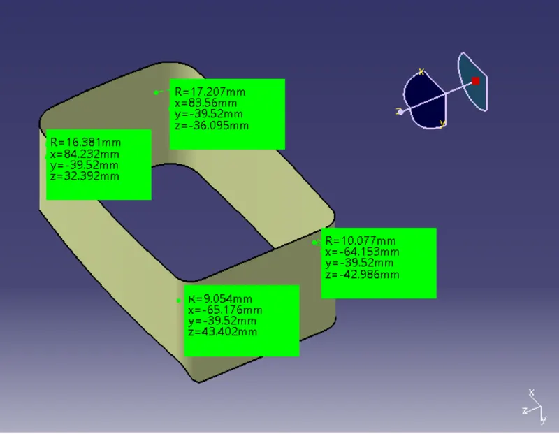
- Given the radius value of the sharp edges of corners by Class-A surface radius + 2.5 mm.
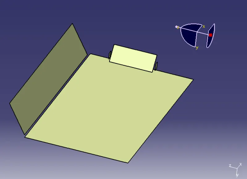
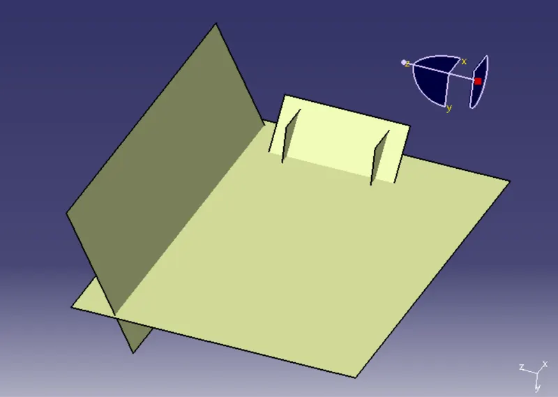
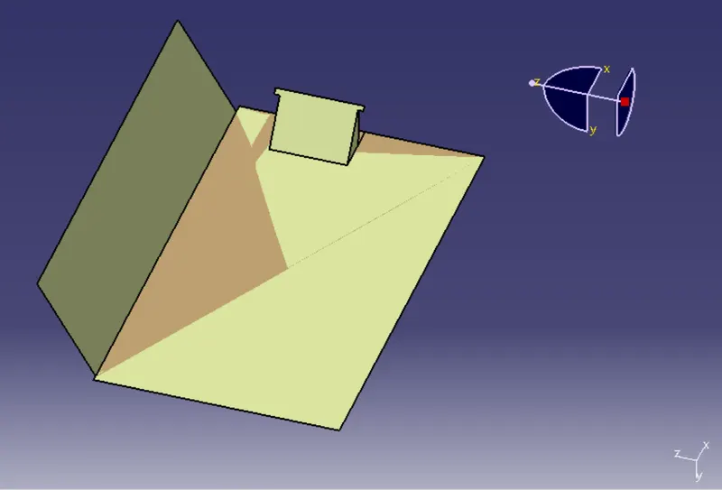
2. Base:
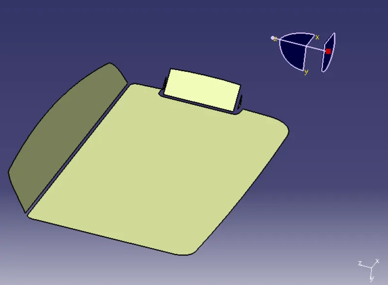
- we take the extract of the Base from the class A surface.
- Surface Untrim the extracted walls.
- Extrapolate the walls by some distance.
- Trim the side walls to combine single walls.
3. Top walls:
- Extract the top wall surrounding the class-A surface.
- extrapolate the surface by both sides offset the top walls by 2.5mm
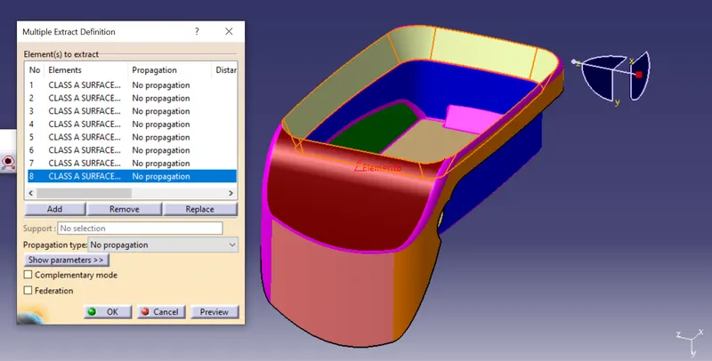
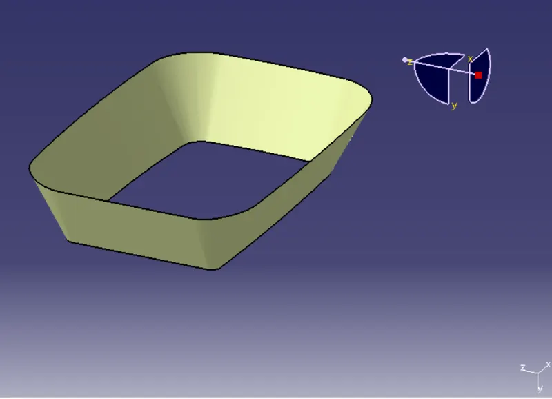
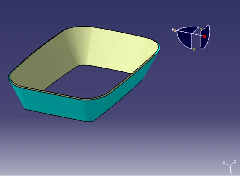
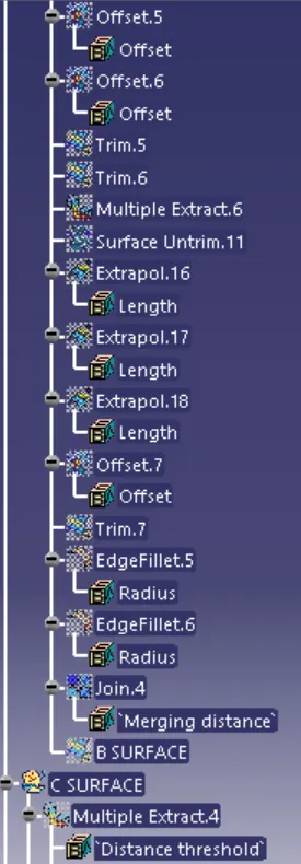
Trim the sidewalls, base, and top walls
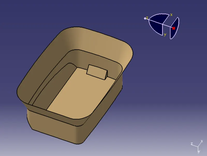
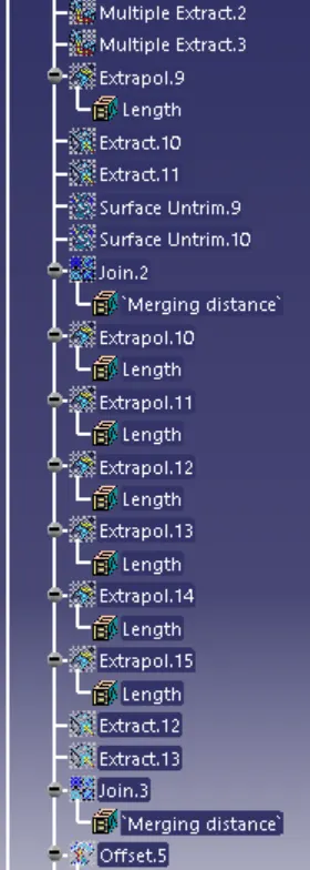
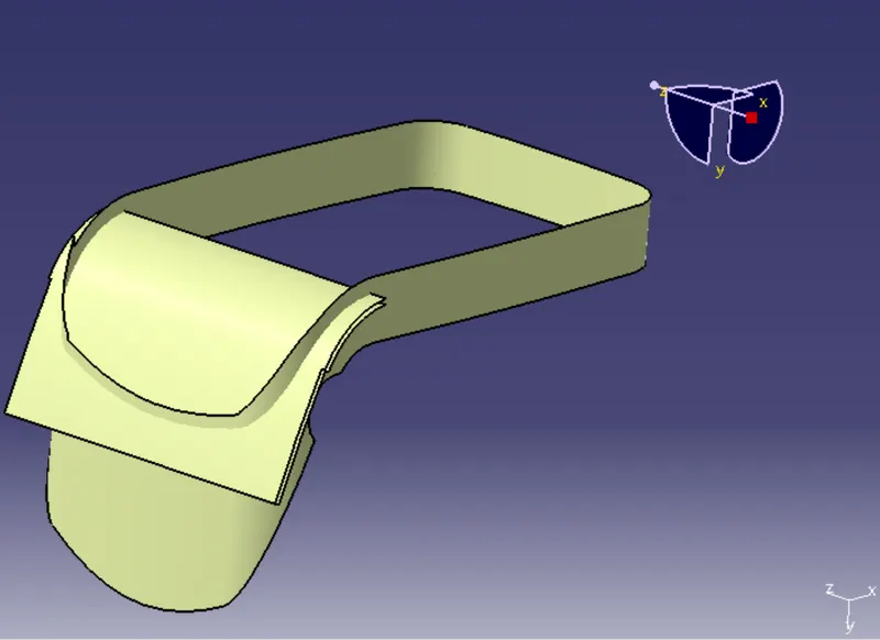
4. Outer Flange:
- we take the extract of the outer walls from the class A surface.
- Surface Untrim the extracted walls.
- Extrapolate the walls by some distance.
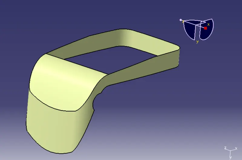
- Trim the side walls to combine single walls.
- Finally Class-B surface formed.
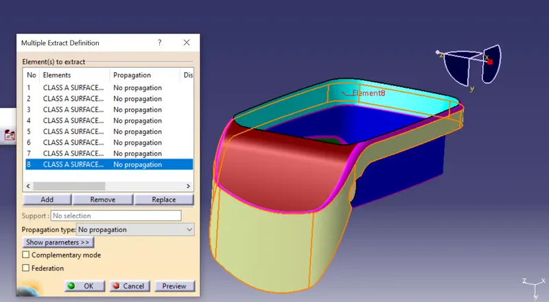
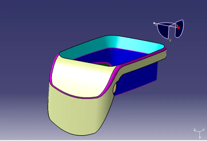
5. CLASS-C SURFACE:
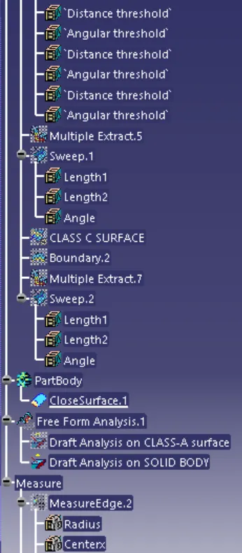
The surface will be created using the sweep command by sweeping the boundary of Class-A surface along the tooling axis along the A-B surface is known as CLASS-C surface.
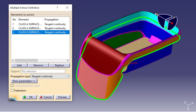
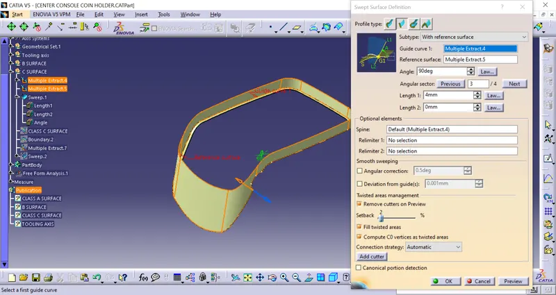
after creating a Class-C surface using the B and C surface created a closed surface will be formed by using trim commend.
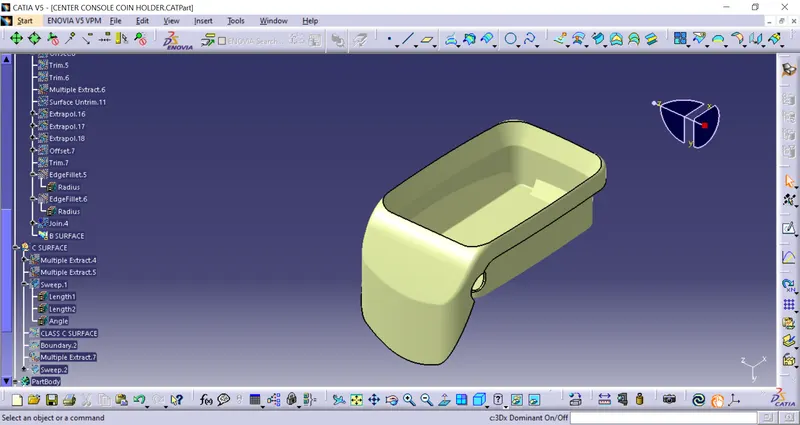
- After creating the closed surface go to the part workbench to form a solid part from the closed surface using close surface commend.
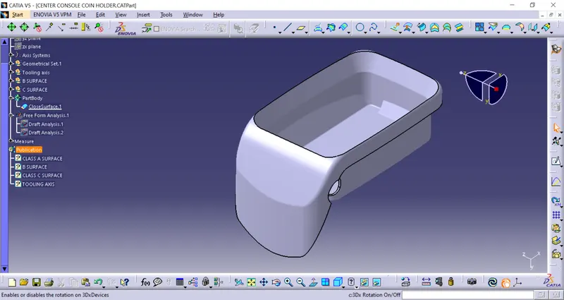
6. DRAFT ANALYSIS ON SOLID PART BODY:
- After creating the solid body again I will perform the draft analysis but this time the whole part body.
- I follow the same process I do on the class-A surface.
- First, change the parameter to material mode and then go to perform draft analysis Go to Insert > analysis > feature draft analysis.
- Click on the compass icon & align with the tooling axis.
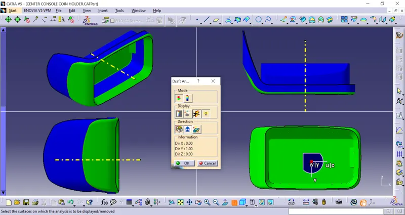
- from the above image, we see the surface in green color has more than a 3-degree draft which is required for tooling feasibility.
- The below image is analyzed under the running point to see the angle of the surface.
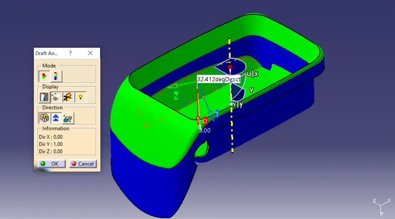
various orientations (Isometric, Front, Side, and Top View)