Week 8 - Challenge 1 - Draft Analysis on a Fan Cover
OBJECTIVE
Creating the tooling axis for the given Fan cover model meeting the requirements of the draft angle and performing the Draft analysis on the model.
DETAILED REPORT:
1) CHECKING CONTINUITY OF A GIVEN CLASS-A SURFACE:
We have to check the continuity of a given class A surface to ensure it is properly joined or no gap is present. the commend we use JOIN or Boundary in the operation toolbar.
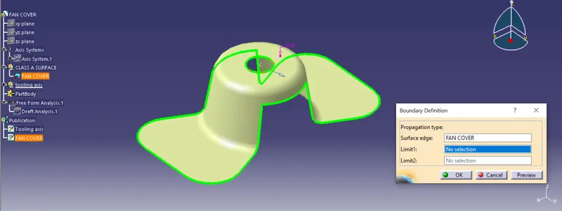
- By looking above image as highlighted by the green line the surface has a continuously connected boundry.
- After we process the Boundary command we check the continuity of a class A surface visually from the below image.
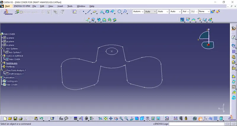
2.Tooling axis direction:
The Tooling Direction is basically the direction that the mold pulls apart. The mold is built in two separate pieces, basically. You have a Cavity side and you have the Core side. The Core pulls apart from the Cavity and that's the Dyeline or the Tooling Direction.
- analyzing the model visually to see the most efficient side suitable for the tooling axis from the image below image.
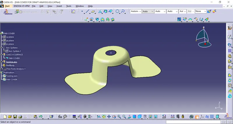
- In the above image, we saw that surface has a hole at the top & cuts at the side.
- From X direction as tooling axis, it increases the cost for mold due to a hole on the top to the required side core.
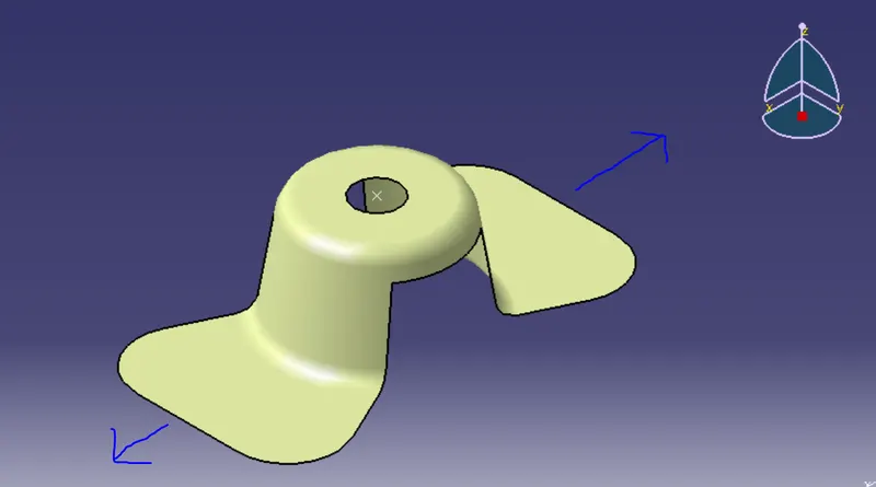
- From Y direction as tooling axis side core for the top hole is also not required
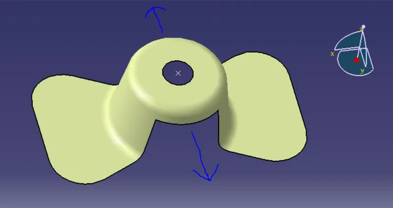
- Z-direction as tooling axis to clear this hole in tooling.
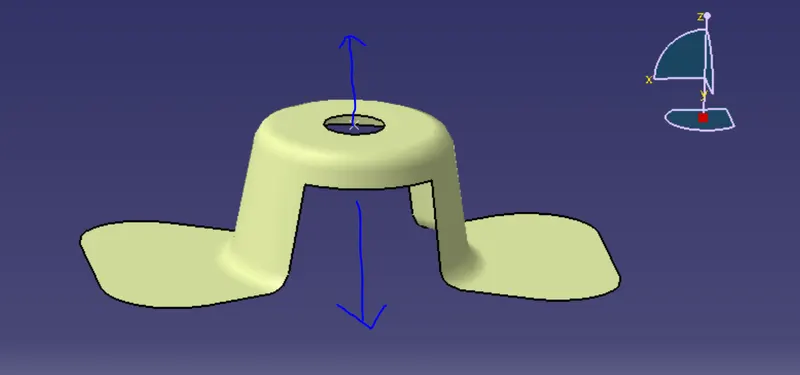
Now using the bisecting method to find the real axis of tooling.
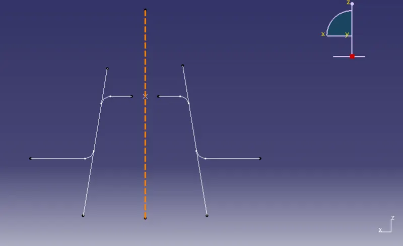
Insert axis system, we need to take the intersection of ZX plane with class A surface to get two curves on below image.
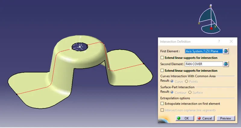
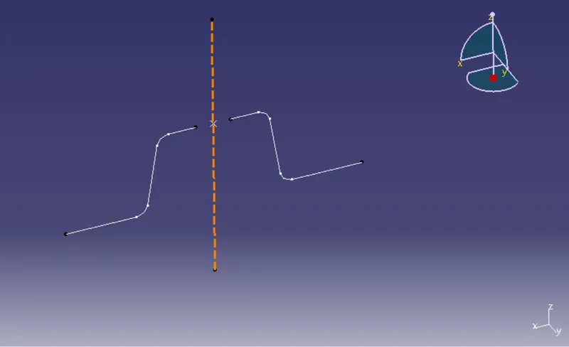
now we have to see which surface will create a problem for tooling difficult.
so we have to check the surface lying parallel to the tooling axis direction. make a line along parallel using point to point direction, here we get two lines, now bisect the lings and choose the vertical direction, this will be our tooling axis for X direction.
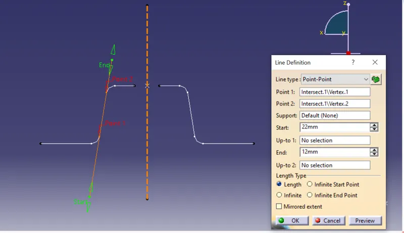
- same we intersect the YZ plane of the axis with class A surface & repeat the same procedure again.
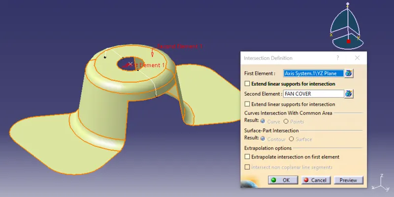
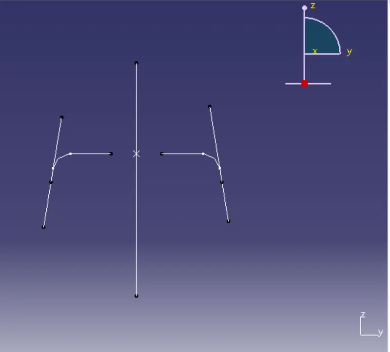
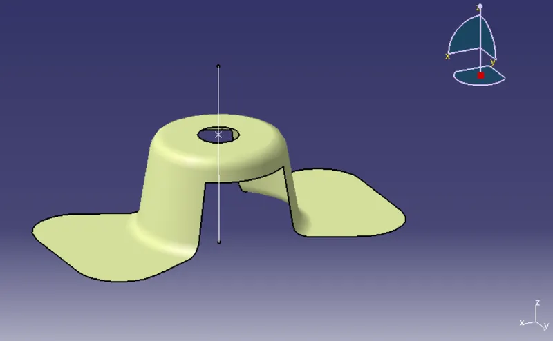
Now we have the X-axis and Y-axis. now we bisecting the two-axis to get the final tooling axis
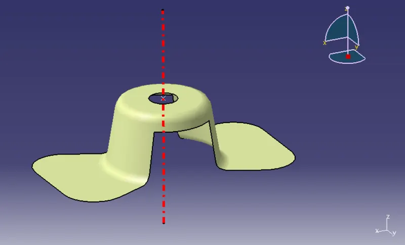
3) PUBLICATION:
before starting the draft analysis we publication the final tooling axis and class-A surface to make it easier to find.
select final tooling axis + class A surface and go to
TOOLS > PUBLICATION
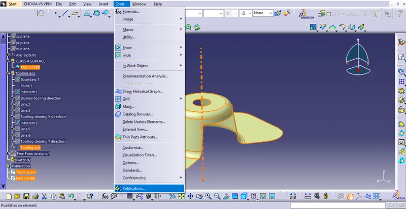
Draft analysis:
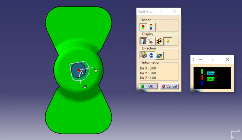
1) perform draft analysis Go to Insert > analysis > feature draft analysis.
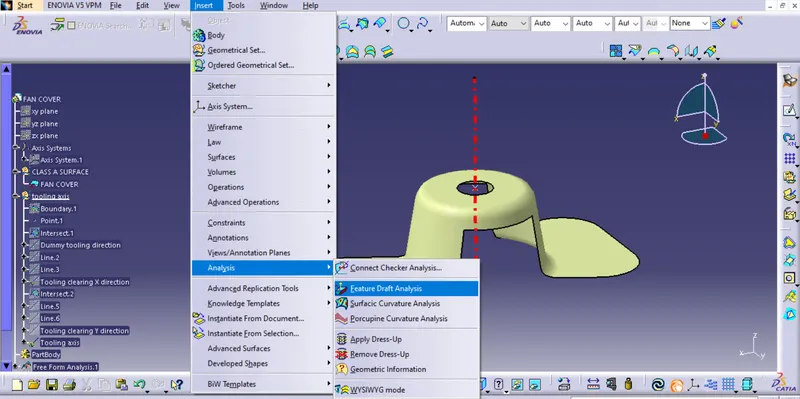
2) add the material in parameter mode.
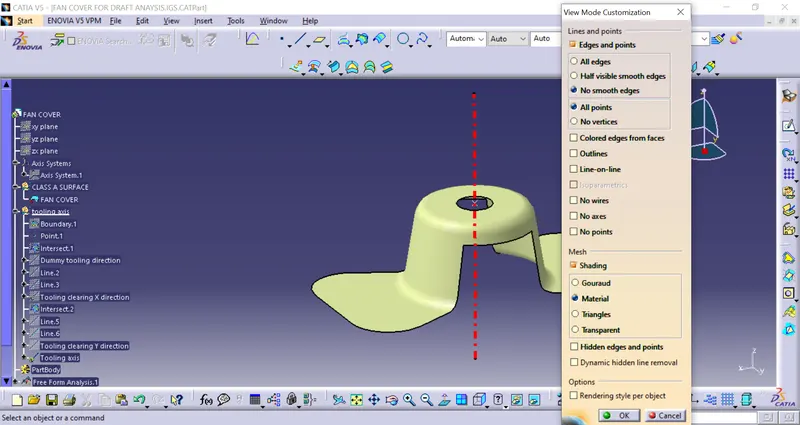
3) Click on the compass icon & align with the tooling axis
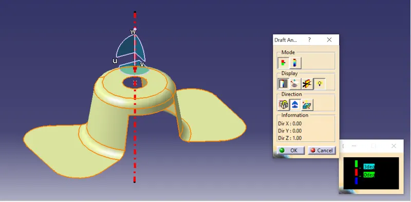
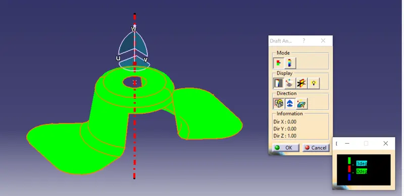
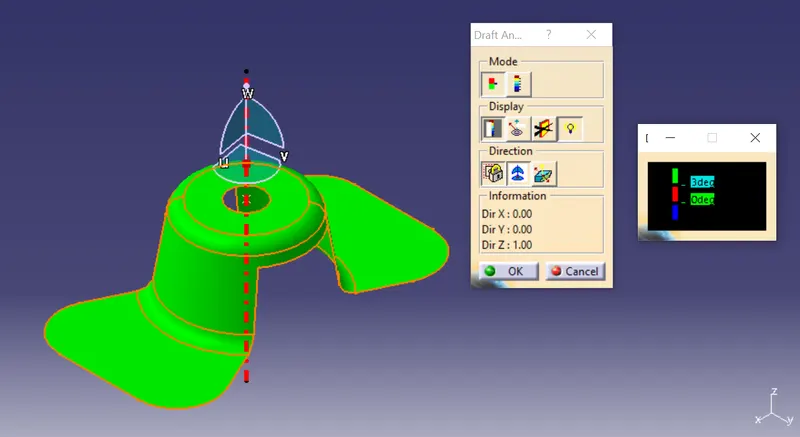
- from the above image, we see surface in green color has more than a 3degree draft which is required for tooling feasibility
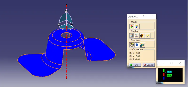
- by inverting the draft direction it shows a blue color.
- the below image is full analysis mode.
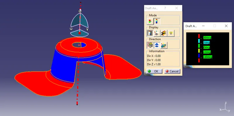
- The below image is analysis under running point to see the angle of the surface
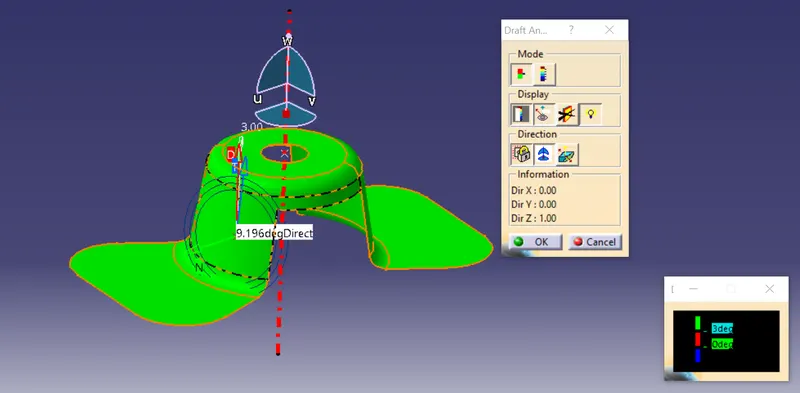
The draft angle in various orientations (Isometric, front , side and Top view)
ISOMETRIC View:
FRONT view:
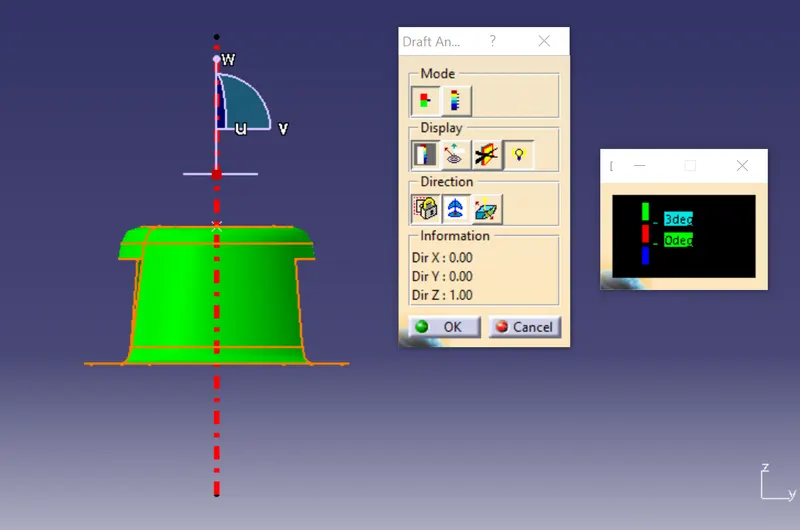
SIDE view:
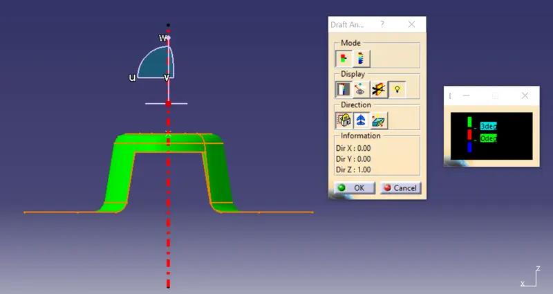
TOP view:
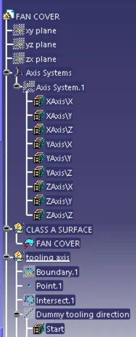
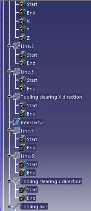
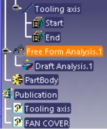
Images of a Tree structure: