Week 8 - Challenge 2 - Base Bracket Design
AIM:
Creating the Base Bracket Plastic component through the given Class-A surface, and performing the draft analysis on the model.
OBJECTIVE:
The objective of the challenge is to create a base bracket design along the solid part body from class A surface in CATIA surface workbench and part design.
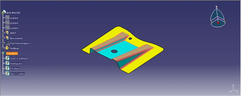
1. INPUT CLASS A SURFACE:
2. Draft analysis on the class-A surface:
- First, change the parameter to material mode and then go to perform draft analysis Go to Insert > analysis > feature draft analysis.
- Click on the compass icon & align with the tooling axis.
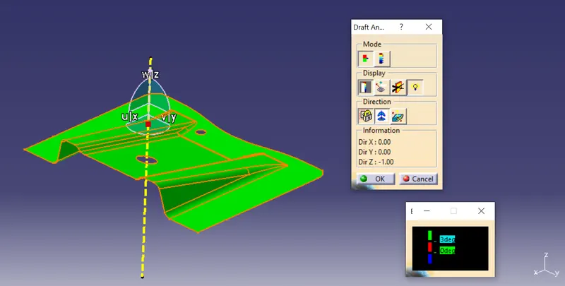
- from the above image, we see surface in green color has more than a 3degree draft which is required for tooling feasibility
3. Tooling axis direction:
The Tooling Direction is basically the direction that the mold pulls apart. The mold is built in two separate pieces, basically. You have a Cavity side and you have the Core side. The Core pulls apart from the Cavity and that's the Dyeline or the Tooling Direction.
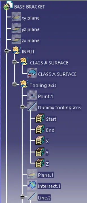
- analyzing the model visually to see the most efficient side suitable for the tooling axis from the image below image.
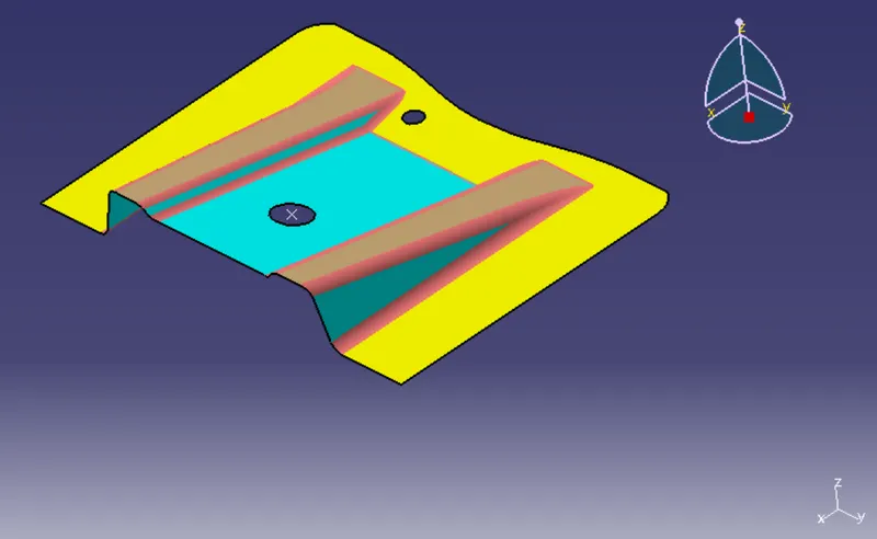
- first, we need to create a point mid between the circle from the above image to make a center.
- then place a line of dummy axis in the point from the below image.
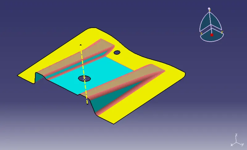
- after inserting the dummy axis we insert a plane with respect to the YZ plane to intersection the boundary from the below image.
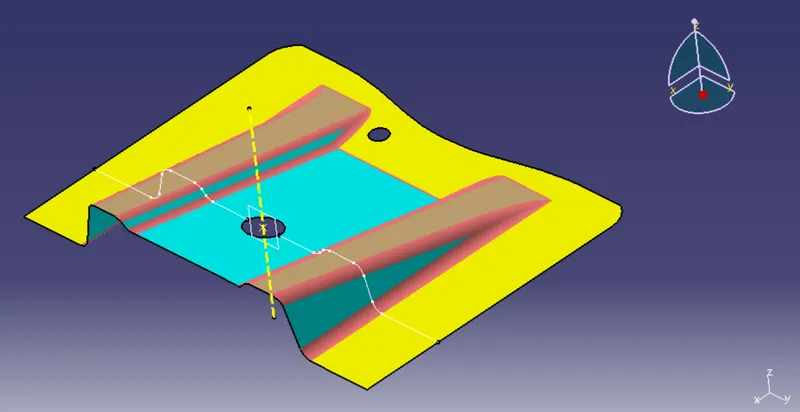
- so we have to check the surface lying parallel to the tooling axis direction. make a line along parallel using point to point direction, here we get two lines, now bisect the lings and choose the vertical direction, this will be our tooling axis for Z direction.
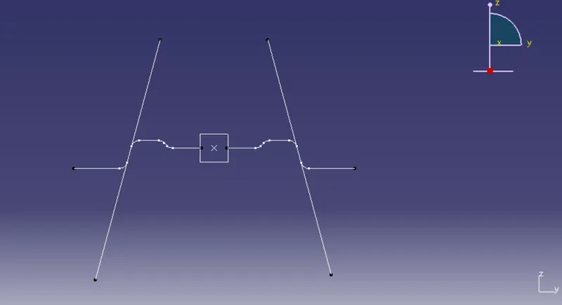
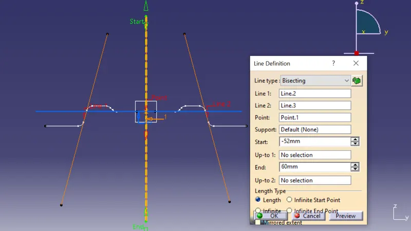
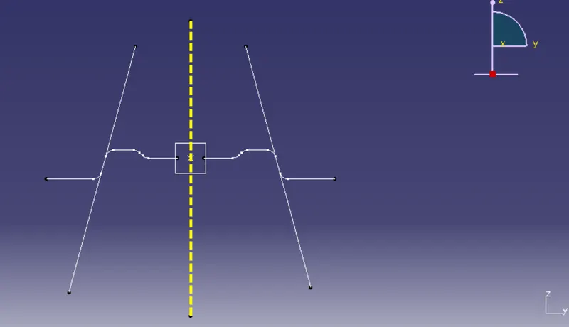
- after creating the tooling axis we need to create a class B surface.
4. Class-B surface:
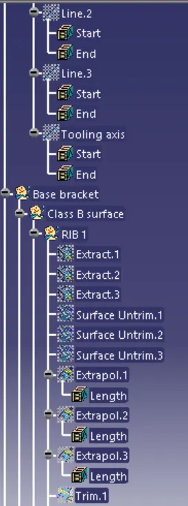
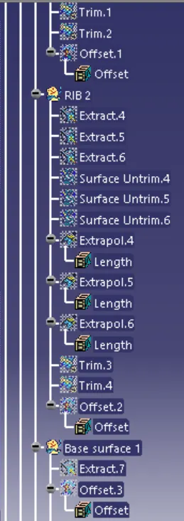
- we take the extract of the right and left side RIB from class A surface to offset by 2.5mm as shown below image.
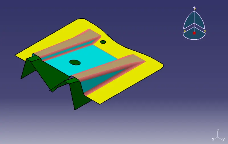
- after we complete the RIB we need to extract the outer surface and extrapolate the surface.
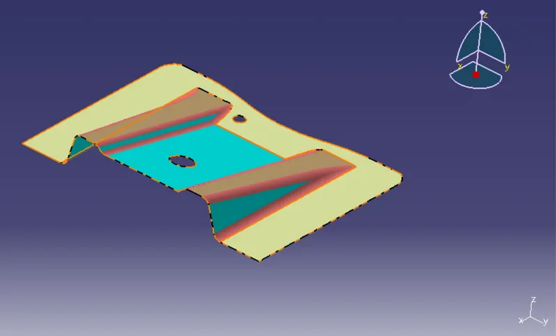
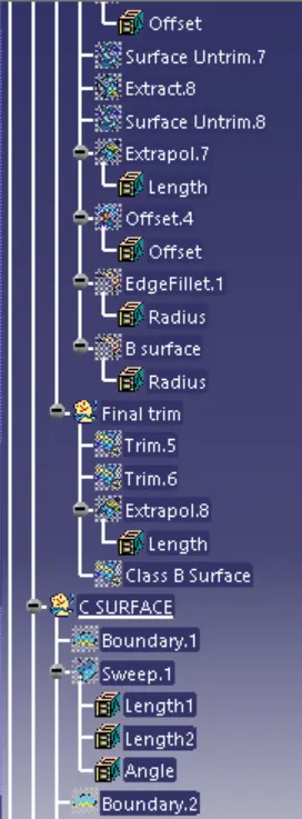
- after extrapolate the surface offset the surface by 2.5mm and trim with ribs to form a Class B surface.
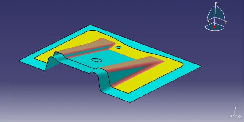
5. Class-C surface:
The surface will be created using the sweep command by sweeping the boundary of Class-A surface along the tooling axis along the A-B surface is known as CLASS-C surface.
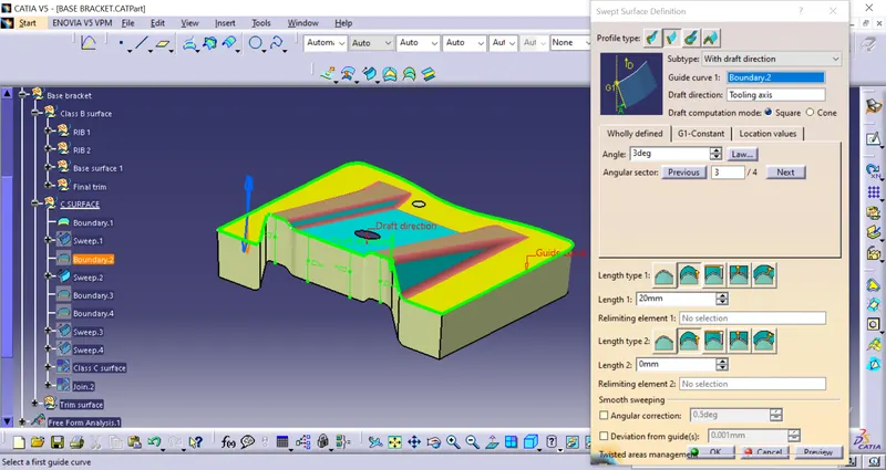
after creating a Class-C surface using the B and C surface created a closed surface will be formed by using trim commend.
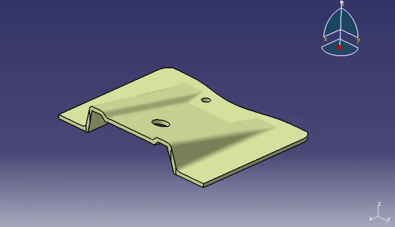
- After creating the closed surface go to the part workbench to form a solid part from the closed surface using close surface commend.
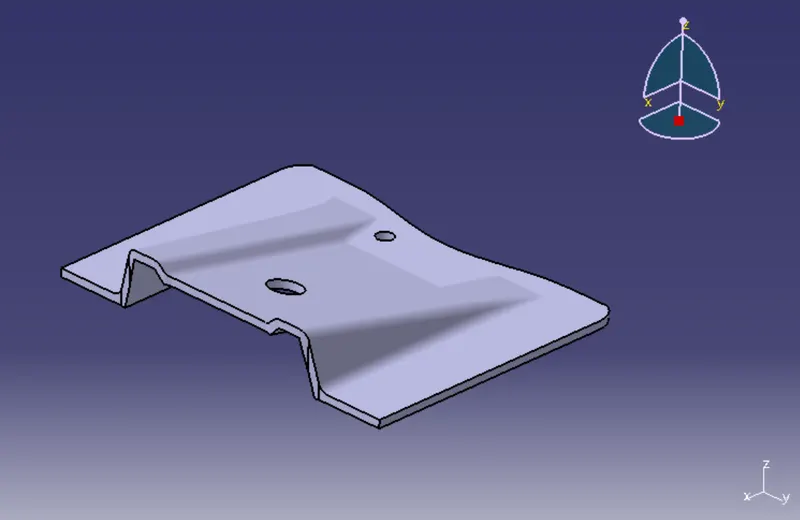
6. Drafting analysis on solid part body:
- After creating the solid body again I will perform the draft analysis but this time the whole part body.
- I follow the same process I do on the class-A surface.
- First, change the parameter to material mode and then go to perform draft analysis Go to Insert > analysis > feature draft analysis.
- Click on the compass icon & align with the tooling axis.
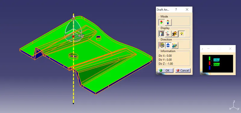
- from the above image, we see the surface in green color has more than a 2-degree draft which is required for tooling feasibility.
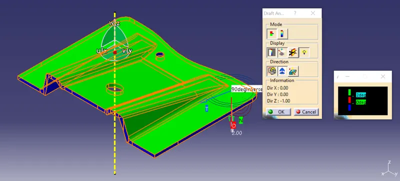
- The below image is analyzed under running point to see the angle of the surface.
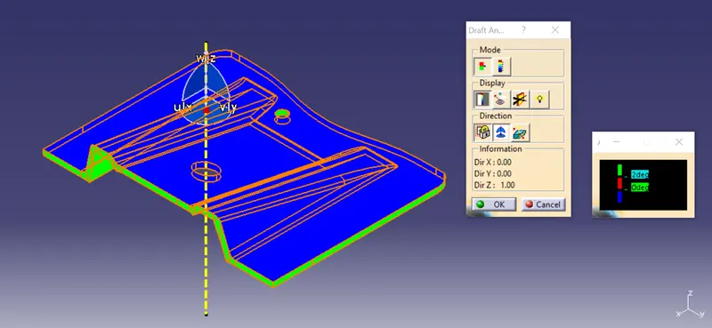
- by inverting the draft direction it shows a blue color.
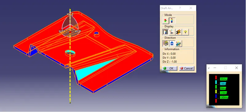
- the below image is full analysis mode.
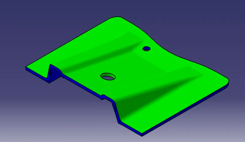
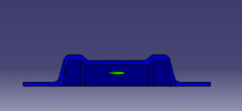
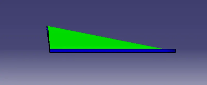
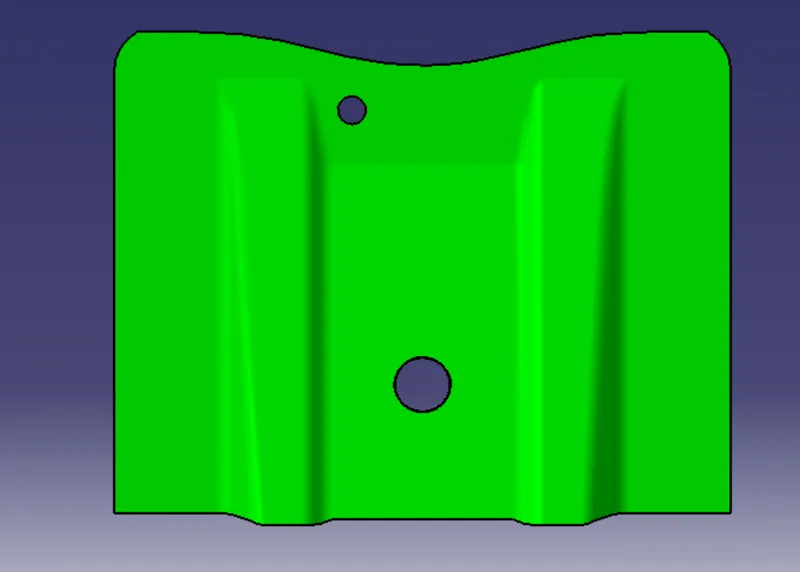
various orientations (Isometric, Front, Side, and Top View)
ISOMETRIC VIEW
FRONT VIEW
SIDE VIEW
TOP VIEW
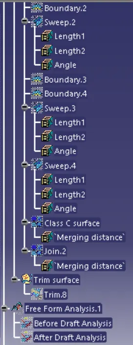
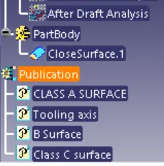
Tree Structure