Week 8 - Challenge 3 - Switch Bezel Design
AIM:
Creating the Switch Bezel Plastic component through the given Class-A surface and perform draft analysis on the model.
OBJECTIVE:
The objective of the challenge is to create a Switch Bezel Plastic design along the solid part body from class A surface in CATIA surface workbench and part design.
- To create a class B & C surface for the given component.
- To form a tooling axis.
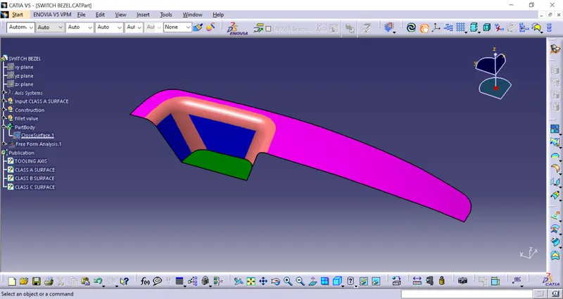
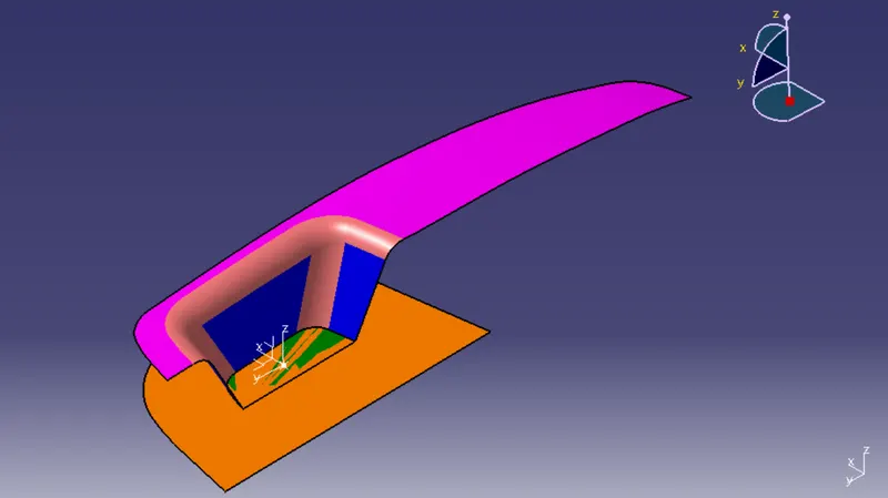
1. INPUT CLASS A SURFACE:
2. TOOLING AXIS DIRECTION:
The Tooling Direction is basically the direction that the mold pulls apart. The mold is built in two separate pieces, basically. You have a Cavity side and you have the Core side. The Core pulls apart from the Cavity and that's the Dyeline or the Tooling Direction.
- analyzing the model visually to see the most efficient side suitable for the tooling axis from the image below image.
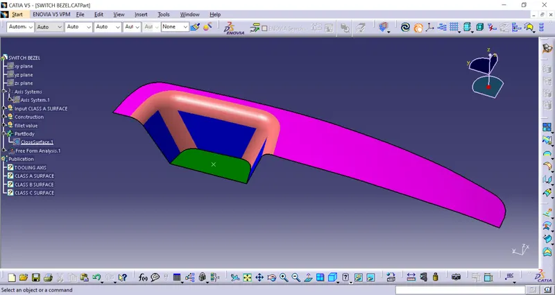
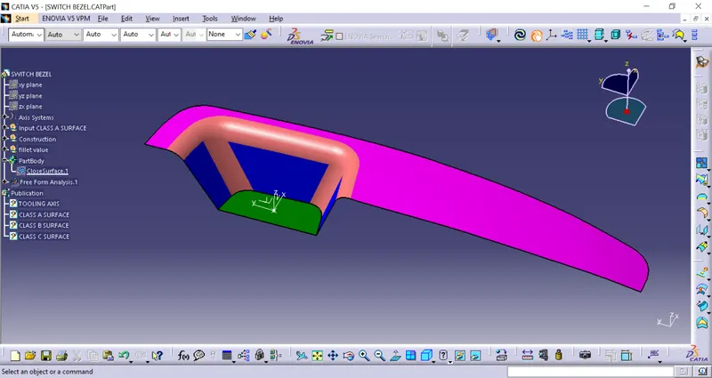
- Insert an axis on the point to further tooling axis creation.
- we need to take the sketch of the ZY plane with class A surface to get two curves on the below image.
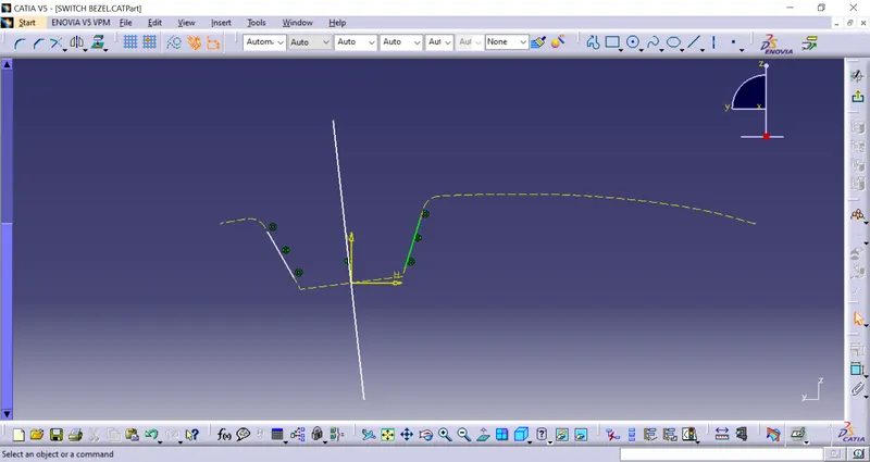
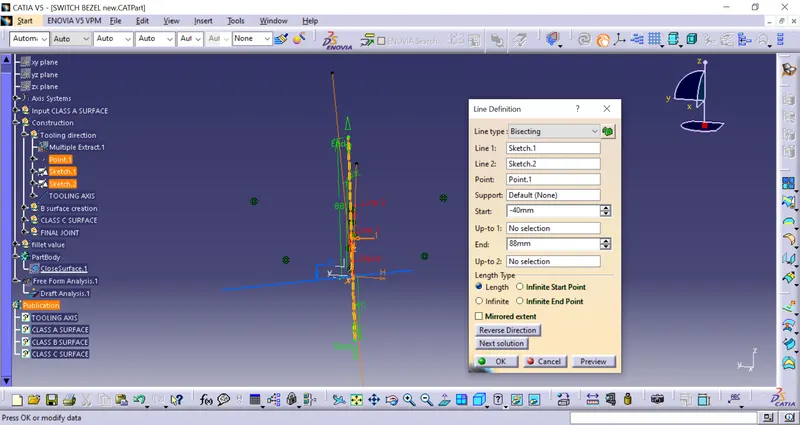
- make a line along parallel using point to point direction, here we get two lines, now bisect the line and choose the vertical direction, this will be our temporary tooling axis.
- we need to take the sketch of the ZX plane with class A surface to get curves on the below image.
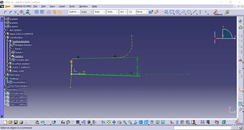
- After we need to find the real tooling axis from the two temporary axis by using the bisecting line.
3. Class-B surface:
- To start with Class-A top surface is extracted and untrimmed.
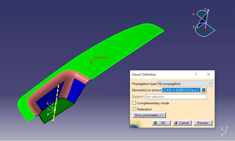
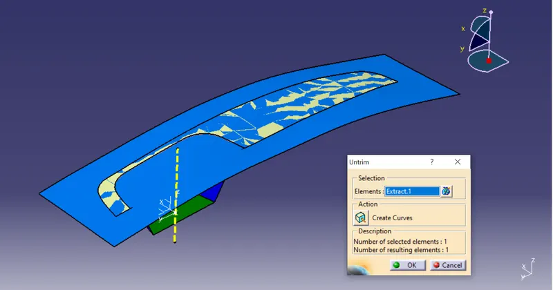
- likewise, the surface of the Class-A walls are extracted>Untrim>Extrapolate>trim.
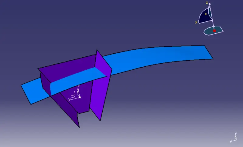
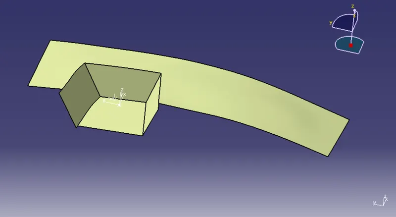
- once all the surfaces of class-A are taken and trimmed they are formed into a bezel surface.
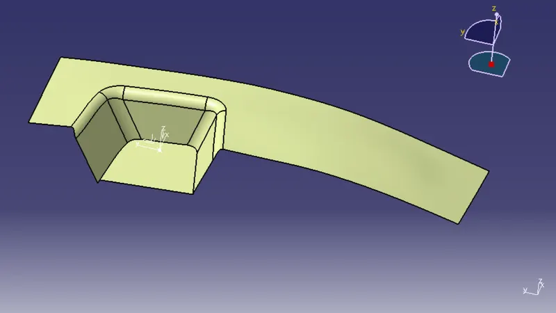
- As per the requirements, the radius value will be calculated from the offset distance of 3mm thickness will be added. After adding the radius value to form the Class-B surface
4. Class-C surface:
Now taking the boundary from the class-A surface and smoother the curve to avoid multiple sections.
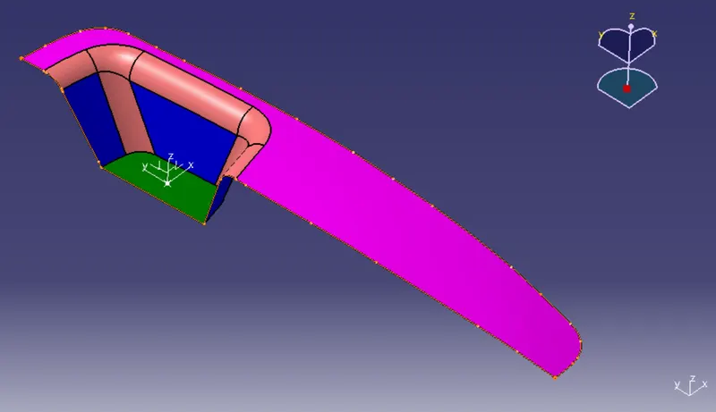
- after taking the Boundary to sweep the boundary to form a Class-C surface.
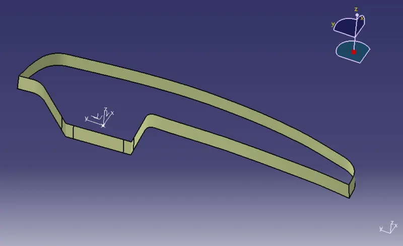
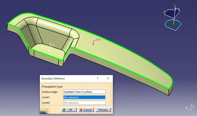
- After Forming the Class-B & Class-C surfaces trimmed and check for any discontinuity on the boundary.
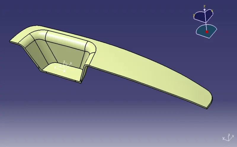
- After trimming the Switch Bezel surface will look like.
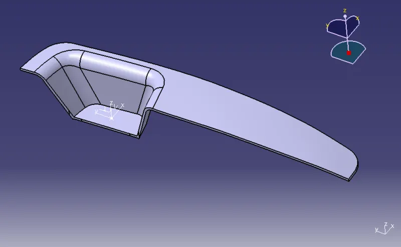
- The solid form of Class-A, B & C surface.
5. Drafting analysis on the solid part body:
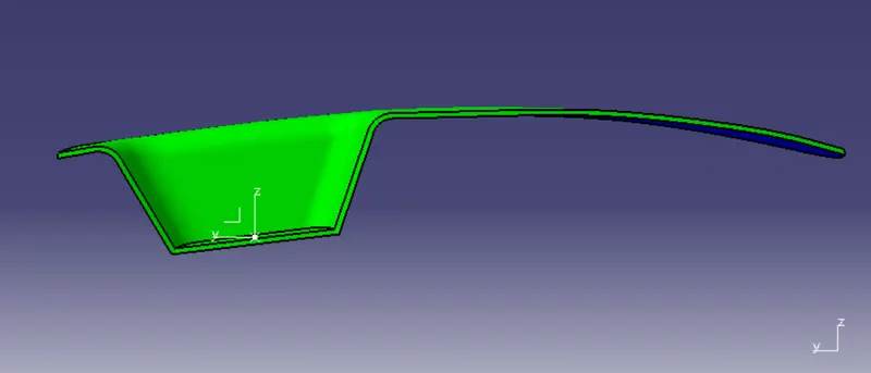
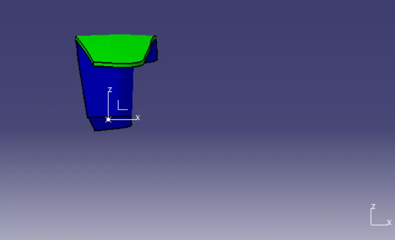
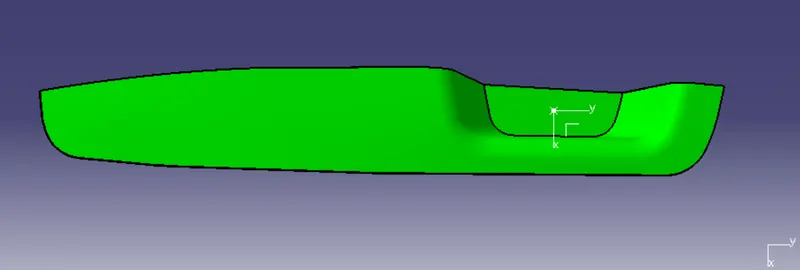
- After creating the solid body we will perform the draft analysis of the whole part body.
- First, change the parameter to material mode and then go to perform draft analysis Go to Insert > analysis > feature draft analysis.
- Click on the compass icon & align with the tooling axis.
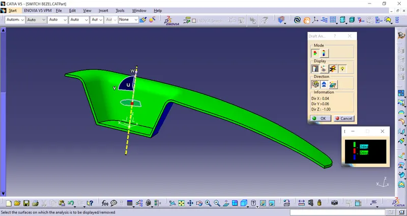
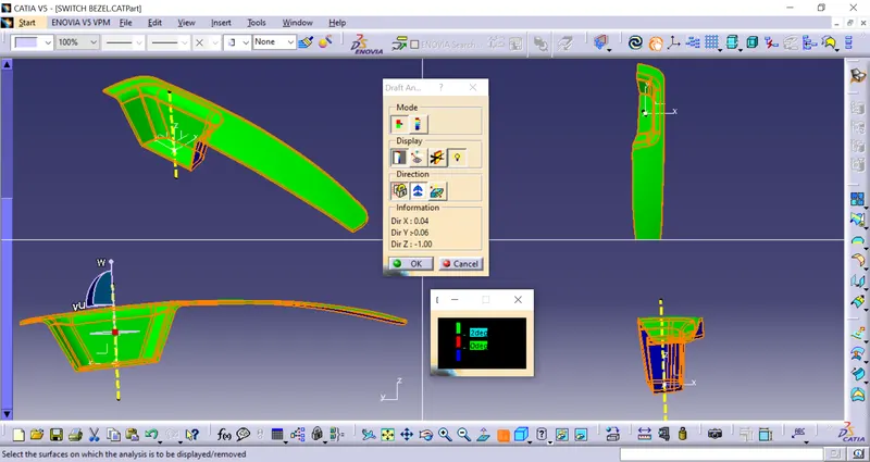
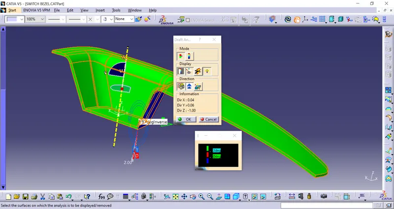
- The below image is analyzed under the running point to see the angle of the surface.
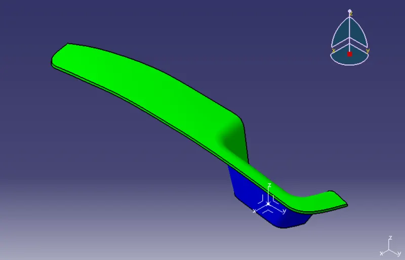
various orientations (Isometric, Front, Side, and Top View)
ISOMETRIC VIEW
FRONT VIEW
SIDE VIEW
TOP VIEW
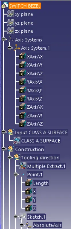
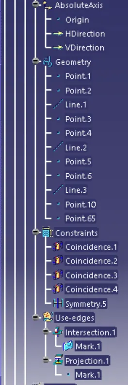
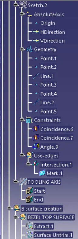
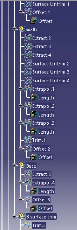
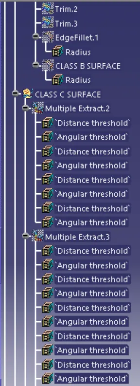
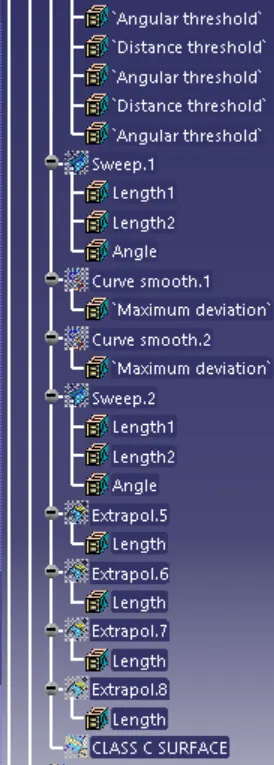
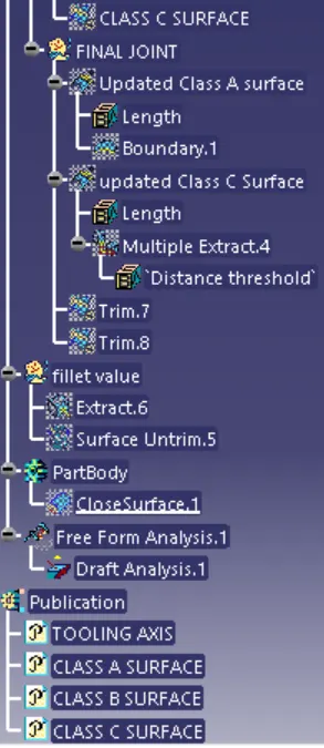
TREE STRUCTURE: