Photo Realistic Rendering
MODELLING OF AMERICAN CHOPPER IN SOLIDWORKS
INTRODUCTION
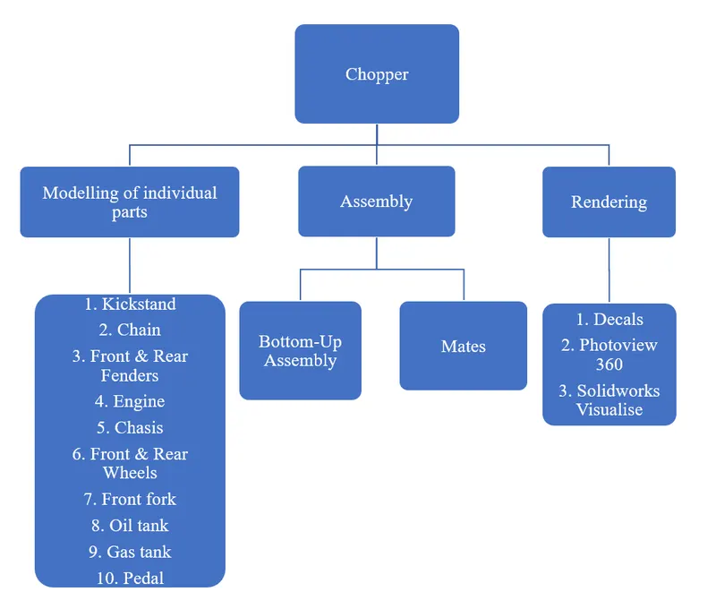
In this project, we are to learn the entire modeling of an American chopper on solid works. This software is mainly used to model 3D parts using 2D sketches. It also has material appearances look for the model which we create and apply the exact material for each of the parts individually after with help of photoview360 Add-in the final model to make it look photorealistic. In this project, we learned about the detailed design of American chopper parts, Assembly, and rendering.
OBJECTIVE:
The main objectives of this project are:
- To create individual parts of the chopper.
- To assemble all the individual parts to the chopper.
- To know the application of decals, lights, and cameras.
- To create a photorealistic model by rendering using photoview 360 and SolidWorks Visualize.
Design Methodology/Approach:
Kickstand:
It allows the bike to be kept upright without leaning against another object. It is used to
support the chopper while it rests on the ground.
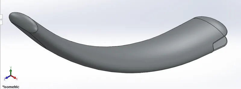
Features used to create Kickstand:
- Sketch
- Loft
- Dome
- Extrude boss
- Extrude cut
- Fillet
- Split
Sketch:
The sketch is a basis for a 3D model. Sketch entities tools are line, arc, circle, ellipse, splines, etc.
Loft:
The loft feature is used to create complex geometry. Only the first and last profiles can be points it including guided curves to create a single 3D model.
Dome:
This feature is used on faces majorly. You can apply dome to faces whose centroid lies
outside the face. It allows applying dome for irregular shapes.
Extrude boss:
It converts 2D sketches into 3D models.
Extrude cut:
This feature is used to remove materials for single and both directions.
Fillet:
This feature converts internal and external faces into rounded. E.g.- face, edge etc.
Split:
This feature is used to split faces on multiple bodies on other surfaces.
Chain:
Chain drive most used for transmission of mechanical power in Motorcycles
it transmits power from the Engine to the Rear wheel.
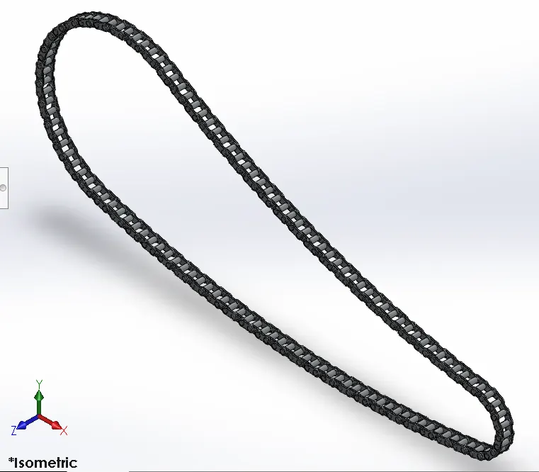
Features used to create Chain:
- Sketch
- Trim
- Fillet
- Blocks
- Extrude
- Patterns
Trim entities:
Power trim - You can use Power trim to trim multiple, adjacent sketch entities by
dragging the pointer across each sketch entity. Trims open sketch entities outside
of two bounding entities.
Extend entities - You can use extend entities to extend sketch entities along with their
natural paths.
Blocks:
Drawing items and sketch entities that you use often, such as standard notes,
title blocks, label positions, you can save as Blocks.
- To create blocks Tools > Block > Make.
- You can save a selected sketch directly to a block file Tools > Blocks > Save.
Patterns:
- Linear sketch pattern - when you pattern one or more features along one or two linear paths on horizontal & vertical planes.
- Circular sketch pattern - when you pattern one or more features around an axis in circular type profiles.
Front & Rear Fenders:
Fenders are also known as “mudguards”.
Front fender – It is mounted on the front fork above the wheel. It helps protect your feet
and ankles from spray if you're riding in the rain or
even though a puddle.
Rear Fender - Will keep you from having a skunk stripe on your backside if you ride in
the rain.
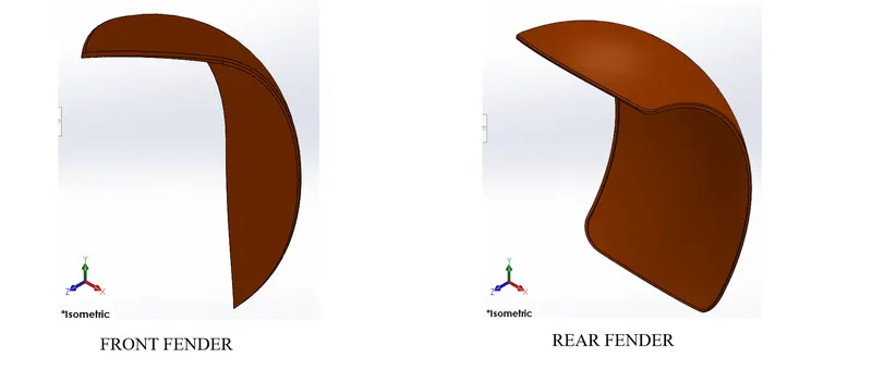
Features used to create Front & Rear Fender:
- Sketch
- Offset entities
- Trim entities
- Revolve
- Dynamic mirror
- Split
Revolve:
The revolving feature Creates a solid, a thin feature, or a surface.
Select an axis around which the feature revolves. This can be a centreline, line, or edge, depending on the type of revolving feature you create.
Dynamic mirror:
It is used to sketch the entities that are mirrored about the pre-sketched entities.
Engine:
An engine or motor is a machine designed to convert one or more forms of energy into
mechanical energy, in this model we used a V-twin engine. Providing them with an
attractive "burbling" exhaust sound at the expense of uneven power delivery makes the
motorbike less stable through fast corners. V-twin provides your bike with an sample
amount of torque and a broad powerband.
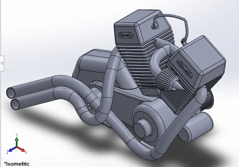
Features used to create Engine:
- Sketch
- Trim
- Revolve
- Boss extrude
- Extrude cut
- Offset
- Dome
- Fillet
- Projected curves
- Composite curves
- Sweep
- Mirror
- Circular pattern
- Split
Offset:
You can offset sketch entities, lines, spline, arc, model edges by a specified distance.
Projected curves:
The projected curve is a kind of 3D curve projected based on two different 2D sketches
from different planes.
Composite curves:
It is used to combine two different curves into a single curve.
Sweep:
The sweep feature creates a shape by moving a 2D sketch along with a profile to form a 3D
model.
Mirror:
Mirroring is another way that SolidWorks can create a “copy” of an existing object.
Additionally, you must choose a plane to mirror parts. In most cases, you will have to
create your own plane to have the mirror done the way you need.
Chassis:
A chassis is a load-bearing framework on which the body is supported. It carries the
the whole weight of the bike parts to carry.
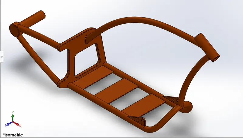
Features used to create Chassis:
- Sketch
- Offset
- Convert entities
- Projected curves
- Trim
- Split
- Mirror
- Sweep
- Revolve
- Cut extrude
- Fillet
- Combine
Convert entities:
Whenever we need to make a sketch entity that matches other geometry of our model
we can use the Convert Entities tool.
Combine:
This feature is used to combine the two solid bodies into a single body like add, subtract,
etc.
Front & Rear wheel:
A wheel is a circular component made up of hard material, covered with rubber tires.
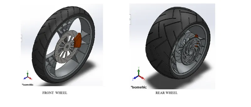
Features used to create Front & Rear wheel:
- Sketch
- Revolve
- Trim
- Fillet
- Boss extrude
- Revolve cut
- Linear pattern
- Chamfer
- Cut extrude
- Circular pattern
- Planes
Front Fork:
A motorcycle fork connects a motorcycle's front wheel and axle to its frame, typically via a yoke, also known as a triple clamp, which consists of an upper yoke joined to a lower yoke via a steering stem, a shaft that runs through the steering head, creating the steering axis.
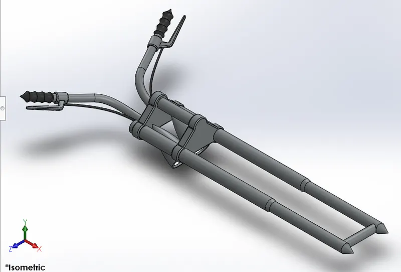
Features used to create a Front fork:
- Sketch
- Extrude
- Trim
- Revolve
- Split
- Move/copy bodies
- Dome
- Mirror
- Combine
- Projected curve
- Sweep
Oil tank:
The oil tank is used to store the oil required to run the Engine. The thickness of the oil tank is 3mm.
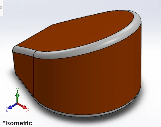
Features used to create an oil tank:
- Sketch
- Boss extrude
- Combine
- Fillet
- Shell
SHELL:
Shell feature is used to define the thickness of the element/surface.
Gas tank:
A fuel tank is a safe container for flammable fluids. Though any storage tank for fuel may be so-called, the term is typically applied to part of an engine system in which the fuel is stored and propelled into an engine.
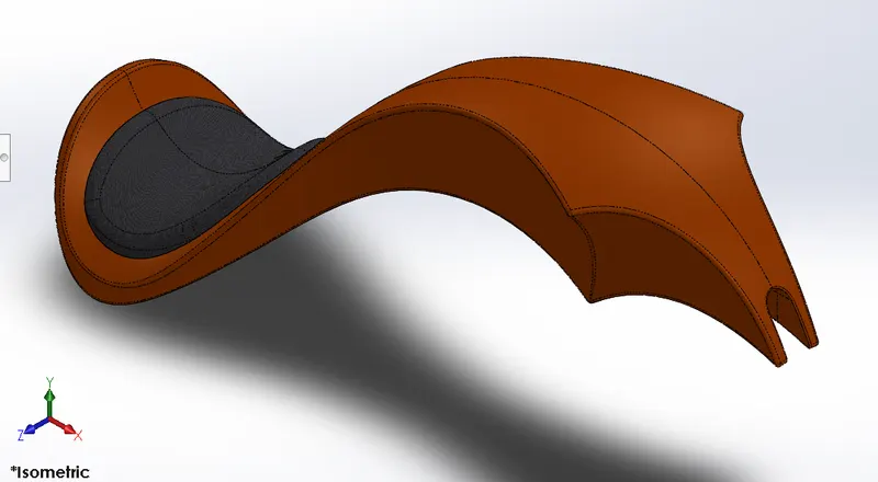
Features used to create a Gas tank:
- Sketch
- Trim
- Projected curves
- Sweep surface
- Loft surface
- Fill surface
- Surface trim
- Surface knit
- Sweep cut
- Fillet
Loft surface:
Loft Surfaces are surfaces generated by multiple 3D Curves or existing edges creating a smooth tangency between the selected curves. Match Points are created between each selection denoting the orientation and path of the loft surface.
Sweep surface:
Sweep by Two Guide Curves is defined as moving and adjusting a section curve along two guide curves
Fill surfaces:
The Filled Surface feature constructs a surface patch with any number of sides, within a boundary defined by existing model edges, sketches, or curves.
Surface trim:
Create two or more surfaces that intersect at one or more points or create a surface that intersects with a plane or has a sketch on its face. Then surface trim will remove the surface that doesn’t we need.
Surface knit:
The Knit surface is the most used feature in creating a solid body in SOLIDWORKS. It is a tool that can combine two or more surfaces into a single one.
Pedal:
The pedal is an external part attached to the chassis. It comforts the rider to place a leg on it.
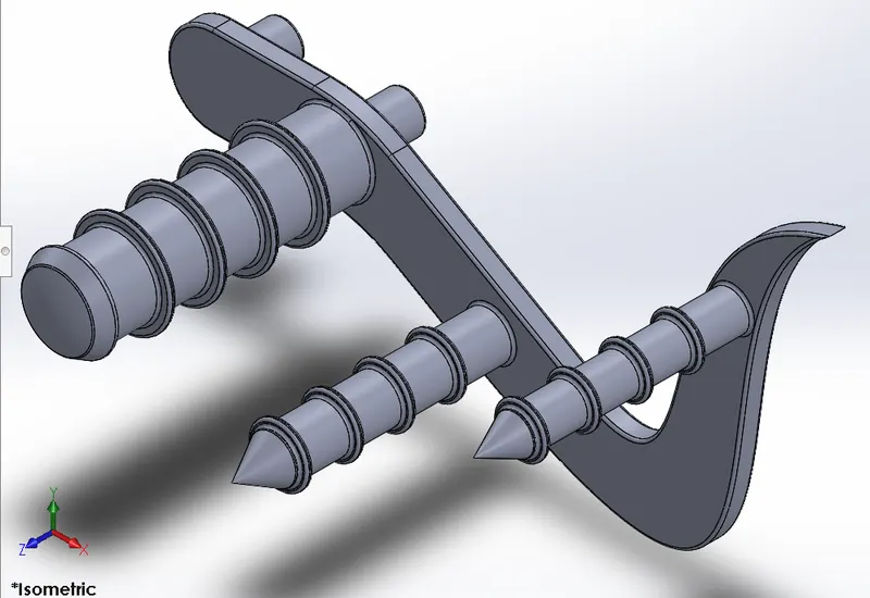
Features used to create a pedal:
- Sketch
- Extrude
- Fillet
- Linear pattern
- Dome
- Chamfer
Chamfer:
Chamfering is the process to remove material by a 45-degree angle to remove a 90-degree edge to make a slope.
Assembly of the chopper:
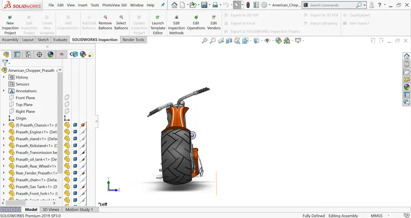
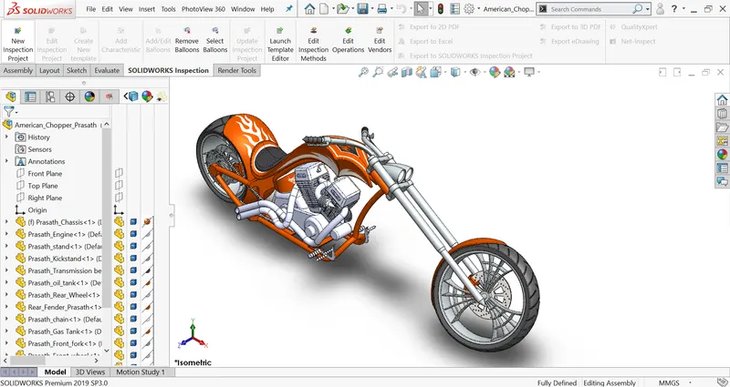
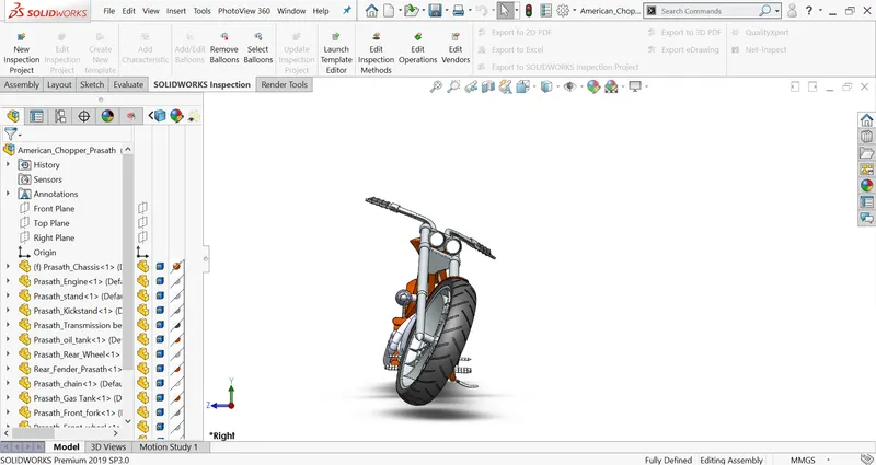
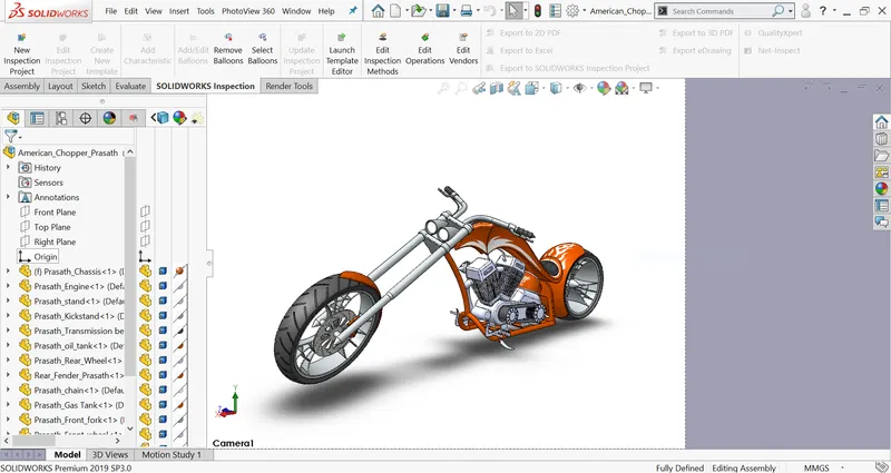
- In this model, we used the Bottom-up assembly approach to assembly the whole chopper by inserting parts and using mates to position the parts. To change the parts, you must edit them individually. These changes are then seen in the assembly.
- Initially, the chassis part is inserted in the assembly by using insert parts in the option and clicking ok to fix the chassis.
- After those other parts of the chopper are inserted into the assembly and given possible mate conditions.
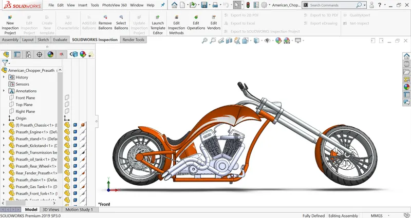
Features used to assemble chopper:
- Inserting parts
- Mates
Mates:
Mates create geometric relationships between assembly components. As you add mates, you define the allowable directions of linear or rotational motion of the components. You can move a component within its degrees of freedom, visualizing the assembly's behavior.
Rendering:
- Rendering is the process of generating a photorealistic image of a 2D or 3D model by using rendering.
- Rendering is done by two was in Solidworks.
- Photoview 360
- Solidworks visualize
Photoview 360:
It is an add-on in SolidWorks that produces photorealistic rendering images based on appearances. We edit appearances lights, color, material, decades, and camera.
With a model open, click Tools > Add-In and add in PhotoView 360.
Then go to render tools and make the final rendering to process realistic images.
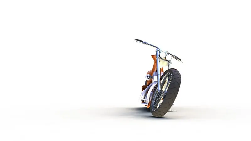
Right side view:
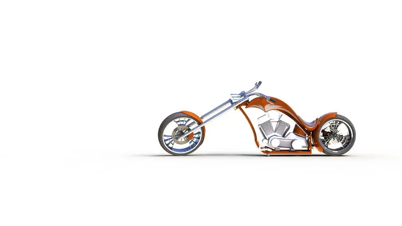
Backside view
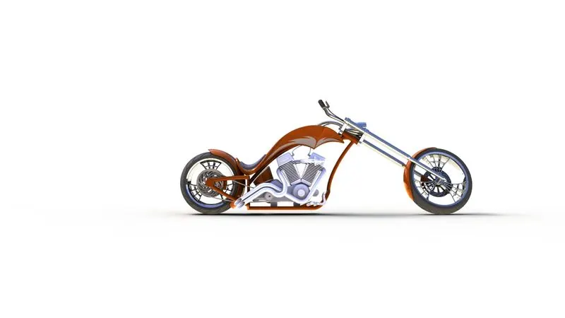
Front side view
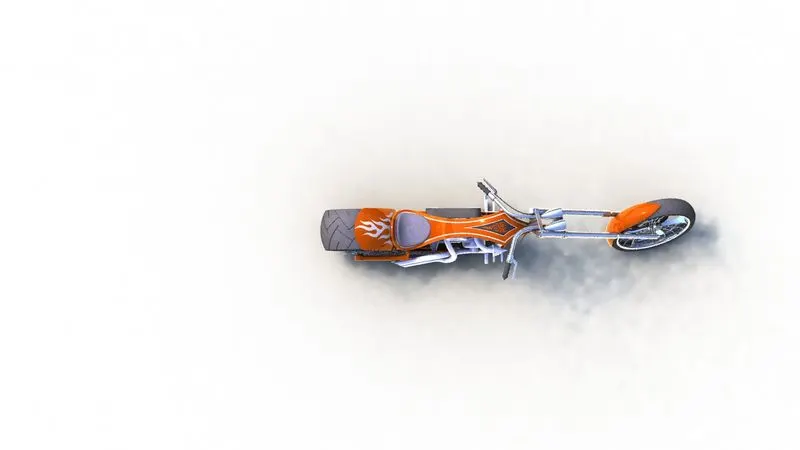
Top view
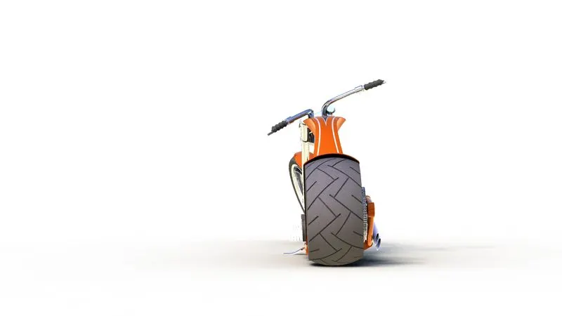
Left side view
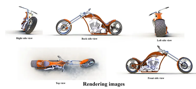
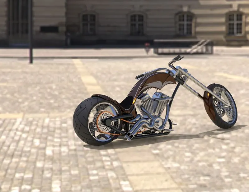
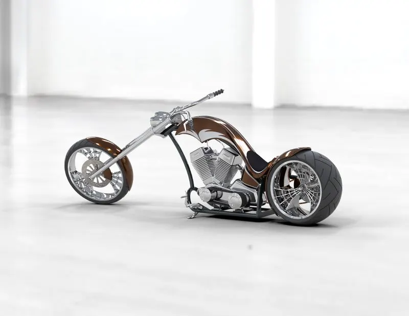
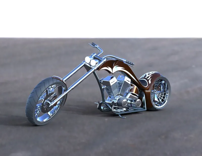
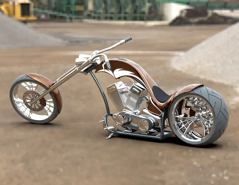
In the photorealistic model, some of the mate conditions and positions are changed due to rendering realistic models. Then the models are rendered into realistic images with different views.
Camera view:
You can modify unlocked camera views using View tools, with the lights and Camera Property Manager adding the camera.
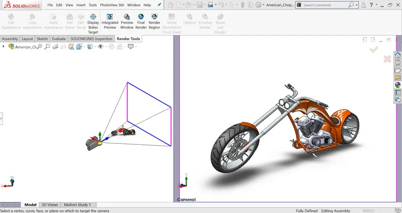
A camera edit screen appears to adjust the angle and view of the model on the left side screen. Check your results on the right pane of camera orientations...
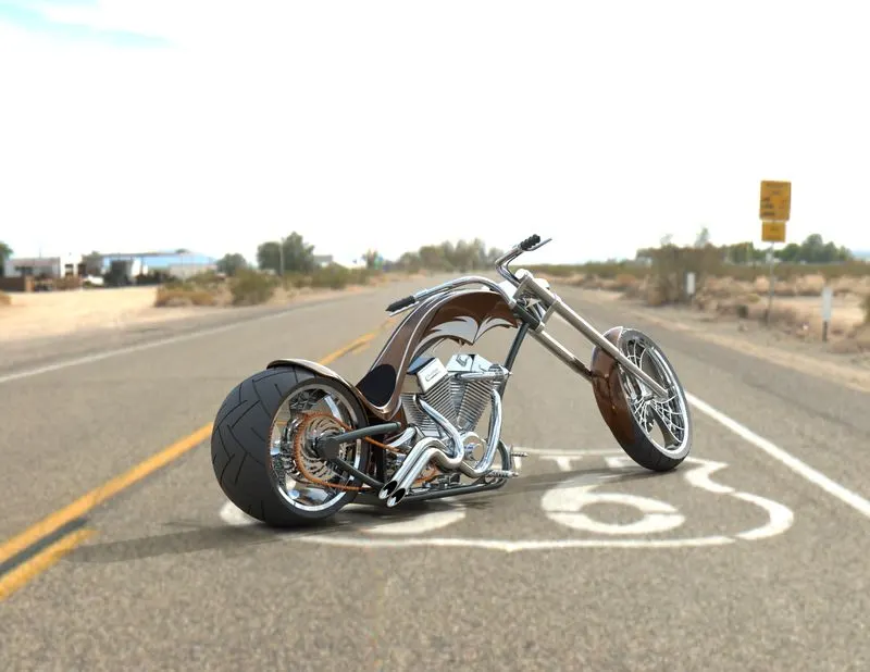
Solidworks visualize:
SOLIDWORKS Visualize Professional allows designers to tell a deeper 3D story about your product. SOLIDWORKS Visualize enables users to easily generate photo-quality stills and interactive animations to effectively communicate the most complex design details.
Conclusion:
- Knowledge learns about Solidworks features & tools to create 2D & 3D models.
- Gain knowledge of how to assemble the parts and approaches of the assembly.
- Learn about Solidworks visualize to render realistic images.