Week 8 - Challenge 4 - Bumper
Dear Sir,
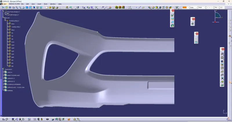
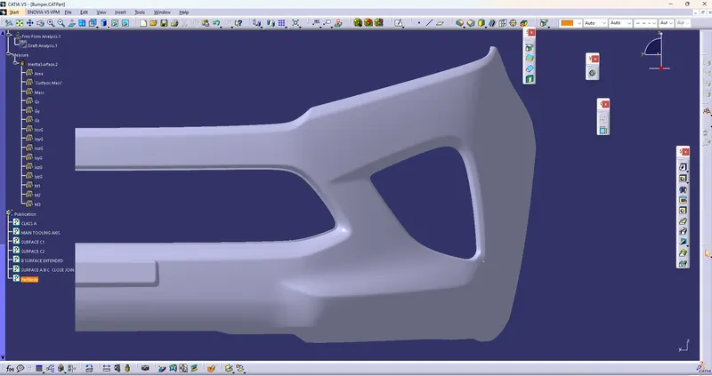
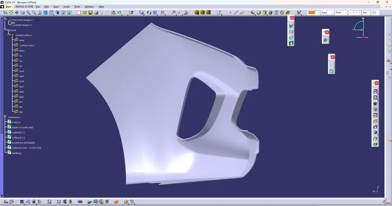
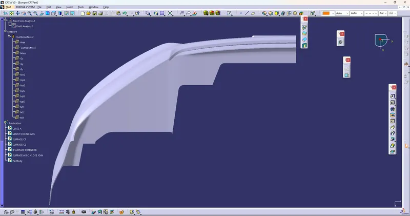
Please Find Challange Bumper.
Title of Project:- Creation of Bumper Body From Class A Surface
Inputs:- 1) Class A surface 2) Offset Thickness
Tools:- 1) CAD Software (Catia V5 )
Procedure:-
1) Establish Flow Work for Creating CAD Part
a) Door Trim
A) Input
i) Class A surface
ii) *Class A surface Repair (If any Flows or any uneven surface boundary)*
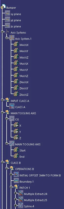
B) Main Tooling Axis
i) Support geometry
ii) Operations
iii) Tooling Axis
C) Class A surface Draft analysis
D) Class B surface
i) Support for B surface
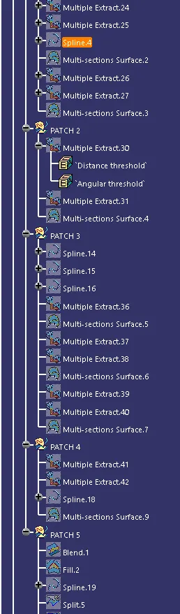
ii) Operations B surface
iii) Join B Surface
iv) B surface Check
E) Class C surface
i) Support for C surface
ii) Operations C surface
iii) Join C surface
iv) C surface Check
F) ABC Join Surface
i) Operations ABC Surface
ii) Join ABC Surface
iii) ABC Surface Check
G) Solid Body Creations
i) Draft analysis for Body
2) Get Input as Thickness for Body and Also Get Class A surface file
"Class A is Created by 3d Analysis or Scanning any Clay model ( Initial Shape design), so may there some uneven surfaces may form or any edge can create issue ".
3) Check Class A Surface Boundry check using Boundry Option.
a) Check All Points are connected together. (Also check for Multiple lines)
b) Any uneven or extra lines are created or overlap each other.
c) Discontinuity in between Boundry Lines
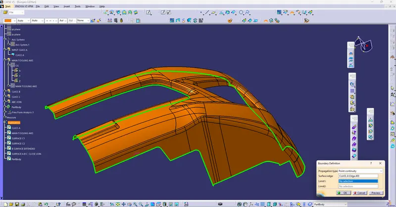
4) After ensuring Class A input is Okay, then Proceed further to Create Tooling axis. There are many types to create a Tooling axis for Class A surface.
a) Kept surface normal to All X, Y, and Z axis and Check maximum visibility of surfaces.
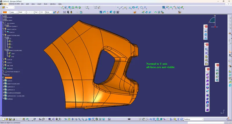
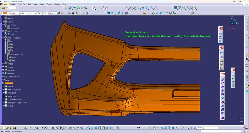
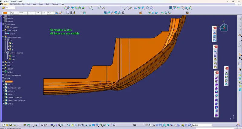
b) Create a Center of gravity point of the surface.
c) Create a Line Perpendicular to that view which shows maximum faces during normal view.
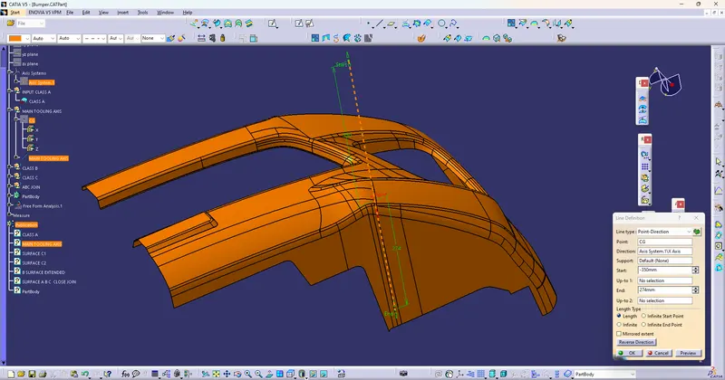
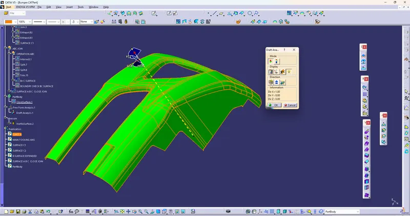
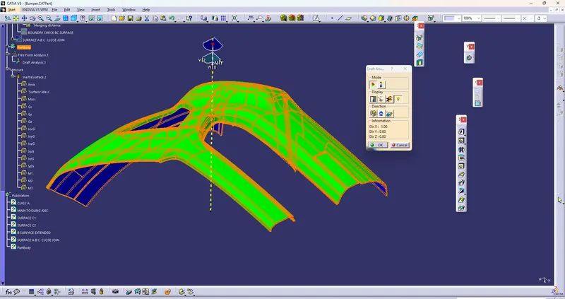
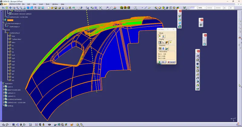
d) Perform Initial Draft analysis, kept conditions 0 deg and 3 deg, Use Compass direction and Drag compass and hold at Tooling axis. Generate Analysis and Note all Faces should be in Green Color, this shows Body is Passed and Tooling axis Created for Class is Correct.
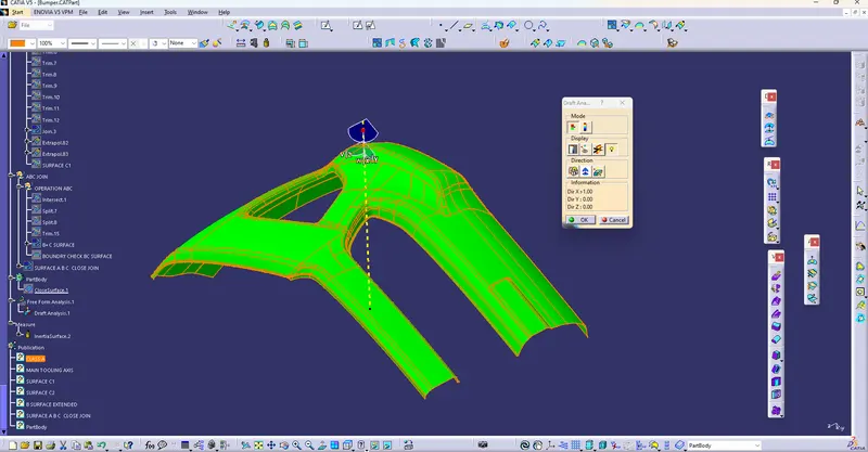
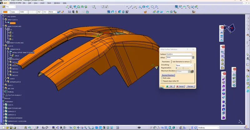
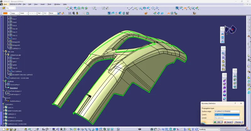
5) To create a B surface, There are several methods, but for continuous geometry use Direct Method. Create an offset of Class b Surace, notice some of the faces will create problems and keep vacant space there, To check all Patches, holes & gaps use the Boundry Option which helps to get all patches visible.
6) Repairing of All B surface Patches We can use Multiple methods but the most appropriate method is Multi-section, Which Helps To create a Surface using Boundaries and Support as an Offset B surface. Because this method involves Computrised Computation time this method directly will not work. to solve issues the following tips can be used during patch Repairing.
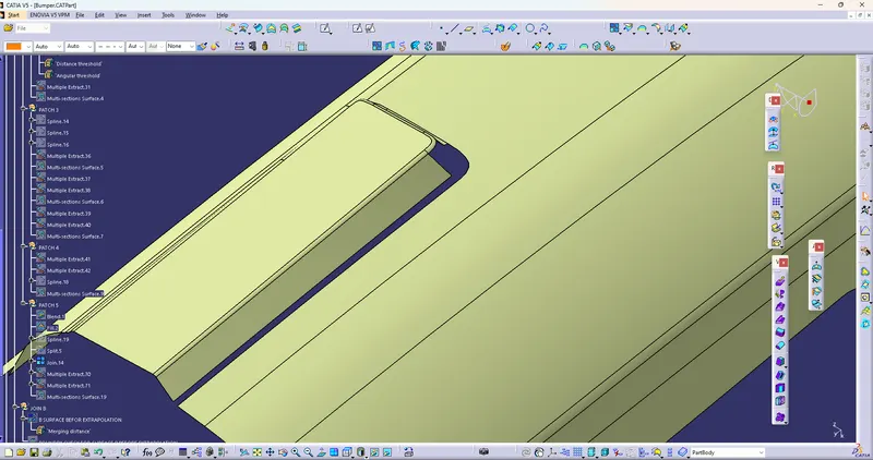
a) Delete neighboring attached surface and try again to make a Multi-section surface
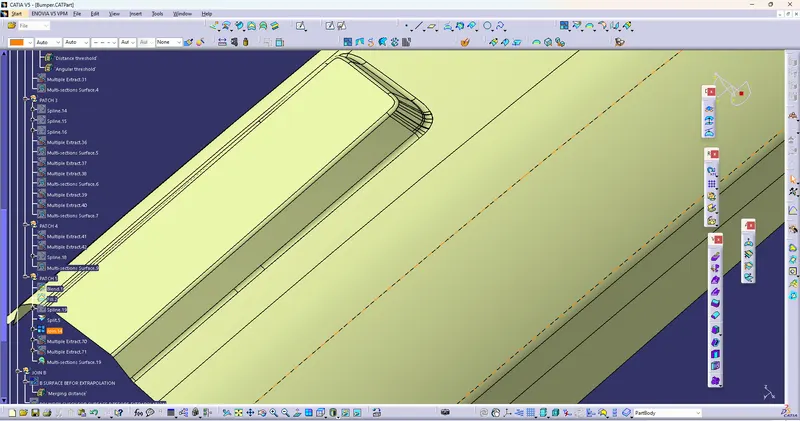
b) Simplication of Complex nearby surfaces.
c) Create Spline to ensure Curvature of the surface.
7) Join All Multi-section Surfaces and B surface Together
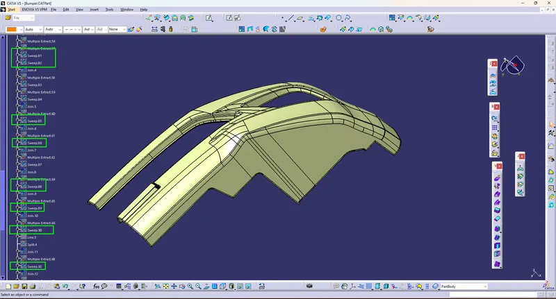
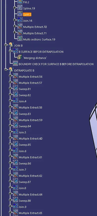
8) Use Extrapolate option or Sweep Command to extend B surface Boundary. For Extrapolation, We have to Perform operation for each edge with Tangent Continuity With No Propogation. in Sweep Command We can Extract Edges and By giving reference as offset b surface create a surface at 0 deg. (ensure tangency of the curve before using Sweep operation)
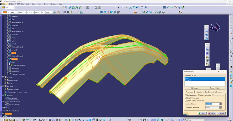
9) Join all Extended Surfaces with Offset Band Rename as Class B surface.
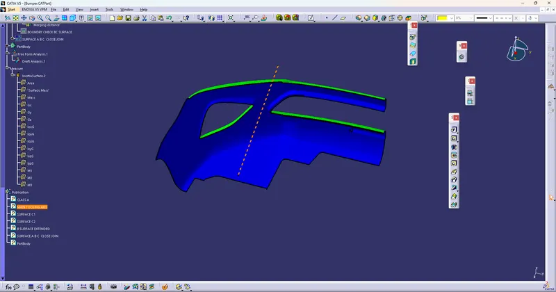
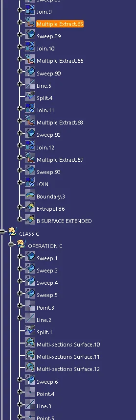
10) To create a C surface Extract Lines from Edges of Class A surface and By using With the Draft angle and With surface, reference command perform Sweep Operation. At curvature Use Multisection Surface. Ensure the Sweep should be more than the Offset distance and the Draft angle should be given during the operation.
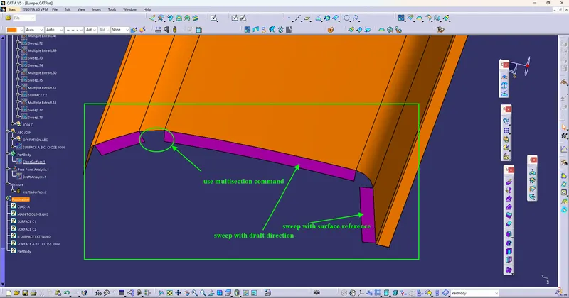
11) Join All C surfaces and Create a single Surface, At the corners, extend each face and trim them.
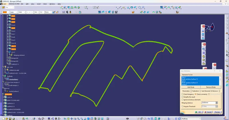
12) Trim Surface C and B and then Join Surface A B and C together.
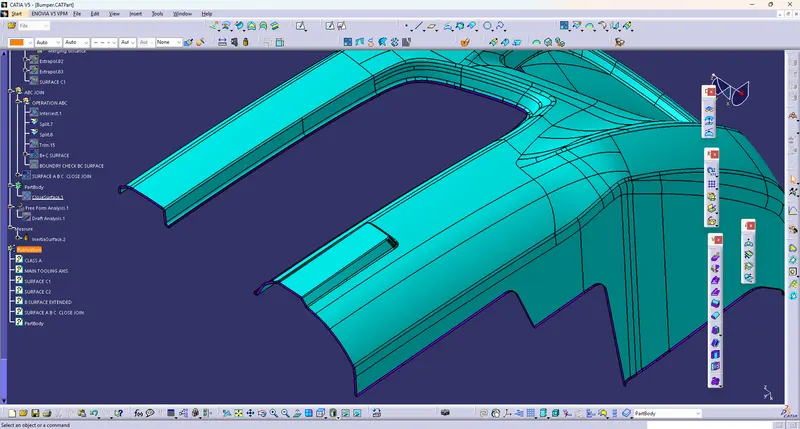
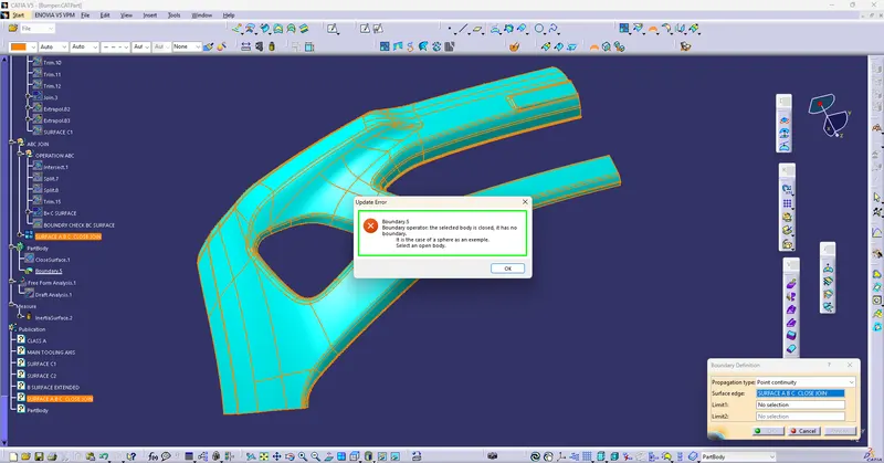
13 )Join ABC surface check by Boundry Option if Boundry is not Form it means Created All three Surface are Closed successfully.
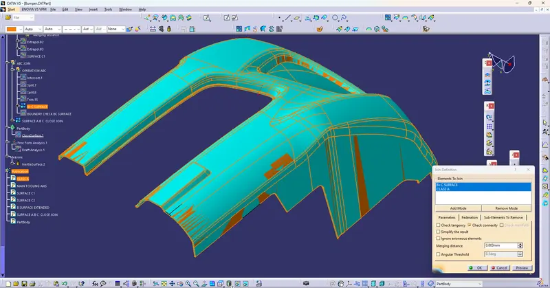
14) Go to Part body design and Create a Solid body From Joined ABC surface.
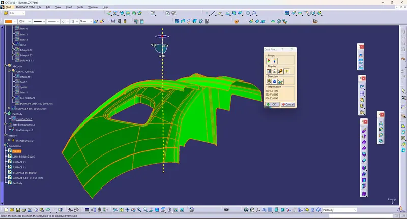
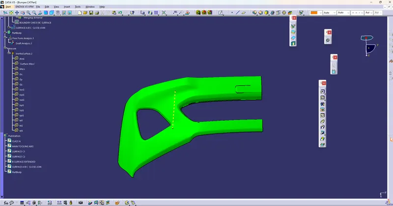
15) Perform Draft analysis on Part Body ( Solid Body), all faces Should be Green in the Result.
Observations:-
1) Class A surface check and Repaired properly.
2) Draft analysis for Class A is passed.
3) Class B surface Boundary check properly and No patches or gaps are noticed.
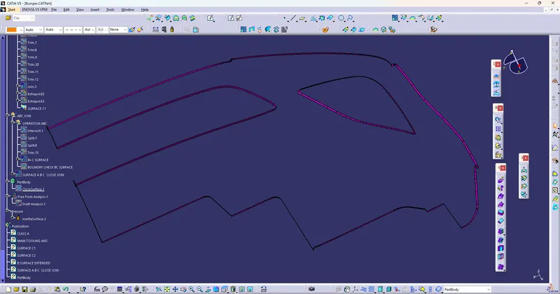
4) Class C surface Boundary check Properly and No gaps or patches are Noticed.
5) Join ABC close surface Check with boundary and Gives error No Boundry formed
6) Draft analysis for Solid Body is Passed.
CATIA Part Details
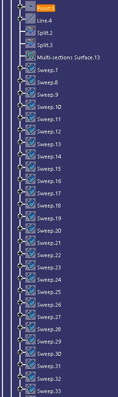
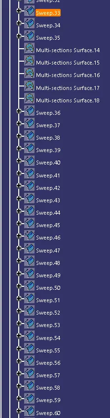
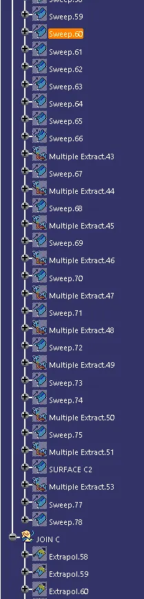
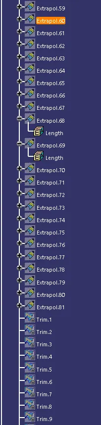
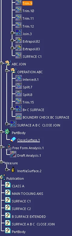
1) Feature Tree
2) FV, ISO, and SV